
Abstract
The present paper reports an experimental study on the fabrication and characterization of aluminum-oxide-reinforced functionally graded aluminum composites and optimization of drilling parameters on thrust force and average surface roughness using gray relational analysis. For this purpose, AA7075/Al2O3 functionally graded materials were produced with three layers that have different ratios of Al2O3 via high-temperature isostatic pressing and powder metallurgy method. Hardness behaviors of the layers were determined. Further, microstructural characterizations of the layers were carried out. Functionally graded materials were machined at dry cutting conditions with a 6 mm uncoated cemented carbide drill bit. The drilling experiments were carried out under different conditions such as point angles, helix angles, and feed rates, while the 25 m/min cutting speed was kept constant. The effects of factors on thrust force and surface roughness were evaluated using analysis of variance and gray relational analysis in full factorial experimental design. The minimum thrust force was measured at 221 N in a 140° point angle, 15° helix angle, and 0.075 mm/rev feed rate. Results of the gray relational analysis showed that feed rate was the dominant factor on thrust force and average surface roughness. Consequently, the highest and lowest gray relational grades were obtained at 0.899 and 0.374, respectively.
Introduction
Aluminum alloys (AAs) are preferred materials in engineering applications because of their high specific strength and stiffness as well as low density.1,2 However, the main problem is that AAs have poor endurance in high temperatures. Among all AAs, the 7xxx series demonstrates the highest room-temperature strength. The 7xxx series can be strengthened by heat treatment through contained extremely fine and uniformly dispersed precipitates.3,4 Adding a ceramic particle to AAs increases the mechanical properties at high temperature. Aluminum oxide (Al2O3), boron carbide (B4C), and silicon carbide (SiC) ceramics are commonly used reinforcements in aluminum composites.5–7 Al2O3 is one of the most important strengthening materials because of its excellent properties (e.g. high hardness, chemical stability, strength, corrosion resistant, low thermal expansion coefficient, cost, etc.).8,9
Functional graded materials (FGMs) are composites in which the material composition gradually changes in a certain direction according to the desired properties.10,11 Thanks to continuous change in their microstructures, FGMs are distinguished from conventional composites in high-temperature surface-wear resistance, increased adhesion at the ceramic–metal interface, and fracture toughness, along with reduced interfacial and thermal stress. 12 FGMs are used in many fields such as aerospace, defense, biomedical, nuclear, cutting tools, and electronics.13,14 There are many different approaches to the production of FGMs such as chemical vapor deposition, centrifugal casting, spark plasma sintering, and powder metallurgy. 15
Powder metallurgy (PM) is widely used in the production of FGMs due to its comprehensive control over the microstructure and ability to form shapes. In addition, shorter production times, simple processing equipment, low cost, and energy consumption are other advantages of PM. 16
PM, which is a technique for producing parts near net shape, has four primary steps: (1) preparation of powder considering predesigned dispersion; (2) mixing of powder; (3) forming; (4) and sintering. However, secondary machining processes (e.g. drilling, turning, milling, etc.) are required when parts geometry has small holes, tiny walls, and fine finishing tolerance. 17 Especially to reduce huge mold cost and to increase mold life, the geometrical elements (e.g. hole, screw, etc.) are formed secondary machining processes. 18 Karabulut et al. 19 studied the effect of reinforcement element type on surface roughness and chip formation to determine the drilling behavior of metal matrix composites. The authors fabricated three types of composites, which have 10 wt.% Al2O3, wt.% B4C, wt.% SiC, via the powder metallurgy and hot-extrusion method. The authors further observed that better interfacial bonding of between reinforcement and matrix was Al2O3-aluminum samples. They also determined that better holes surface quality appeared in Al2O3-aluminum samples. The authors explained the reason as ductile machining with short chip formation.
Determining the machinability properties of materials is a complex and multifactorial problem. Multiresponse optimization methods are used to determine the optimum process parameters in several machining methods. 20 Gray relational analysis (GRA) is one of the effective multiresponse optimization methods used to evaluate the effects of factors and their levels. 21 GRA creates optimized response input parameters, which have different weights of evaluation. 22 Ranking of process parameters can also be accomplished by considering the effect of all response parameters. 23 In addition, the absence of complex formulas and calculations in GRA makes this technique easier and flexible. For these reasons, many researchers have used the GRA optimization method in their studies. Haq et al. 24 investigated the effect of machining parameters (i.e. cutting speed, feed rate, point angle) of Al/SiC metal matrix composites on cutting force, torque, and surface roughness using GRA and ANOVA. From this analysis, it was reported that point angle, cutting speed, and feed rate were effective in drilling with the contributions of 43.2%, 28.64%, and 26.21%, respectively. Babu et al. 25 examined the optimum drilling parameters of SiC-reinforced aluminum functionally graded composites using GRA. They fabricated experimental samples using the centrifugal casting method. They further reported that feed rate and drilling zone (as varying reinforcement rates) are the major factors with the contribution of 56.67% and 32.95% on the drilling process, respectively. Taşkesen and Kütükde 26 optimized the effect of the drilling parameters (i.e. feed rate, spindle speed, drill type) and reinforcement ratio on thrust force, torque, and surface roughness using GRA. The authors indicated that the most effective factor in machining was the reinforcement ratio. They also reported that surface roughness decreased with increasing the reinforcement ratio for the carbide tool. Rajeswari and Amirthagadeswaran 27 investigated the effect of spindle speed, feed rate, depth of cut, and ratio of reinforcements on the milling of Al7075-based SiC-Al2O3-reinforced composites. The authors used ANOVA to obtain the most influencing parameters on thrust force and torque. According to the ANOVA, the ratio of SiC and spindle speed were dominant factors. The authors observed that increasing the feed rate increased thrust force and torque. Tosun and Muratoglu 28 investigated the effect of drill types (i.e. HSS, TiN-coated HSS, carbide) and point angles (90°, 118°, 130°) on drilled surface damage during drilling of 17 wt.% SiC-reinforced AA2124 composite material. The results of this study showed that solid carbide drills produce better surface roughness compared with TiN-coated HSS and HSS drills; further, a 130° point angle was suggested due to reduced damage zones with an increase of point angles of drill bits.
Cutting tool wear negatively affects machined surface quality, hole diameter tolerance, and geometry. Analysis of tool wear is important for better machining operation. In particle-reinforced metal-based composites, especially, aluminum alloys have a greater tendency to stick to the cutting tool under dry machining conditions. 29 During the cutting process, a built-up edge (BUE) is formed as a result of the soft workpiece material sticking to the cutting edge of the cutting tool. 30 Several factors such as type, percentage and size of reinforcement, and tool can affect tool wear when drilling metal matrix composites geometry (e.g. point angle, helix angle, etc.), and drilling parameters (e.g, feed rate, cutting speed, etc.).31–34 Choosing the right parameters is crucial for improving the process efficiency of metal matrix composites. 35
The literature includes many experimental studies on drilling properties of metal matrix composites in terms of the evaluation of surface roughness, thrust force, and tool wear. However, comprehensive studies on the drilling properties of FGMs, to our best knowledge, were not observed. Determining the drilling parameters and drill geometry of FGMs is of great importance for processing cost and material quality since the ratio of reinforcement in it varies according to the different zones.
The main aim of this research is to ascertain the mechanical and drilling performance of AA7075/Al2O3 FGMs. For this purpose, three layered AA7075/(20-40-60 wt.% Al2O3) FGMs were produced by high-temperature isostatic pressing and powder metallurgy method. Hardness properties of the layers were tested by the Vickers hardness-measurement technique, and microstructural investigations were carried out to determine metallurgical properties using SEM. Drilling experiments were done to examine the impact of the parameters (i.e. point angle, helix angle, and feed rate) on thrust force (Fz), average surface roughness (Ra), and tool wear. The experimental results were reported using ANOVA. The GRA method was used to evaluate the effects of tool geometry and feed rate on the thrust force and surface roughness parameters together.
Material and methods
Fabrication of FGMs
FGMs were fabricated using high-temperature isostatic pressing and powder metallurgy methods. AA7075 was used as a matrix material, and Al2O3 was used as a reinforcement material. The average particle sizes of AA7075 and Al2O3 were 150 and 10 µm, respectively. In sample production, first, AA7075 and Al2O3 powder materials were weighed on a weighing instrument according to their weight percentage. Then, the prepared AA7075/Al2O3 powders were mixed in a Turbula mixer for 45 min to prevent agglomeration. The mixed powders were layered in a lubricated die starting with AA7075/Al2O3 20 wt.% at the bottom and finishing AA7075/Al2O3 60 wt.% at the top. The hot-pressing die was fabricated hot work steel (AISI 2344) and hardened with a heat treatment process. The AA7075/Al2O3 powders were pressed at 10 MPa for 2 min at room temperature. After pre-pressing, the compact FGMs were heated at 450°C for 30 min. Then, the FGMs were pressed at the condition of 325 MPa and 450°C for 30 min. They were cooled at room temperature. Five samples were produced in this study. Three of them were used for mechanical and microstructural confirmation, and two were used for drilling experiments. The AA7075/Al2O3 FGMs preparation is summarized in Figure 1. FGMs were produced in 60 × 60 × 12 mm dimensions with each layer at 4 mm.
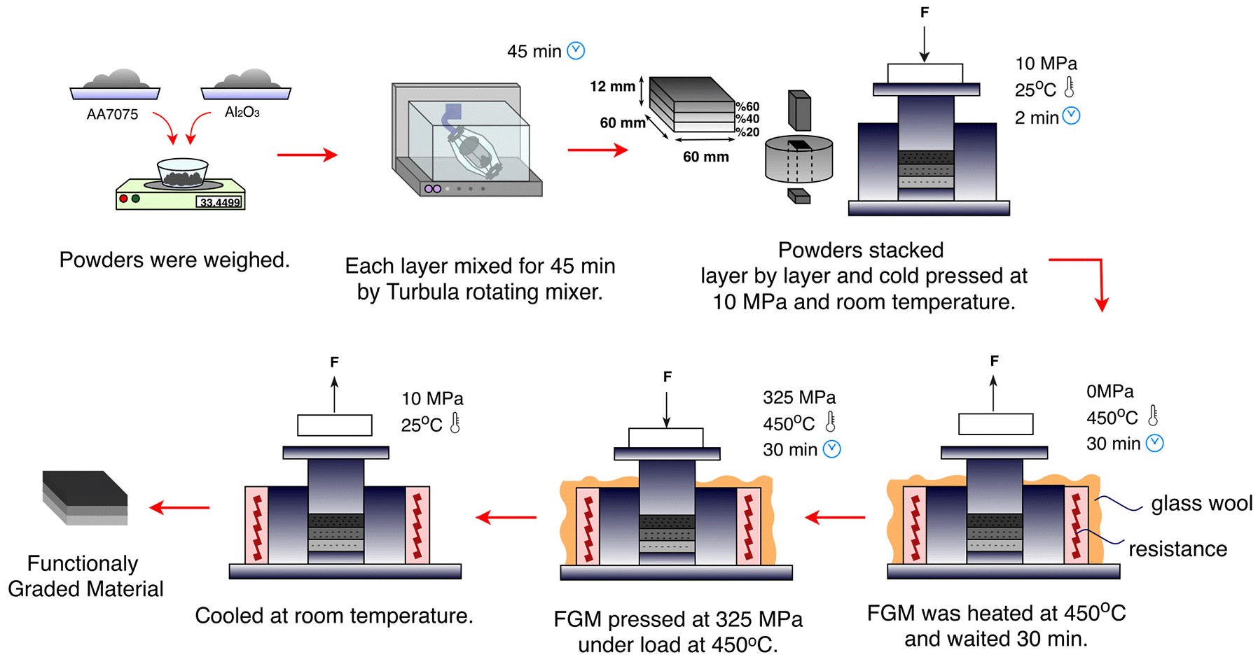
Schematic diagram of production of functionally graded materials.
Mechanical and microstructural analysis
The microstructure and distribution of Al2O3 in the metal matrix was observed using a scanning electron microscope (SEM). For this purpose, first, three test specimens were sectioned and then prepared according to standard metallographic sample preparation techniques. The microhardness of FGMs was measured with a Vickers hardness (HV) test machine under 1 kg load applied for 15 s. Microhardness measurements were performed at five different regions for each layer and repeated on three different samples. The average hardness values of the layers were calculated by taking the average of the results.
Experimental setup
Drilling trials were done by a CNC vertical machining center (Johnford VMC-550 Fanuc Series O-M). A “Kistler 9272” dynamometer with “Dynoware” software was used to measure the drilling forces (Fx, Fz, and Fz). A Schunk BT40 holder was used for the drilling. The drills were specially manufactured using cementite carbide bar material (Ceratizit; P-line, submicrometer carbide grade code: CTS12D) by KARCAN Co. cutting tools with a diameter of 6 mm to examine the impact of drilling parameters (i.e. point angle, helix angle, feed rate) on thrust force, average surface roughness, and tool wear. Drilling experiments were carried out from top layers of FGMs (60 wt.% Al2O3) to bottom layers (20 wt.% Al2O3) in dry conditions, which are shown in Figure 2. The average surface roughness of a drilled hole was measured using the Mitutoyo (SJ-410 Series) surface roughness test machine according to the ISO 1997 test standard. The surface roughness of holes was measured in the machining direction. Each hole was measured four times by rotating the hole position 90°. Tool wear of drill bits was observed using a Nikon ShuttlePix microscope. Tool wear images were taken at 25× and 225× magnification. Unit measurement lengths are given on the images.
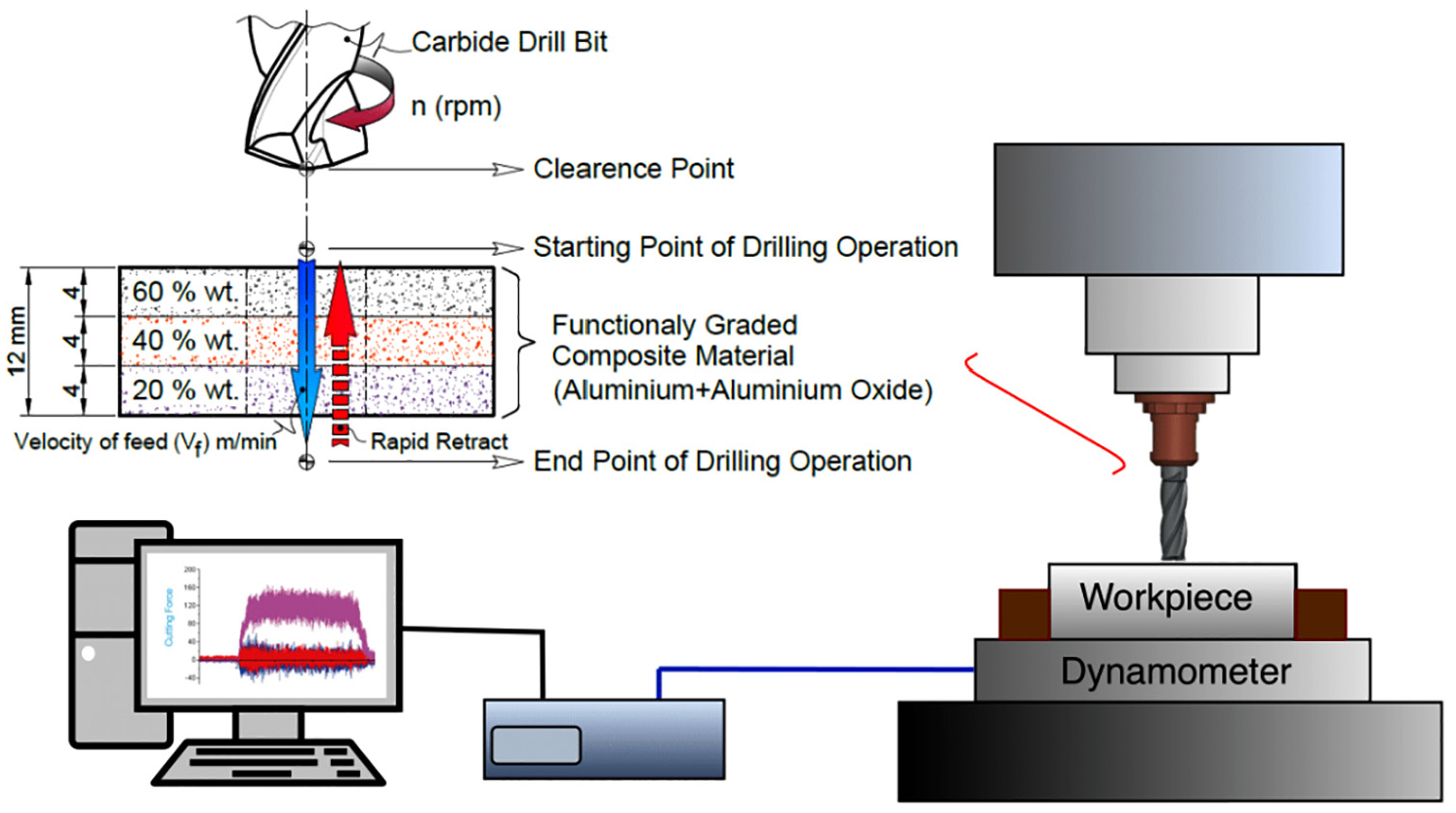
Experimental setup of the drilling process.
Experimental design for drilling
The experimental drilling tests were made by using a full factorial (FF) design. FF enables testing of all possible combinations of the levels of each factor. FF allows us to examine the influence of each factor on the response variable. Also, it is one of the effective methods used to determine the impacts of interactions between factors on the response variable. In this study, the control parameters such as point angle, helix angle, and feed rate were varied to investigate the effect of tool geometry on thrust force (Fz) and surface roughness (Ra). Three different levels were selected to determine the effect of control parameters, as shown in Table 1.
Control parameters and their levels.
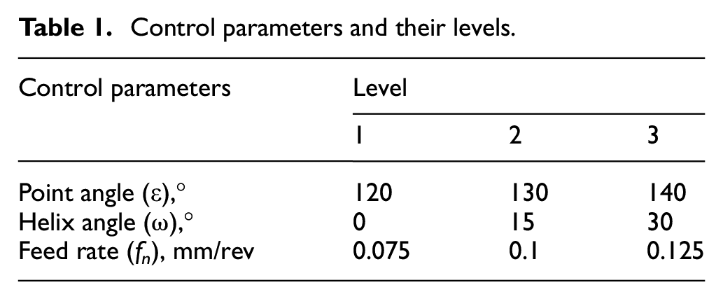
Drilling is a multifunctional complex operation. In order to clearly determine the effect of tool geometry on the drilling of functionally graded composites, tool diameter (6 mm) and cutting speed (25 m/min) were taken as constants. Drilling experiments were done in dry conditions. A total of 27 ([level number]factor number = 33) experiments were conducted within the scope of full factorial experiment design.
GRA
GRA is a multiresponse optimization technique. The GRA determines the basic relationships between the factors of a system that has less information on data and cannot be modeled due to uncertainties. 36 There is no complex formulas and calculations in the field of gray relational analysis that make this technique easy and feasible. 24 GRA is also a grading, classification, and decision-making technique.
The calculation stages of the gray relational analysis method are as follows:
The reference series of
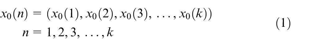
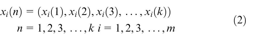
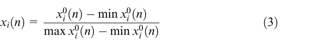
Experimental data are normalized in series to make comparisons between series, which have different measurement units. Normalization is between
The larger, the better
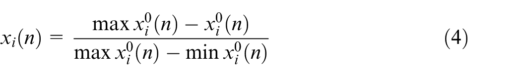
The smaller, the better
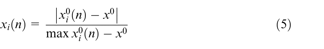
The nominal, the better
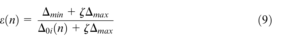
The gray relational coefficient (ε) is used to describe the relationship between ideal and normalized results.


The GRG is a measure of the geometric similarity between the series
It takes the first place with the maximum gray relational degree and ranks from the value with the higher gray relational coefficient to the lower one.
ANOVA is used to determine the factor that has a significant effect on the gray relational degree.
The total mean values are calculated based on GRG response values to the determine optimum parameter levels. The factor with the highest total mean value among the factors gives the optimum level. 39
Results and discussions
Mechanical and microstructural properties
AA7075-based FGMs reinforced with Al2O3 (20-40-60 wt.%) were produced by high-temperature isostatic pressing and powder metallurgy method. The microstructure of the powders, which are used in the production of FGMs, is presented in Figure 3.
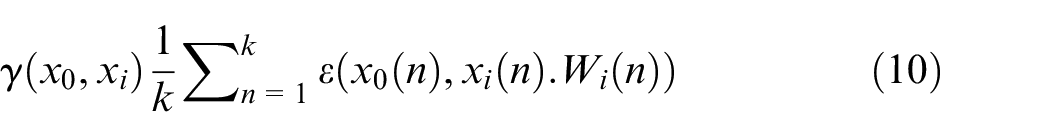
SEM image and EDX of powders used for fabrication of FGMs: (a) AA7075 and (b) Al2O3.
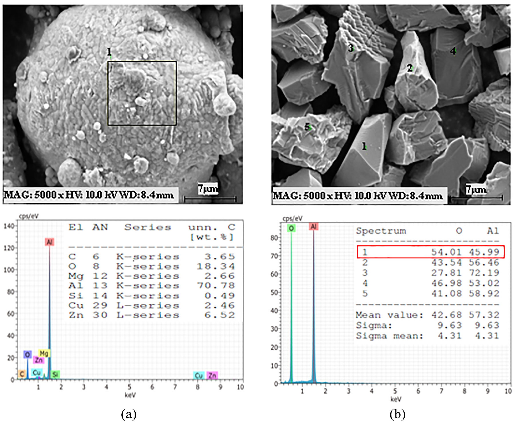
It can be seen that aluminum powders have a spherical shape, while Al2O3 ceramics powders have an angular shape. The SEM image of the microstructure of the produced FGM sample is given in Figure 4. Formation of a metallurgical bond between the layers allowed for a continuous transition from one layer to another. 40 The increase of Al2O3 caused an increase in the tendency of the ceramic particles to agglomerate. Due to the agglomeration, a smooth interface bond between the ceramic–metal matrix could not be established. Particle distribution was better in the layer containing Al2O3 20 wt.%. However, full densification in the sample was not observed. The porosity was increased with an increasing amount of reinforcement.
Microstructure of AA7075-Al2O3 FGMs: (a) between top and middle layer, (b) top layer of FGM, (c) between middle and bottom layer, (d) middle layer of FGM, and (e) bottom of FGM.
The microhardness of the FGM layers was evaluated. The influence of the amount of reinforcement ceramics on the hardness of layers is shown in Figure 5. The average microhardness of the layers containing 20 wt.% Al2O3, 40 wt.% Al2O3, and 60 wt.% Al2O3 was measured at 105.8, 126.4, and 102.8 HV, respectively. The hardness of all layers was significantly higher than AA7075 (78 HV) 26 hardness. The increasing microhardness of these layers with the Al2O3 content increasing is related to the dispersion strengthening. 41 However, it was observed that the hardness value of the layer with 40 wt.% Al2O3 constituted a turning point. The decrease in the hardness of 60 wt.% Al2O3 layer is due to the agglomeration of reinforcing particles and higher porosity. In previous studies, this reduction was attributed to the poor bonding of the matrix and reinforcement interface. 41
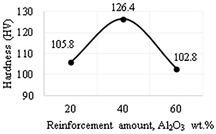
Hardness of the layers.
Thrust force optimization
Thrust force is a primary indicator of machinability on drilling materials. Usually, the high drilling forces, which occur in the machining process, cause delamination between layers and failure input and output of composite holes. Therefore, thrust force must be reduced as far as possible. Choosing suitable tool geometry (e.g. point angle, helix angle, etc.) and cutting parameters (e.g. feed rate, cutting speed, etc.) can be effective in reducing thrust force. 42
In this study, the drilling force components in Figure 6 (Fx, Fy, and Fz) were measured for all combinations of factors and their levels. Fx and Fy occur in radial directions. The radial forces in the two cutting edge balance each other. Therefore, Fz is considered as the drilling force in this study. Fz is called the thrust force applied in the Z direction. 43
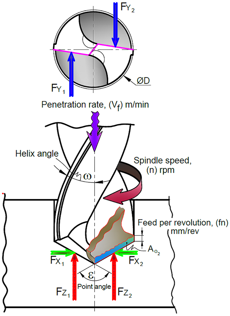
Drilling force components.
Values of the Fz measured during the machinability experiments of FGMs are presented in Table 4. Parts of the measurement data graphic are shown in Figure 7, that is, that the thrust force gradually increases during the transition from one layer to another. When changes in thrust forces were examined, it was determined that thrust forces increased ∼25% on the first interface transition and ∼27.4% on the second interface transition compared with input mean force. Three main factors are believed to contribute to this increase. First, the fact that the cutting tool is confronted with more density surface as it moves from one layer to the next, and with the increasing amount of chip volume caused increased cutting forces. Second is the effect of increased friction depending on the increased hole depth. Third is the change of tool geometry due to tool wear and BUE.
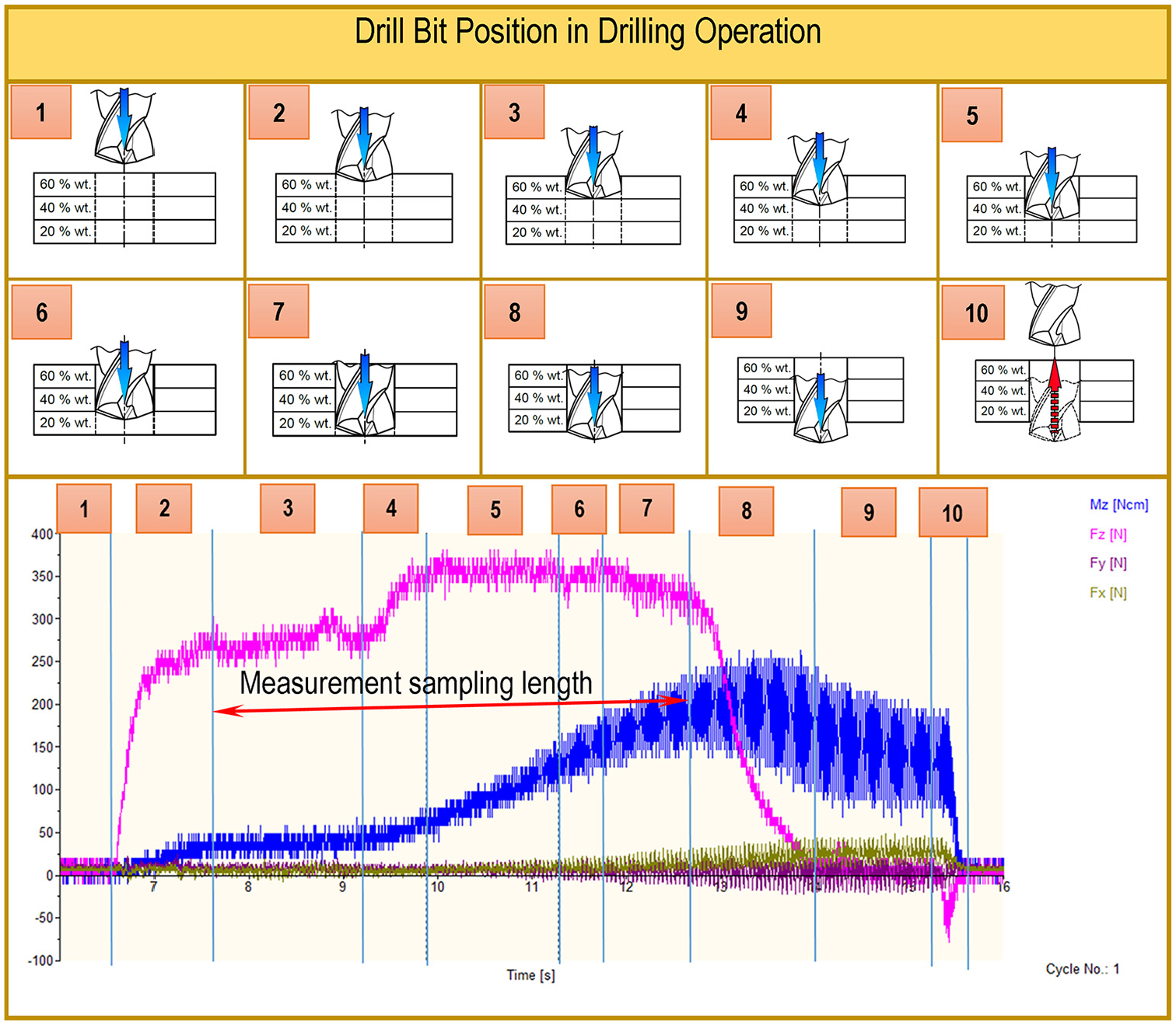
Parts of the Dynoware software data graphic by positions of the drill bit.
The mean value of the Fz was used to evaluate the results. ANOVA analysis was carried out using JMP7 software to obtain the influence of variables on the drilling characteristics. The results of ANOVA for the thrust forces are shown in Table 2. The investigation of ANOVA was used for the significance level of p = 0.05, that is, a 95% assurance level. If p is equal to 0.05 or less, it is possible to deduce that the influence of the factor is statistically significant. 44 The results of the ANOVA for thrust forces supported a strong linear relationship in the drilling models. R-square (R2) value of the analysis was 0.9177. R2 is the variance ratio of the dependent variable that can be predicted from the independent variable. 44 Based on the ANOVA results, the most influential parameter on the thrust force was feed rate with a contribution of 27.05%.
ANOVA for thrust force.
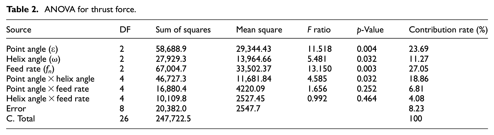
Also, point angle and helix angle were effective with contributions of 23.69% and 11.27%, respectively. Small changes in the factors with a high percent contribution will have a major impact on hole drilling. The means of Fz for each level of drilling parameters are shown in Figure 8. It is observed that an increase in feed rates increases the Fz in the drilling of FGMs, which was demonstrated in previous studies.45,46 In parallel with previous studies, it was investigated that the Fz decreases with the increase of the point angle. 25 Helix angles of 0° and 30° have a similar effect on thrust forces. The lowest thrust force was obtained at a 15° helix angle.
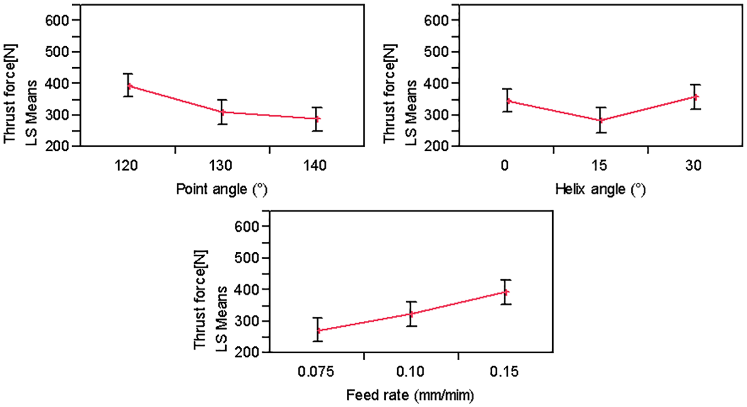
Thrust force means of factors.
Surface roughness optimizations
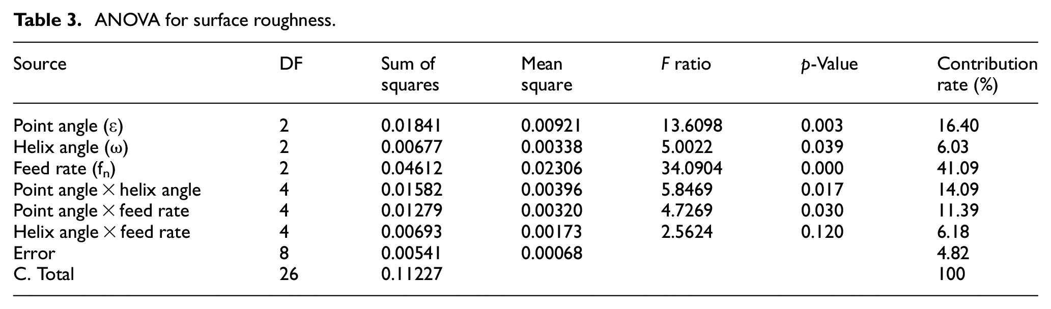
Surface roughness is an important criteria for evaluating a material’s machinability. Machined surface quality affects material properties such as abrasion, fatigue strength, creep, and corrosion resistance. 19 The results of ANOVA for the surface roughness are shown in Table 3. As a result of ANOVA, R2 was calculated as 0.9517. The analysis indicates that the feed rate was the highest influential parameter on surface roughness with a 41.09% contribution rate. Also, point angle and helix angle were effective with a contribution of 16.40% and 6.03%, respectively. The interaction of point angle with the other factors were effective on the surface roughness. However, the interactions of the helix angle and feed rate did not demonstrate a statistical effect on surface roughness.
ANOVA for surface roughness.
In parallel with the previous study, 32 it was observed that Ra increased with an increase of feed rates and decreased with a decrease of point angles, as shown in Figure 9. Maximum Ra was observed at a 15° helix angle as 0.365 µm; further, it was determined that the Ra reduced at the values below or above this value.
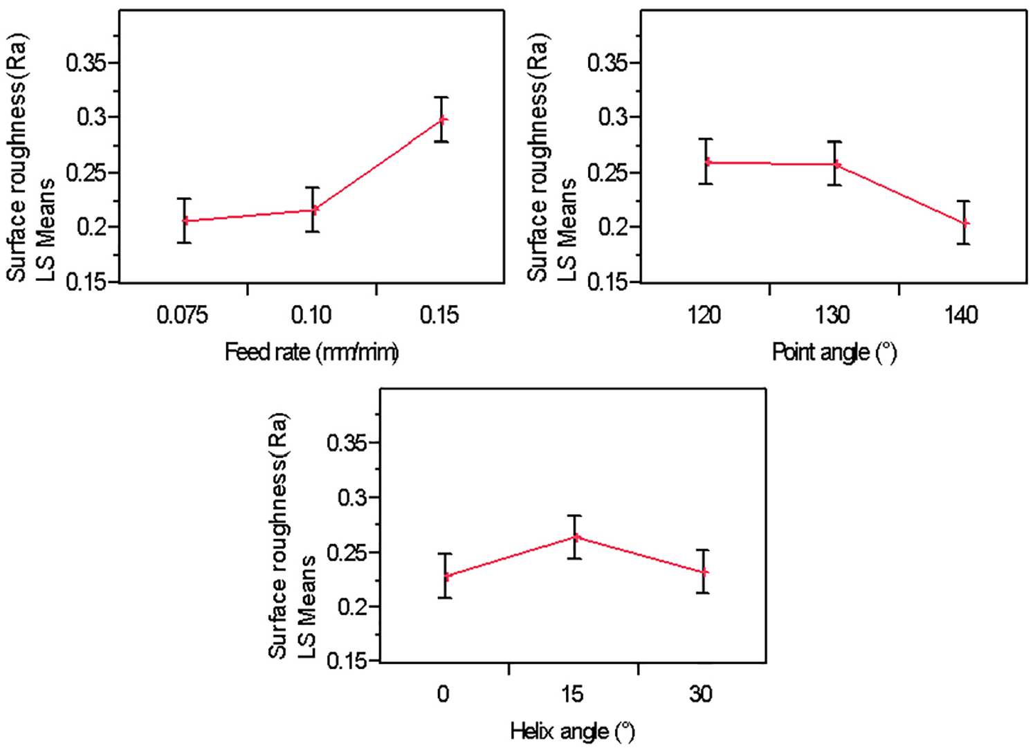
Surface roughness means of factors.
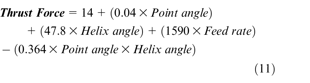
Mathematical modeling
In this study, mathematical models were created to estimate the value of thrust force and surface roughness according to control factors. The models developed can also be used to investigate the effects of significant factor parameters on the output response. Mathematical models created according to ANOVA analysis are given in equations (11) and (12). The mathematical models were verified by efficiency measures (R2) of 0.92–0.95 for thrust force and surface roughness, respectively. The comparative thrust force and surface roughness values obtained with the regression equations and experimentally are given in Figures 10 and 11, respectively. The graphs show that mathematical equations output and experimental outputs are close to each other with a trend in high harmony.
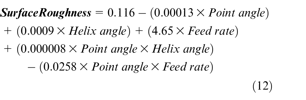
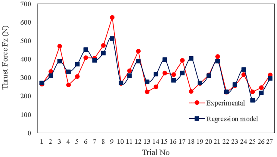
Experimental and regressional thrust force results.
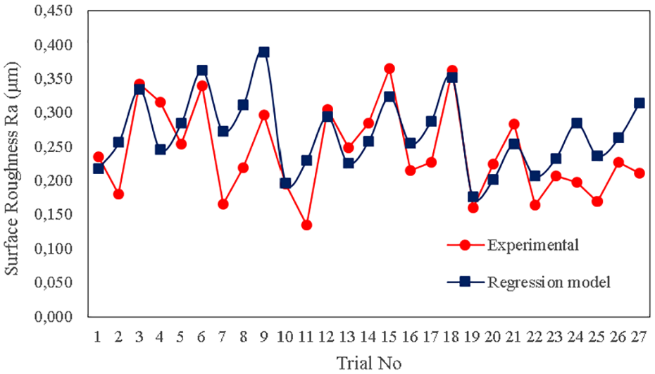
Experimental and regressional surface roughness results.
Multiresponse optimization with GRA
In this section, gray relational analysis was used to determine the optimum thrust force and surface roughness. Gray relational analysis data are given in Table 4. “The smaller-the better” method was used to normalize the result parameters (equation (4)) because the Fz and Ra values are desired lower. Deviation orders
Results of gray relational analysis.
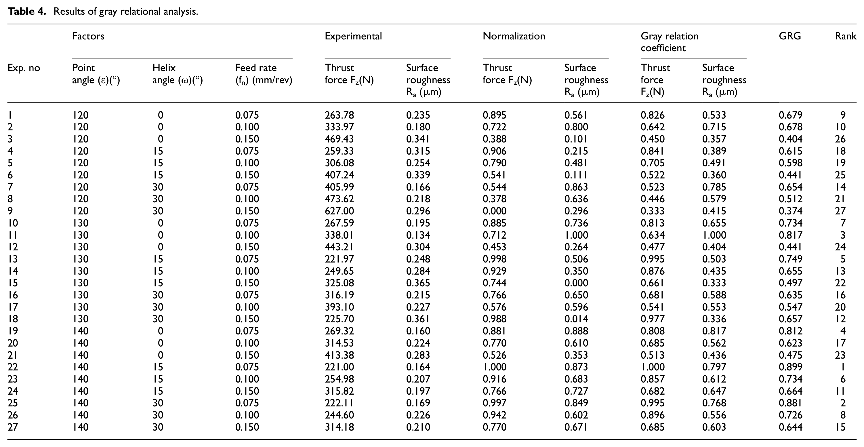
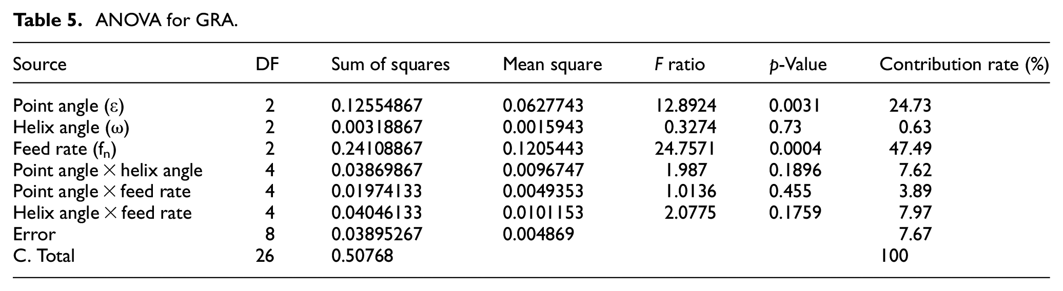
In addition, ANOVA was used to obtain the effects of factors on GRA responses. R2 was calculated as 0.9232. Table 5 shows the feed rate, point angle, and helix angle, which influenced the GRG values with percentages of 47.49%, 24.73%, and 0.63%, respectively. These results show that the feed rate was the most effective parameter on the GRA value.
ANOVA for GRA.
GRA response values were determined. The parameter levels are shown in Table 6. The value that has the maximum response value among the levels gives the optimal parameters for the experimental design. The optimum response was attained in the array of “ε3-ω2-fn1.” The values were 0.71756, 0.65022, and 0.73978, respectively. Total mean value of the GRA was calculated as 0.63500.
Response table for GRA.
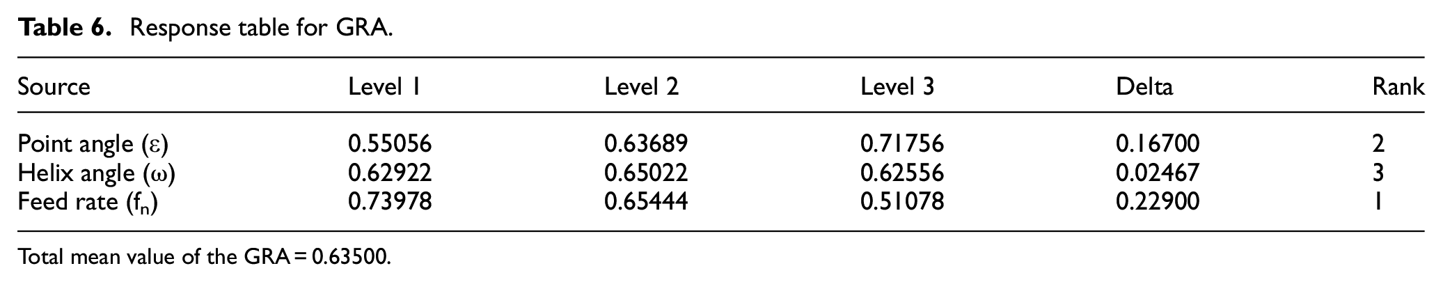
Total mean value of the GRA = 0.63500
Tool wear
Tool wear is an expected situation in machining and drilling processes. In this section, the effects of tool geometry (point angle and helix angle) on the tool wear in the drilling of AA7075/Al2O3 FGMs were evaluated. In order to understand the effects of tool geometry on tool wear, the feed rate was kept constant as fn: 0.075 mm/rev. Figure 12 shows the tool wear images formed at different point angles (120°, 130°, 140°) at a constant 30° helix angle. The high adhesion tendency of the matrix within the structure and the high hardness of the reinforcement particles caused the formation of built-up edge (BUE) on the cutting tool rake face. Similar BUE formation was detected at all point angles. BUE tended to increase in the cutting-edge cutting line toward the center of the drill bit. Also, it was observed that the aluminum matrix was deposited on the chisel edge. When the buildup on the chisel edge length was measured, the maximum value was observed as 0.785 mm at the 120° point angle. This was attributed to narrow tool geometry in previous literature studies, which caused high friction between the tool and workpiece.34,35 Figure 13 shows the tool-wear images formed at different helix angles (0°, 15°, 30°) at a constant 120° point angle. BUE and buildup on the chisel edge were observed at all helix angles. According to the measurements, it was determined that the buildup on chisel edge lengths were 0.425, 0.310, and 0.778 mm, respectively. The lowest buildup on the chisel edge was observed at a 15° helix angle. It is known that tool wear is related to cutting force. Previous studies proved that the increase in cutting force increases the machining temperature, which increases the tendency of the workpiece material to stick to the tool.34,47,48
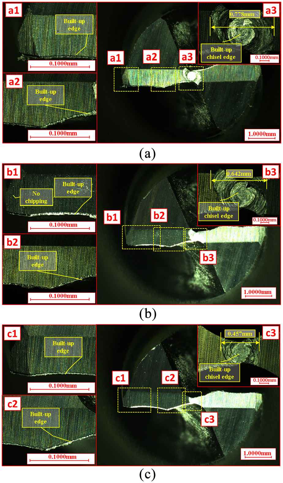
Images of tool wear according to point angle: (a) 120°, (b) 130°, and (c) 140°.
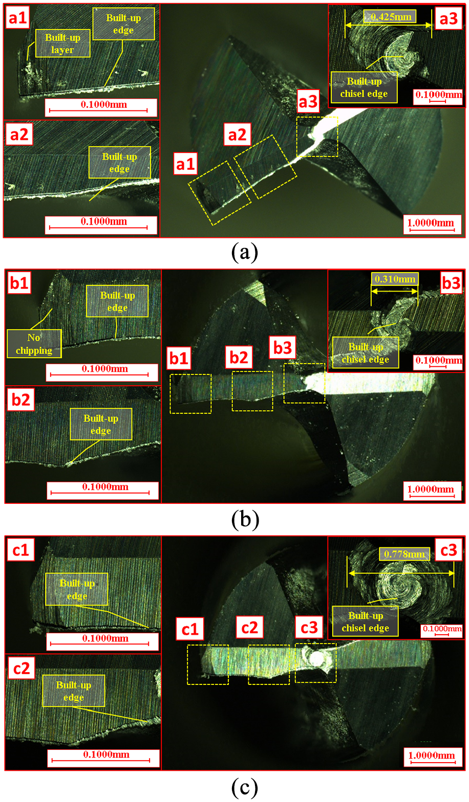
Images of tool wear according to helix angle: (a) 0°, (b) 15°, and (c) 30°.
Conclusions
In this study, the effect of tool geometry and drilling parameters on Al2O3-reinforced FGMs was investigated. To our best knowledge, there is not enough study in the literature about the drilling processes of materials with varying reinforcement ratios throughout the drill holes. The investigation of the drilling process of functionally graded materials is important for the literature. Al2O3-reinforced functionally graded aluminum composites were fabricated by powder metallurgy. The microstructure of composites was investigated by SEM images. Thrust force, surface roughness, and tool wear were taken into consideration as performance criteria. Full factorial design was used in experimental design, and the results were analyzed by using ANOVA and GRA. The results obtained in the study are summarized below.
The SEM image of the FGMs indicate that Al2O3 powders were not uniformly distributed in the layers of the composite. It was also observed that the porosity and agglomeration increase with an increasing amount of reinforcement.
The hardness was affected by the amount of Al2O3 in the layers. Maximum hardness was measured as 126.4 HV in the 40 wt.% Al2O3-reinforced layer.
Based on ANOVA, feed rate was the most effective parameter on thrust force with a contribution of 27.05%. In addition, the effects of the point angle and helix angle were 23.69% and 13.01%, respectively. Fz increased when feed rates increased. However, it decreased with an increasing of point angle. The minimum Fz was measured at 221 N in a 15° helix angle.
The ANOVA indicated that the feed rate was the most dominant factor on surface roughness with a contribution of 41.09%, followed by point angle 16.40% and helix angle 6.03%.
Regression equations developed by input parameters affecting thrust forces and surface roughness were obtained at high R2 such as 0.82 and 0.95. Accuracy of the mathematical equation has been proved by graphs comparing experimental and mathematical data.
According to the GRA, the “ε3-ω2-fn1” set has the maximum response value among the levels and gives the optimal parameters for the experimental design. The optimum results of GRA were found as Ra = 0.164 µm and Fz = 221.0. In addition, the significance of the factors on the GRG were the feed rate, point angle, and helix angle, respectively.
A built-up edge and built-up chisel edge were observed in all cutting tools. Optical images showed that the minimum built-up chisel edge length (0.310 mm) occurred at the 15° helix angle.
Determining the appropriate tool geometry and drilling parameters in the machining of FGMs prevents material waste and reduces production costs. Therefore, determining the drilling behavior of FGMs has great importance in terms of cost, time, and final product quality. This study fills a wide gap in the determination of the appropriate tool geometry and drilling parameter for drilling FGMs with an uncoated carbide drill in dry conditions. The effect of tool coating and cutting fluids on drilling behavior can be tested for further investigation.
Footnotes
Acknowledgements
Thanks to the OYP program for the financial support and KARCAN Co. for support in the research.
Declaration of conflicting interests
The author(s) declared no potential conflicts of interest with respect to the research, authorship, and/or publication of this article.
Funding
The author(s) received no financial support for the research, authorship, and/or publication of this article.