
Abstract
Total hip arthroplasty (THA) is one of the most well-known orthopedic surgeries in the world which involves the substitution of the natural hip joint by prostheses. In this process, the surface roughness of the femoral head plays a pivotal role in the performance of hip joint implants. In this regard, the nano-finishing of the femoral head of the hip joint implants to achieve a uniform surface roughness with the lowest standard deviation is a major challenge in the conventional and advanced finishing processes. In the present study, the inverse replica fixture technique was used for automatic finishing in the abrasive flow finishing (AFF) process. For this aim, an experimental setup of the AFF process was designed and fabricated. After the tests, experimental data were modeled and optimized to achieve the minimum surface roughness in the ASTM F138 (SS 316L) femoral head of the hip joint through the use of response surface methodology (RSM). The results confirmed uniform surface roughness up to the range of 0.0203 µm with a minimum standard deviation of 0.00224 for the femoral head. Moreover, the spherical shape deviation of the femoral head was achieved in the range of 7 µm. The RSM results showed a 99.71% improvement in the femoral head surface roughness (0.0007) µm under the optimized condition involving the extrusion pressure of 9.10 MPa, the number of finishing cycles of 95, and SiC abrasive mesh number of 1000.
Keywords
Introduction
As one of the globally-accepted orthopedic surgeries, total hip arthroplasty (THA) involves the replacement of the injured natural hip joints by prostheses. Recent demography findings 1 show the rapid aging of the world’s population which will result in the increasing demand for THA. As an example, by 2030, there will be a 174% increase in the demand for THA in the United States. 2 Therefore, the development of advanced hip joint implants, especially the automatic nano-finishing of their femoral head, is of crucial significance. The cross-sectional view of THA with the components of a hip joint prosthesis is depicted in Figure 1.
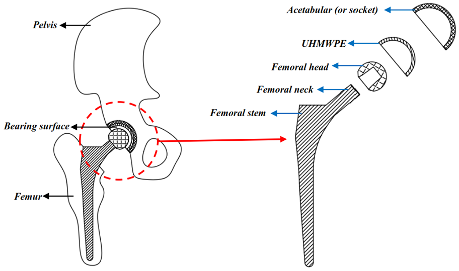
Total hip arthroplasty (THA).
As shown in Figure 1, the hip joint implant functions similarly to a mechanical bearing in which the femoral head and the femoral stem are located inside an acetabular (or Socket). An ultra-high molecular weight polyethylene (UHMWPE) is used between a femoral head and acetabular to form a bearing surface. According to the available reports,3–6 the low surface roughness of the femoral head will decline in the wear rate of UHMWPE besides a significant decrease in the bacterial adhesion of the bearing surfaces. Moreover, dimensional and shape accuracies of the femoral head are among the prominent aspects in the manufacturing of the hip joint implants. The conventional (such as grinding, and lapping) and advanced (such as magnetic abrasive finishing (MAF) and magnetorheological finishing (MRF))) finishing processes cannot be used to satisfy these requirements due to their serious limitations in terms of surface integrity, geometry, material, and productivity.7–11 Therefore, the components of the hip joint implant, especially the femoral head, are still polished manually. Despite the remarkable surface finish obtained by manual polishing, this method suffers from several drawbacks such as surface integrity, uniform surface roughness, dimensional accuracy, shape accuracy, and productivity. In this context, numerous studies have been devoted to developing, designing, and implementing novel finishing processes for the femoral head of hip joint implants, some of which will be mentioned in the following.
In Dixon et al. 12 finished and shaped the femoral head of hip joint implants made of ASTM F799 (Co-Cr-Mo alloy) using electric discharge machining (EDM) and claimed the enhanced sphericity of the femoral head. However, the use of the EDM process resulted in a heat-affected zone at a depth of 3–5 µm on the surface of the femoral head, requiring extra grinding and polishing processes to remove this layer. In another attempt, Warisawa et al. 13 used abrasive water jet machining (AWJM) for finishing the femoral head of hip joint implants with a diameter of 22.2 mm made of Co-Cr-Mo alloy. They reported the eliminated signs of grinding on the femoral surface along with achieving the best surface roughness of 0.0072 µm through the use of AWJM technology. However, the deteriorated roundness of the femoral head was declared as the drawback of AWJM technology.
In another study conducted in 2014, Zeng et al. 14 examined the finishing of the femoral head made of cobalt chrome (Co-Cr) alloy using bonnet polishing technology. They reported a 0.0161 µm reduction in the surface roughness of the femoral head. They also found a decrement in surface topographic parameters such as peak-to-valley (PV) and root mean square (RMS) from 103 to 1.36 µm and from 29.65 to 0.318 µm, respectively. Nevertheless, despite the several beneficial features of bonnet polishing technology,15,16 its lower productivity was considered as the major shortcoming. Further, the main challenge of this technology was the destruction of its finishing tools, which necessitates continuous monitoring and modification. In another attempt in 2016, Subramanian et al. 17 studied the finishing of the femoral head of hip joint implants made of Co-Cr alloy using the AFF process. They reported a surface roughness of 0.039 µm for the femoral head. Despite the significant advantages of the AFF process,18–25 the non-uniform surface finish was seen in the microscopic images; indicating that the fixture was not designed according to the geometry of the femoral head.
In the latest research in this field in 2020, Nguyen 26 introduced a method called shear thickening fluid polishing (STFP) for polishing of half-spherical surfaces made of hardened steel SKD11 with a diameter of 40 mm. Al2O3 abrasive slurry with 4000 mesh number was utilized for polishing. According to their results, the best surface roughness was 0.012 µm achieved during 15 min of finishing with the surface roughness deviation of ∼0.014 µm. The STFP method was claimed to be a convenient and efficient method for the polishing of complex surfaces. However, the results of this study revealed different surface roughness values in various regions of the half-spherical surface.
In a recent study, Döbberthin et al. 27 addressed the surface roughness and shape accuracy of the femoral head in Co-Cr alloy implants using electrochemical (EC) polishing. To achieve the lowest surface roughness of the femoral head, they implemented turning processes (for spherical-shaped machining of the femoral head), barrel finishing (for reduction of kinematic surface roughness), drag grinding (for the elimination of grinding marks), and EC polishing (for achieving excellent surface quality and high shape accuracy). The lowest surface roughness for the femoral head was 0.02 µm, which was achieved by EC polishing. They also claimed the most ideal shape deviation of the femoral head (7.5 µm) can be achieved by EC polishing. However, most of the finishing works were carried out during the barrel finishing and drag grinding processes, which took 230 min, giving rise to a 12% reduction in the surface roughness (Ra) during the EC polishing after drag grinding for 3 min. As the automatical finishing of the femoral head is not possible through a one-step process, it can be said that EC polishing has a productivity drawback.
The majority of the works in the field of AFF technology have been focused on the development of polishing media parameters due to their significant impacts on process performance.28–36 Generally, the polishing media is a combination of a viscoelastic carrier (silicon polymer, styrene polymer, and natural polymer), abrasives (silicon carbide (SiC), aluminum oxide (Al2O3), and cubic boron carbide (CBN)), and processing oil (hydrocarbon oil, naphthenic oil). On the other hand, to obtain an appropriate polishing media, the choice of ingredients must be based on four essential factors: mechanical stability, chemical stability, low cost, and environmental aspects. For instance, despite the promising results reported for viscoelastic carriers made of polyborosiloxane (PBS), its high cost has limited its application. Recently, styrene butadiene rubber (SBR) has been widely used instead of PBS due to its lower cost.37,38 In addition to cost merits, there are serious concerns about the effect of the viscoelastic carrier on human health and environmental aspects. Therefore, a novel polishing tool called an environment-friendly slurry has been recently developed to achieve high-performance surfaces while considering both economical and environmental aspects.39–47
Based on the literature review, it can be concluded that the automatic nano-finishing of the femoral head of hip joint implants to achieve a uniform surface roughness with the least standard deviation has remained a concern in both industrial and research communities. In the present work, a novel technique is designed and fabricated based on the inverse replica fixture of the femoral head in the AFF process to achieve an approximately uniform surface roughness. In this regard, an experimental setup of the AFF process was designed and manufactured. The experiments were performed based on the full factorial method to optimize and model the parameters of the AFF process such as extrusion pressure, the number of finishing cycles, and SiC abrasive mesh number to achieve the lowest surface roughness of the femoral head hip joint implants.
Materials and methods
Experimental setup of AFF process
The AFF setup along with the inverse replica fixture technique are depicted in Figure 2. The experimental setup included the AFF machine, hydraulic power unit, operation panel, two hydraulic cylinders, two medium cylinders, two micro-switches, two retaining plates, and the mechanism of upper-medium cylinder mounting arm which were connected by the mechanical fasteners. Moreover, the inverse replica fixture, inside which the femoral head is located, is tightly fastened between upper and lower medium cylinders by bolts. As shown, the upper hydraulic system and upper-medium cylinder are mounted on a movable arm using the upper-medium cylinder fixture and several M 40 bolts. This arm has vertical linear and rotational motions. Using a movable arm mechanism, the distance between the upper-medium cylinder and the surface of the inverse replica fixture becomes adjustable. Hence, it can be said that the AFF machine is designed to be automated with no limitation in the geometry and size of the parts to be polished.
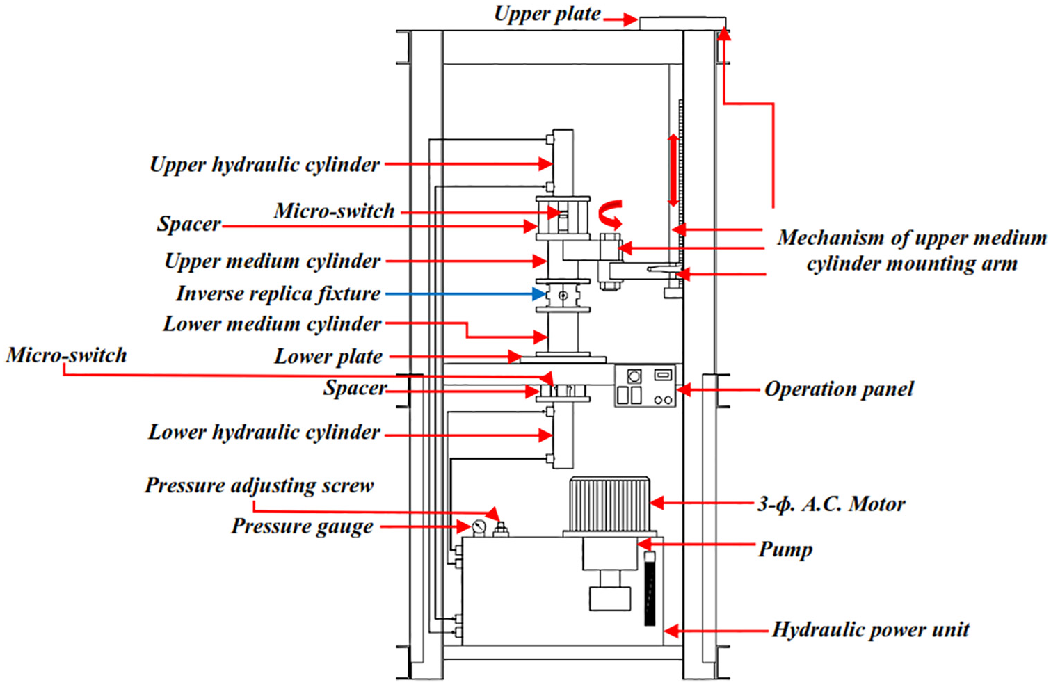
Schematic view of the AFF process setup.
Novel technique for the inverse replica fixture of the femoral head
The inverse replica fixture technique of the femoral head is represented in Figure 3. The femoral head fixture was designed and built for keeping the femoral head in the inverse replica fixture; the assembly and disassembly model of this fixture is displayed in Figure 3(a) and (b).
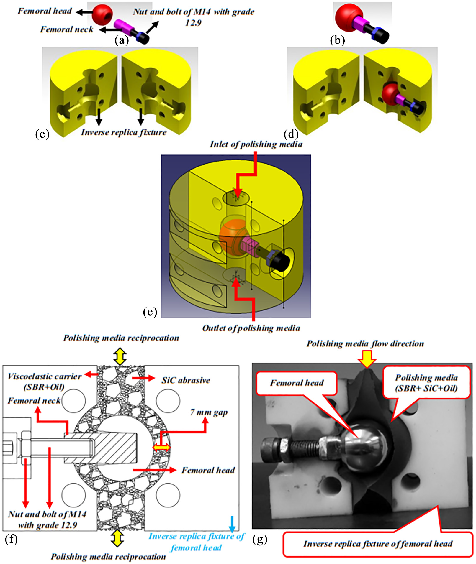
Inverse replica fixture technique of the femoral head: (a) disassembly model, (b) assembly model, (c) disassembly model for inverse replica fixture, (d) disassembly model of femoral head fixture, (e) assembly model of the femoral head fixture in reverse replica fixture, (f) schematic view of the polishing area, and (g) photograph of inverse replica fixture.
After the preliminary tests, the femoral head fixture was designed and fabricated using the femoral neck and M14 bolts (grade 12.9). In Figure 3(c) to (e), the disassembly models of femoral head inverse replica fixture, a femoral head fixture in the inverse replica fixture, and the assembly model of the femoral head fixture in the inverse replica fixture are shown in a semi-transparent state. It is worth mentioning that anti-wear polyamide was used in the fabrication of the inverse replica fixture of the femoral head regarding its unique properties in terms of strength, wear resistance, machinability, and sealability. After some preliminary tests, the optimal gap between the femoral head and the inverse replica fixture was 7 mm. The schematic and actual views of the polishing area by inverse replica fixture technique in the AFF process are depicted in Figure 3(f) and (g), respectively.
Materials
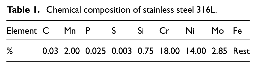
In this study, the femoral head of the hip joint implants (diameter: 28 mm and hardness: 321 BHN) were used whose chemical composition is listed in Table 1. All samples were provided by the Doostan-e-Nik Medical Services Company.
Chemical composition of stainless steel 316L.
In this research, the viscoelastic carrier of styrene butadiene rubber (SBR), SiC abrasive particles, and naphthenic oil were utilized to prepare the polishing media.
Polishing media preparation
In the AFF process, the proper combination of the viscoelastic carrier with abrasive particles and other additives determines the performance of the polishing media. To achieve the lowest roughness of the femoral head surface, after performing preliminary tests, styrene butadiene rubber (SBR) viscoelastic carrier (14 wt.%), SiC abrasive particles (78 wt.%), and naphthenic oil (8 wt.%) were applied for the fabrication of the polishing media.37,38 A two-roll mill Polymix L200 model manufactured in Germany was utilized to achieve a homogeneous polishing media. The procedure of polishing media fabrication is depicted in Figure 4. First, the viscoelastic carrier (SBR) was rolled at a temperature of 25°C–50°C. Then, SiC abrasive particles were added to the SBR viscoelastic carrier and the rolling was continued. Finally, naphthenic oil was slowly added during rolling. The polishing media exhibited high viscosity in the initial experiments so that it could not be deformed by fingers’ pressure. To reduce the viscosity and enhance the formability of the polishing media, 1%, 2%, and 3% of naphthenic oil were added according to the SiC abrasive mesh number of 240, 600, and 1000, respectively. The viscosity of the mentioned polishing media was measured using Anton Paar MCR 302 rheometer. According to the results, at a temperature of 27°C and frequency of 20 Hz, the complex viscosities have been reported as 2.1 × 10⁴, 2.3 × 10⁴, 2.5 × 10⁴ Pa · s for 240, 600, and 1000 SiC abrasive mesh numbers, respectively.
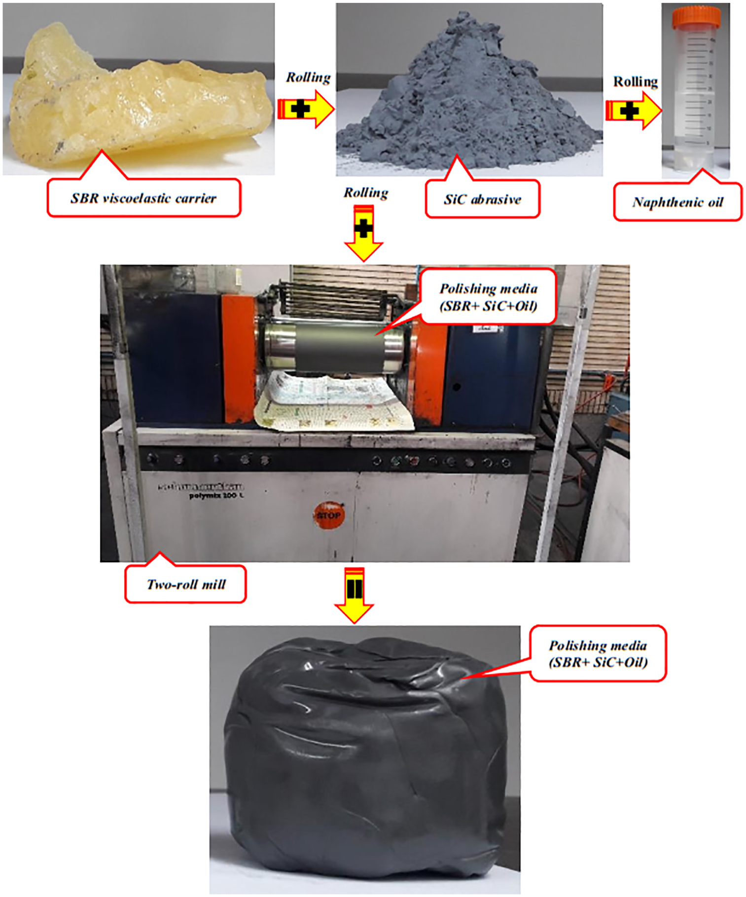
Different materials and preparation methods of polishing media.
Design of experiments
In this study, all the specimens were first cleaned with acetone before the experimental tests. In the AFF process, the surface roughness measurement (before and after the process) was carried out perpendicular to the polishing direction. The roughness measurement was carried out according to the international standard (ISO 7206-2, 1996). 48 Furthermore, the surface roughness was measured at different points on the top of the femoral head. Then, the initial roughness of the samples was recorded in different points using the Carl Zeiss SURFCOM 130A (according to ISO’97) with a cutoff length of 0.08 mm, evaluation length of 4 mm, and measurement speed of 0.6 mm/s. The average roughness was 0.245 µm. The Coordinate Measurement Machine (CMM) manufactured by Mitutoyo of Japan was used to evaluate the sphericity of the samples.
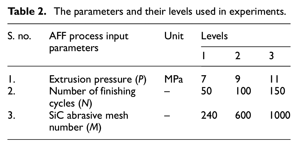
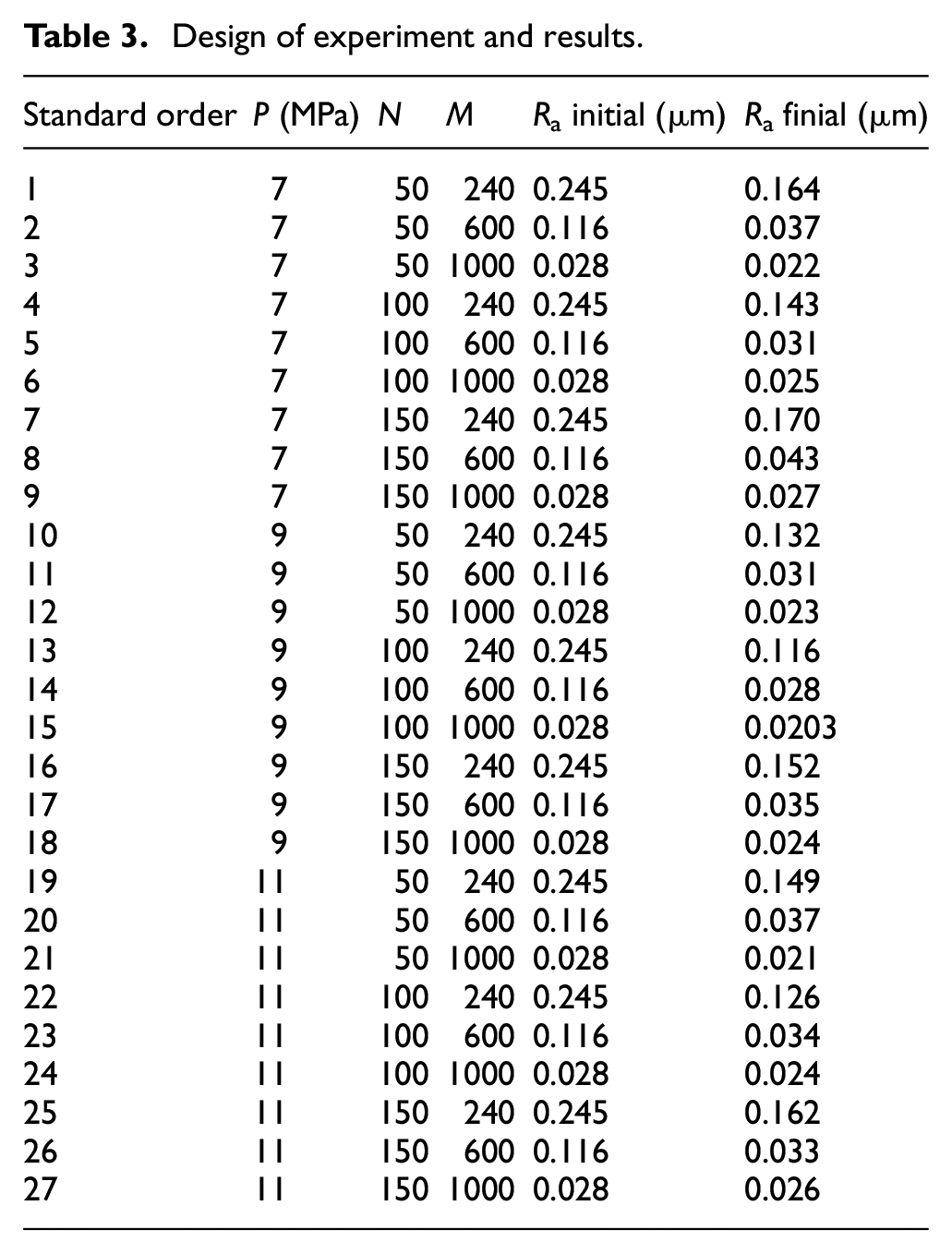
A full factorial method was employed to perform the experiments. The effect of input parameters of the AFF process (e.g. extrusion pressure, number of finishing cycles, and SiC abrasive mesh number) on the surface roughness of the femoral head was evaluated at three levels. Therefore, 27 experiments were performed in three stages of roughing (i.e. coarse abrasive), finishing (i.e. medium abrasive), and nano-finishing (i.e. fine abrasive). The parameters and their levels are listed in Table 2. After performing the tests, the specimens were cleaned with acetone and their surface roughness (Ra) was measured at several different points whose average values were recorded as final surface roughnesses. Table 3 presents the experimental data.
The parameters and their levels used in experiments.
Design of experiment and results.
Response surface methodology (RSM)
The finishing efficiency of the AFF process is dependent on the optimal amount of extrusion pressure, the number of finishing cycles, and the SiC abrasive mesh number. To achieve the lowest surface roughness and determine optimal process parameters, response surface methodology (RSM) was utilized. RSM is a well-known statistical technique for developing, improving, and optimizing the processes which has found extensive applications in various sciences.49,50 In the case of a curved response surface, a second-order model can be used to fit the independent variables and the response function. The second-order model is a practical model with the highest consistency with the experimental designs. Therefore, in the present study, the second-order model was used with the following general formulation 51 :
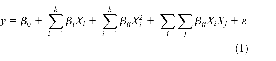
In this equation, y represents the response function estimation (surface roughness), Xi and Xj are the independent variables, k shows the number of independent variables,
Results and discussion
The effect of process parameters on the surface roughness
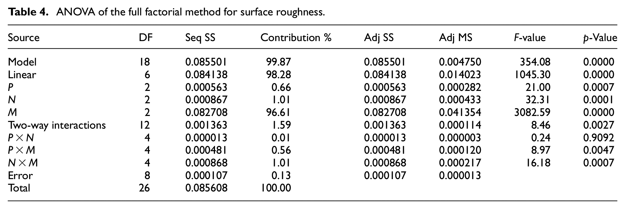
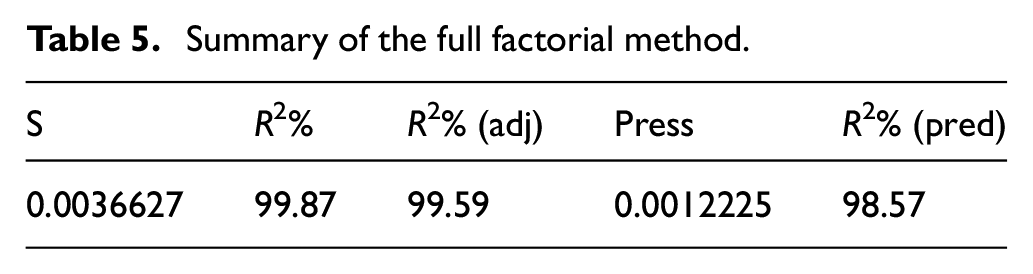
The results of the analysis of variance (ANOVA) for the surface roughness are summarized in Tables 4 and 5. According to these tables, the F-value, p-value, R2, and R2 (adj) are 354.08, 0.0000, 99.78%, and 99.59%, respectively, confirming the significance of the model. Based on Table 4, the p-values of extrusion pressure, number of finishing cycles, and the SiC abrasive mesh number are less than the confidence level of 0.05, indicating their significant effects on the surface roughness of the femoral head as shown in Figures 5, 7, and 8.
ANOVA of the full factorial method for surface roughness.
Summary of the full factorial method.
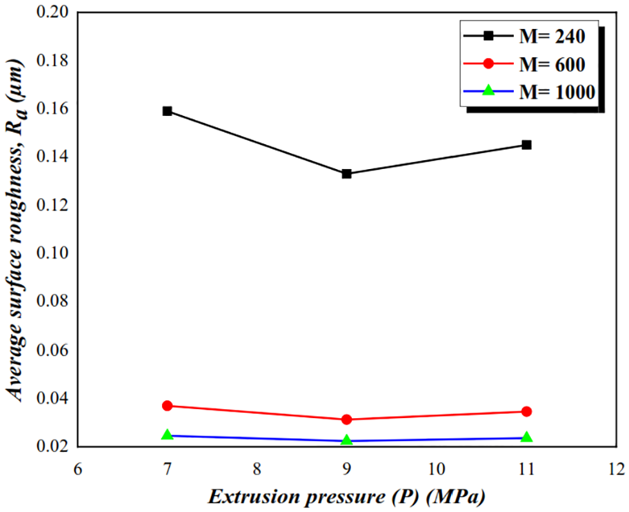
Effect of extrusion pressure on surface roughness.
In the AFF process, the penetration depth of the abrasive grains into the workpiece surface depends on the extrusion pressure, grain size, and workpiece hardness. 52 Moreover, depending on their penetration depth, abrasive particles usually leave some marks on the surface texture of the workpiece. 7 In addition to the aforementioned parameters, the correct choice of abrasive mesh number depends on the initial surface roughness of the workpiece.
The effect of extrusion pressure (P) and SiC abrasive mesh number (M) on the surface roughness of the femoral head is depicted in Figure 5. According to this figure, with the increase of extrusion pressure, the surface roughness was decreased.
The maximum reduction of surface roughness was observed in the abrasive mesh number of 240; while the best surface roughness was attained using the abrasive mesh number of 1000. By incrementing the extrusion pressure, the penetration depth of the abrasive grain and the number of active abrasive grains on the femoral head were increased, resulting in a reduction in the surface roughness. According to the results, the optimum value of extrusion pressure was 9 MPa. Further increase of extrusion pressure increased the surface roughness in such a way that the surface roughness reached its maximum at an extrusion pressure of 11 MPa. This behavior is related to the greater penetration depth of the abrasive particles on the femoral head surface. Moreover, incrementing the extrusion pressure beyond the optimal value (9 MPa) led to the formation of grain fracture within the surface of the femoral head which can be associated with the formation of new abrasive grain with smaller dimensions and sharper edges. This phenomenon was more dominant in the abrasive mesh number of 240. However, as shown in Figure 6, the effects of these factors were accompanied by the formation of cavities and micro-scratches on the surface of the femoral head, hence, deteriorating the quality of the femoral head surface.
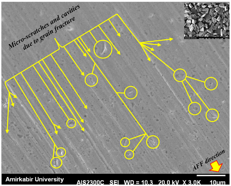
SEM image of grain fracture, cavities, and micro-scratches formed on the femoral head surface under extrusion pressure of 11 MPa, number of finishing cycles of 150, and SiC abrasive mesh number of 240.
Considering the above justifications, the following mechanisms can describe the observed behavior (Figure 5):
A. When using SiC abrasive mesh number of 240 (i.e. roughing operation), the penetration depth reached its maximum value. Thus, the variation in the average surface roughness will be maximized due to the roughing operation. In this case, coarse abrasive particles not only remove CNC marks produced by the previous turning process but also create finishing marks on the femoral head.
B. When using SiC abrasive mesh number of 600 (i.e. finishing operation), the penetration depth is much lower than that of the roughing operation. Hence, the variation in the average surface roughness will be also lower than that of the roughing operation. In this case, fine abrasive particles completely remove the marks produced by the previous finishing operations while forming new finer finishing marks on the femoral head.
C. When using SiC abrasive mesh number of 1000 (i.e. nano-finishing operation), the penetration depth reached its minimum value, minimizing the variation in average surface roughness. As a result, extra-fine abrasive particles completely remove the marks produced by previous finishing operations while generating a super-finished mirror-like surface on the femoral head.
In the AFF process, the surface quality depends on the number of finishing cycles, so that the highest surface roughness improvement occurs in the initial cycles.53,54 The effect of the number of finishing cycles (N) and extrusion pressure (P) on the surface roughness of the femoral head is depicted in Figure 7. In general, a decreasing trend can be seen in the surface roughness by increasing the number of finishing cycles. This behavior is evident in Figure 6 (for 9, 7, and 11 MPa). As can be seen, most of the finishing works were carried out in the first 50 cycles due to the initial surface roughness of the femoral head, and the best surface roughness was obtained after 100 finishing cycles. Further increase in the finishing cycles incremented the surface roughness as the surface roughness reached its maximum value after 150 cycles of finishing. The polishing media has a high viscosity in the initial cycles. Hence, the SBR viscoelastic carrier holds the abrasive SiC particles as a stiff bond. In such cases, a micro-chipping phenomenon occurs due to the initial surface roughness of the femoral head (highest surface unevenness), which is further accompanied by a reduction in surface roughness. By enhancing the number of finishing cycles, the surface unevenness was minimized. Thus, the friction phenomenon became dominant, resulting in a consequent rapid increase in the temperature of the polishing media. This will decline the viscosity of the polishing media. Subsequently, the rubbing/ sliding phenomenon occurs, loosening the abrasive grain in the SBR viscoelastic band, giving rise to rolling on the femoral head surface rather than cutting. This will decrement the quality of the femoral head surface.
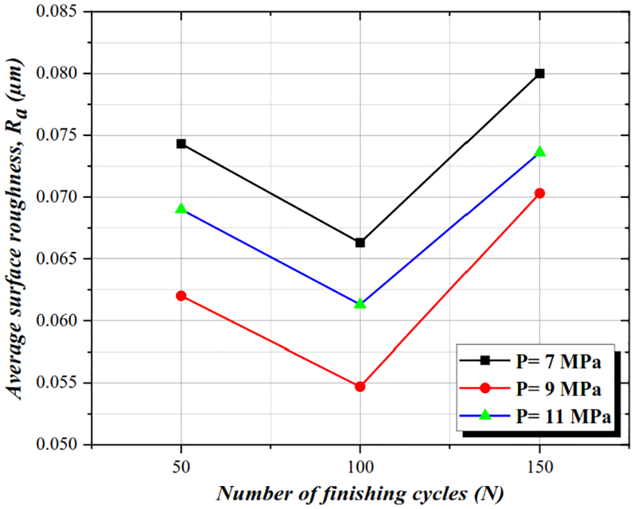
Effect of the number of finishing cycles on surface roughness.
In addition to the above discussions, the effect of extrusion pressure on the performance of the AFF process has been documented. As shown in Figure 9, first the surface roughness decreased with increasing the extrusion pressure followed by an increasing trend.18,23–34 As illustrated in Figure 9, by increasing the extrusion pressure from 7 to 9 MPa, the average surface roughness of the formal head decreased. Further enhancement in the extrusion pressure from 9 to 11 MPa, However, increased surface roughness which can be assigned to the elevation of the penetration depth, giving rise to a drastic in the surface roughness of the femoral head as shown in Figure 7. As a result of the deterioration of the surface finish of the femoral head, the average surface roughness will be increased.
The interaction between the SiC abrasive mesh number (M) and the number of finishing cycles (N) on the surface roughness of the femoral head is presented in Figure 8.
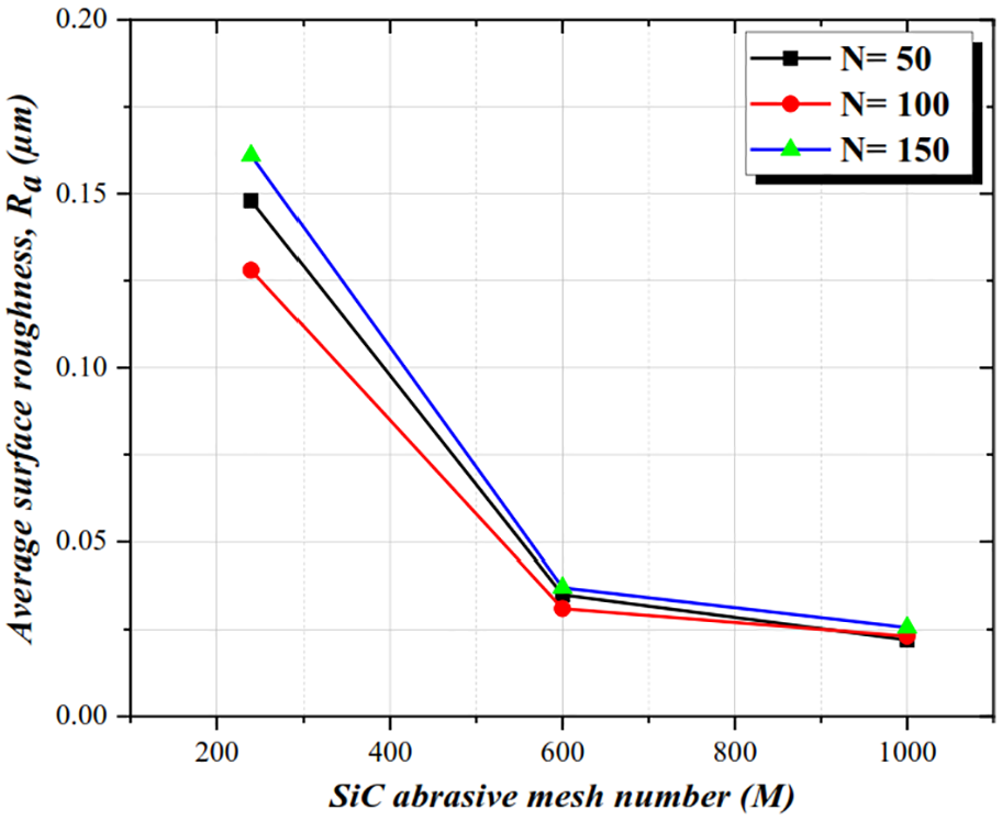
Effect of SiC abrasive mesh number on surface roughness.
Figure 8 depicts the reducing trend of surface roughness with increasing the mesh number of the SiC abrasive (50, 100, and 150 finishing cycles). This behavior can be attributed to the higher number of abrasive grains in polishing media (i.e. finer grain size). Considering the constant volume of the SBR (band) viscoelastic carrier, the extrusion pressure on each abrasive grain decreased, resulting in a decline in the penetration depth and width of the abrasive grain. For a better understanding of this process, microscopic images of the femoral head surface tissue obtained from the coarse, medium, and fine SiC abrasives are depicted in Figure 9.
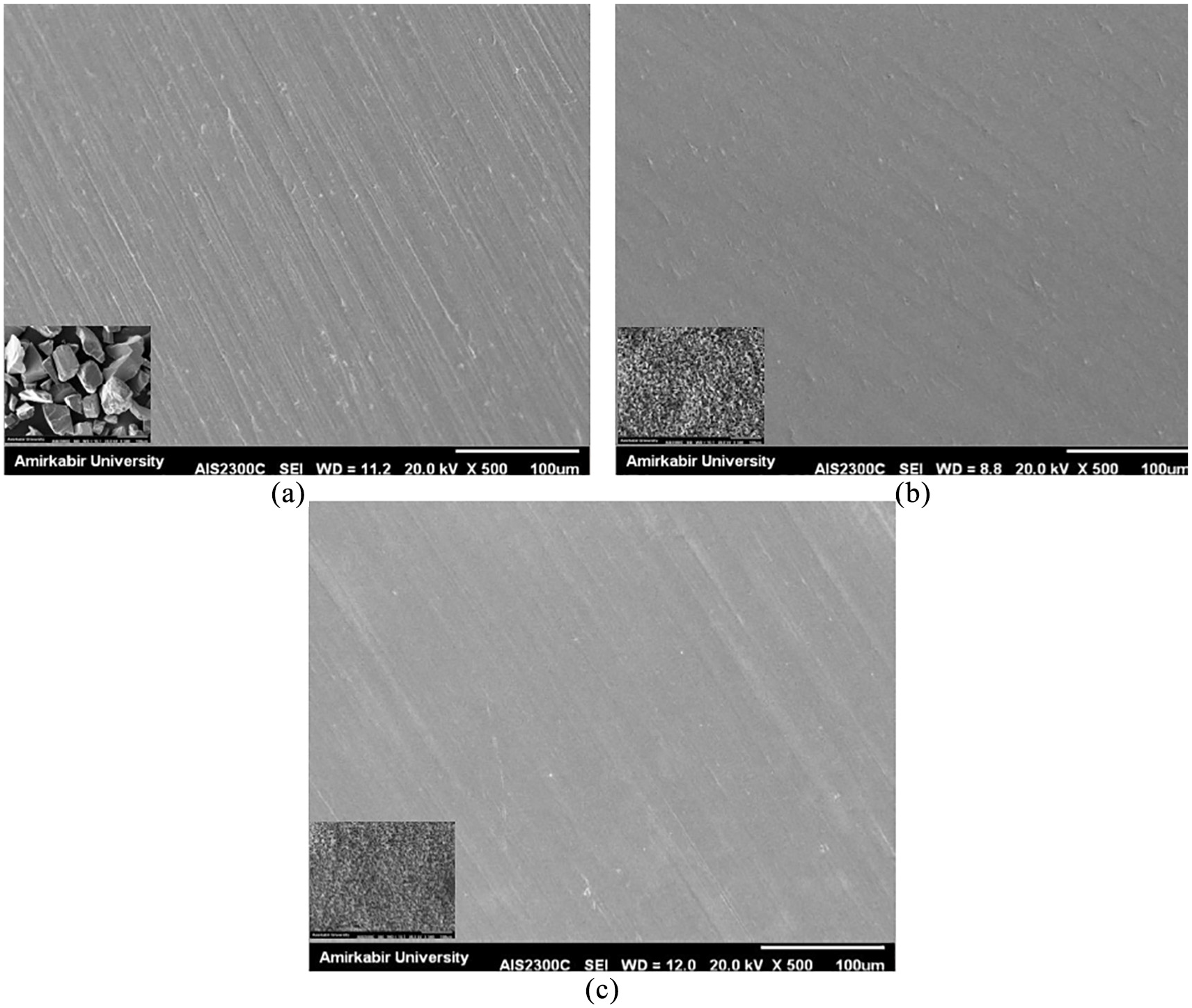
SEM images of the roughness of the femoral head surface at different mesh numbers: (a) 240, (b) 600, and (c) 1000.
Optimization
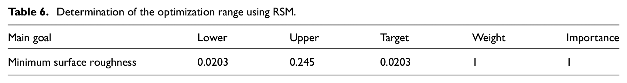
As discussed in the previous section, according to empirical findings and the ANOVA of the full factorial (Table 4) design, it was observed that the input parameters of extrusion pressure, number of finishing cycles, and the SiC abrasive mesh number have significant effects on the surface roughness of the femoral head. Therefore, these parameters should be modeled and optimized to minimize the surface roughness of the femoral head. To optimize the experimental data (Table 3) the conditions the same as those considered in the full factorial method were defined in the custom response surface methodology. Parameter optimization is aimed to achieve the least surface roughness. For this purpose, the constraints used in Table 6 were defined in the MINITAB 18 software. The weighting values and importance (in %) of the design are considered to be 1 (Table 6) which indicates the equal importance of the target values and the boundaries for the designer.
Determination of the optimization range using RSM.
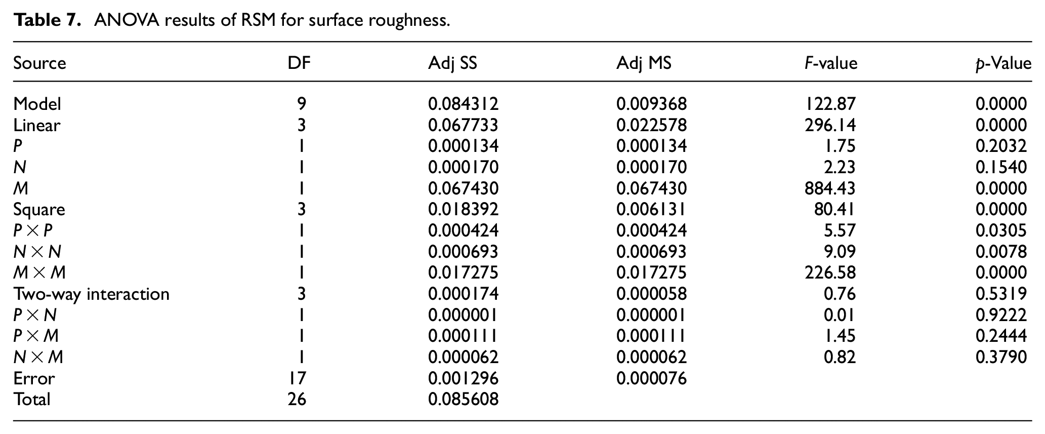
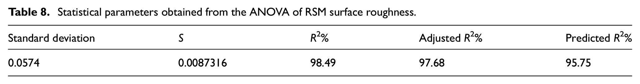
The ANOVA results of the surface roughness model are shown in Tables 7 and 8. As can be seen, the F-value, p-value, R 2 , and adjusted R 2 are 122.87, <0.0000, 98.49%, and 97.68%, respectively, confirming the significance of the surface roughness model.
ANOVA results of RSM for surface roughness.
Statistical parameters obtained from the ANOVA of RSM surface roughness.
By fitting the second-order RSM to the response function, the roughness regression model of the femoral head surface can be obtained as expressed in equation (2):
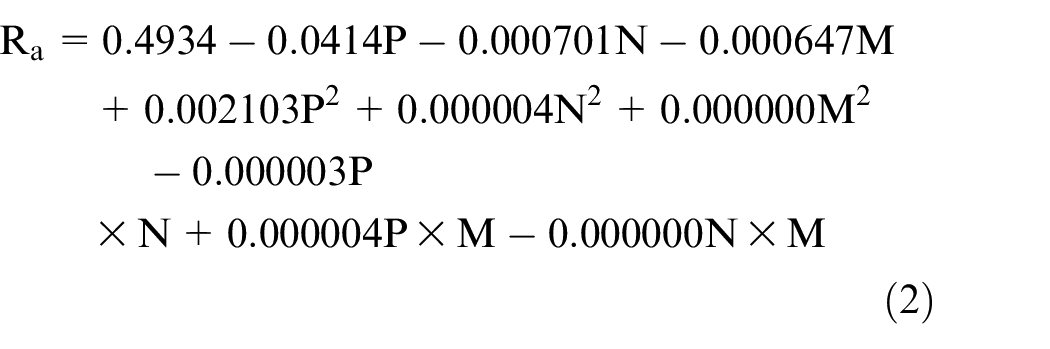
In which P, N, and M show extrusion pressure, the number of finishing cycles, and the SiC abrasive mesh number, respectively.
The optimization results using the RSM are depicted in Figure 10. Under optimized conditions (the extrusion pressure of 9.10 MPa, the number of finishing cycles of 95.45 (95 for practical use), and the SiC abrasive mesh number of 831.11 (mesh number 1000 for practical use)), the roughness of the femoral head surface was 0.0007 µm. Moreover, the desirability degree of the obtained point was 100%, implying that the optimal point can be selected as an acceptable point.
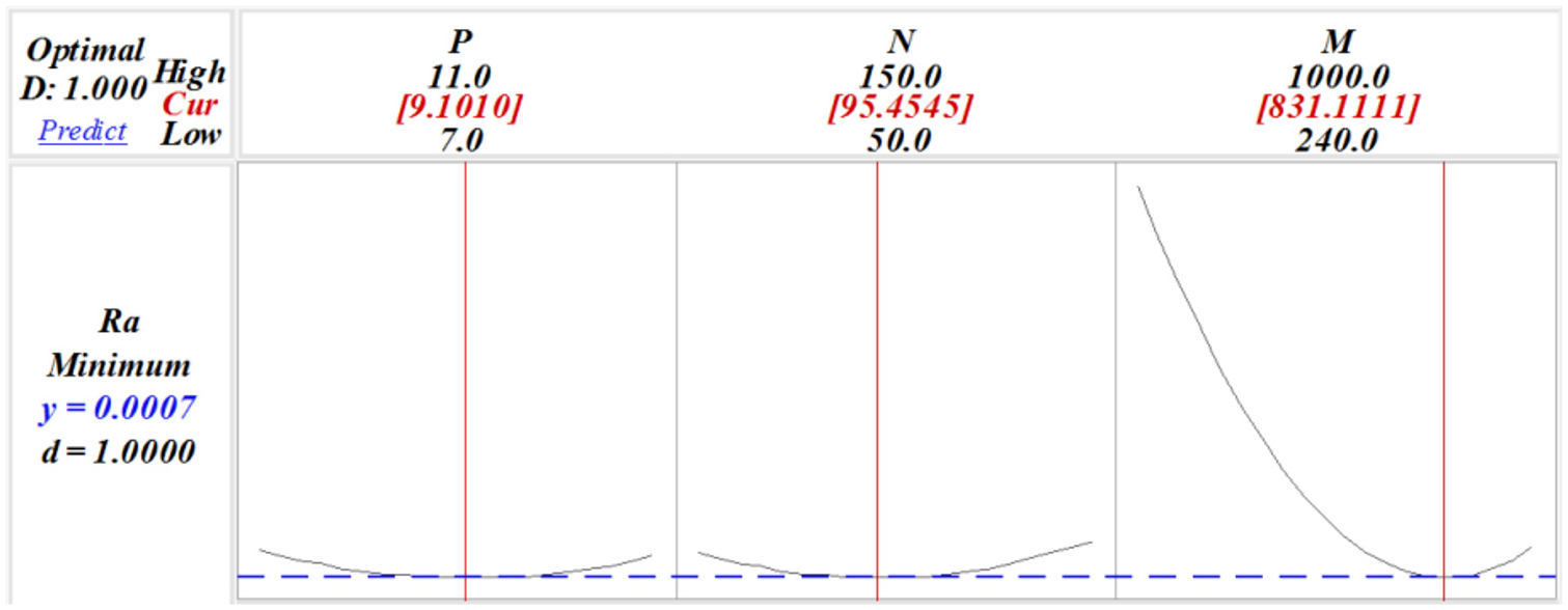
Optimization of the input parameters of the AFF process using response surface methodology.
The 3D response surface diagram for the effects of the extrusion pressure and the SiC abrasive mesh number particles on the surface roughness is depicted in Figure 11. Regarding this figure, an increase in the extrusion pressure and the SiC abrasive mesh number is followed by a reduction in the surface roughness. Furthermore, the SiC abrasive mesh number had a greater effect on reducing surface roughness.
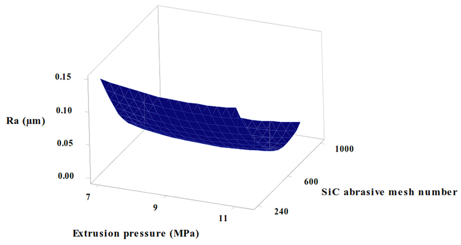
3D diagram of the response surface related to the effect of the extrusion pressure and SiC abrasive mesh number on surface roughness.
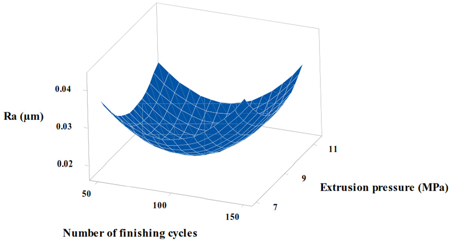
The 3D diagram of the response surface related to the effect of the number of finishing cycles and extrusion pressure on the surface roughness is presented in Figure 12. As can be seen, surface roughness decreased to its optimum value by increasing the number of finishing cycles and extrusion pressure. However, after this optimal value, an increasing trend was observed in the surface roughness. According to this figure, the lowest surface roughness was achieved by 95.45 finishing cycles (95 for practical use) and extrusion pressure of 9.10 MPa.
3D diagram of the response surface related to the effect of the number of finishing cycles and extrusion pressure on the surface roughness.
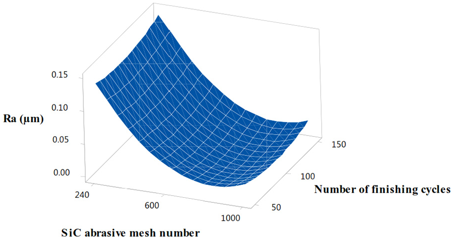
The 3D diagram of the response surface for the effect of SiC abrasive mesh number and the number of finishing cycles on the surface roughness is depicted in Figure 13. A decreasing trend can be observed in the surface roughness by enhancing SiC abrasive mesh number and the number of finishing cycles. Based on Figures 11 to 13, the improvement in femoral head surface roughness under optimal conditions is 99.71%, that is, 0.0007 µm.
3D diagram of response surface related to the effect of SiC abrasive mesh number and number of finishing cycles on surface roughness.
In the present study, the inverse replica fixture technique was used in the AFF process for automatic nano-finishing of the femoral head of hip joint implants as shown in Figure 14.
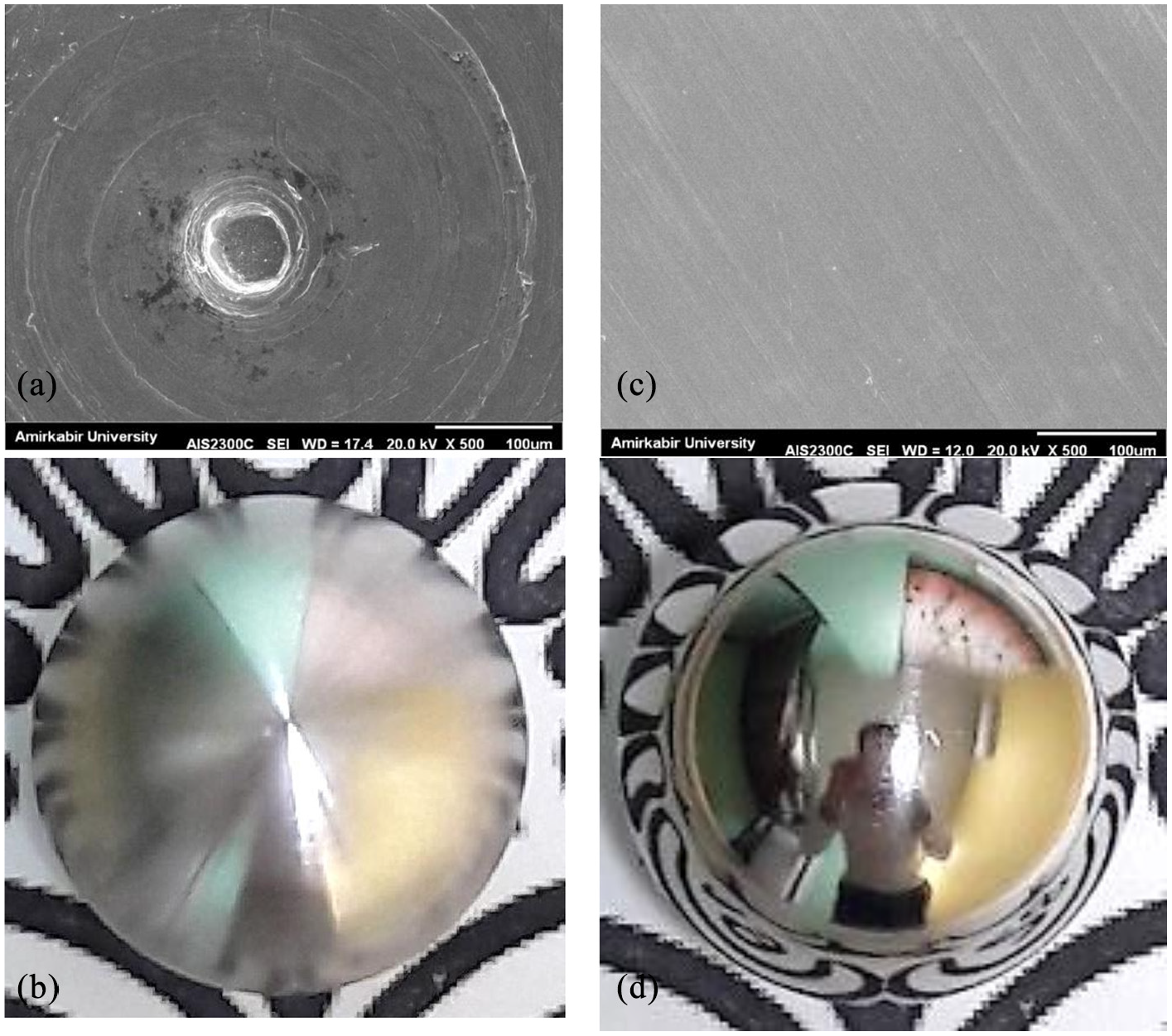
SEM images and photographs of the femoral head: (a and b) before the AFF process and (c and d) after the AFF process.
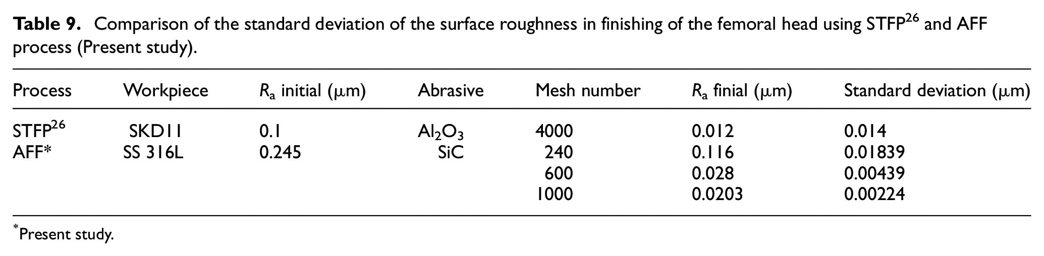
According to SEM and CMM results, the use of inverse replica fixture technique not only resulted in uniform surface roughness (minimum possible variations) up 0.0203 µm in the femoral head but also a spherical shape deviation up to 7 µm (i.e. the initial diameter in Figure 14(b), 28 mm, subtracted from the final diameter in Figure 14(d), 27.993 mm) was attained. Therefore, it can be concluded that the inverse replica fixture technique in the AFF process of hip joint implants met the requirements of the ISO 7206-2 standard 48 for offering the allowable surface roughness range (less than 0.05 µm) and shape deviation (10 µm). These findings also suggest the uniqueness of inverse replica fixture in the AFF process of femoral head automatic nano-finishing based on the surface roughness with the least standard deviation as a consequence of uniform flow by the self-deformable polishing media. For better comprehension, as shown in Table 9, the inverse replica fixture technique performed better in the AFF process in comparison with the STFP process 26 in terms of the standard deviation of surface roughness. The surface roughness is up to a range of 0.0203 µm with a minimum standard deviation of 0.00224 for the femoral head.
Comparison of the standard deviation of the surface roughness in finishing of the femoral head using STFP 26 and AFF process (Present study).
Present study.
Conclusion
In the present study, the inverse replica fixture technique was utilized for finishing the femoral head by AFF to achieve the automatic nano-finishing of hip joint implants with a diameter of 28 mm. The extrusion pressure, number of finishing cycles, and SiC abrasive mesh number were optimized using RSM to minimize the surface roughness. The results can be summarized as follows:
The ANOVA results (F-value, p-value, R2, and adjusted R2 of 122.87, <0.0000, 98.49%, and 97.68%, respectively) confirmed the significance of the surface roughness model.
The enhanced productivity and uniformity of surface roughness, and preserve the roundness of the femoral head, the inverse replica fixture technique was utilized in the AFF process through automatic finishing of the femoral head of the hip joint implants.
It was observed that the use of inverse replica fixture technique of femoral in the AFF process, through a constant speed of machining tools on the femoral head surface, not only led to uniform surface roughness (up to the range of 0.0203 µm) with the lowest standard deviation (0.00224) but also resulted in the spherical shape deviation up to the range of 7 µm in the femoral head.
The optimization results using the RSM revealed a 99.71% improvement in femoral head surface roughness (0.0007 µm) under optimized conditions under optimal conditions involving extrusion pressure of 9.10 MPa, number of finishing cycles of 95, and SiC abrasive mesh number of 1000.
Footnotes
Declaration of conflicting interests
The author(s) declared no potential conflicts of interest with respect to the research, authorship, and/or publication of this article.
Funding
The author(s) disclosed receipt of the following financial support for the research, authorship, and/or publication of this article: The authors would like to express their gratitude to Iran National Science Foundation (INSF) for supporting this research under grant number 98002696.