
Abstract
Abrasive flow machining is a pragmatic machining process used for part finishing. This article primarily focuses on the study of machining mechanism of high viscoelastic abrasive flow machining, with the aim to understand the relation among the abrasive media’s flow pressure, the material removal rate and the machining quality. The theoretical calculation models of the normal pressure on the inner surface of a circular tube and the wall sliding velocity are established based on rheology theory. The material removal rate of abrasive flow machining with a high viscoelastic abrasive media is derived. Numerical simulations with various machining conditions were conducted using the mathematical models proposed in this research and the obtained findings are discussed. The feasibility of these models introduced for high viscoelastic abrasive machining is also investigated and verified through actual experimental tests.
Keywords
Introduction
Abrasive flow machining (AFM) is a non-conventional machining process used to improve the surface finish by forcefully circulating a semisolid abrasive media over the surface to be finished. It is specifically effective and useful for parts with small holes, narrow channels, cross passages, free form surfaces, and other parts with irregular or inaccessible geometric shapes.1,2 The semisolid media for AFM is formed by mixing a carrier material, such as polymer or oil, and the abrasive particles according to a certain weight or volume ratio. In comparison with other surface finishing processes, AFM is of high machining efficiency and applicable to a wide range of materials; it can also remove burrs and round sharp corners while finishing the surface. 3 Therefore, it has been widely used in the manufacturing of dies and molds, textile machinery’s components, hydraulic valves, engine parts, other parts from critical aerospace and medical components, and mass production automobile parts. 4 AFM has been intensively studied since its invention. Rajesha et al. 5 established machining mechanism models to describe the energy consumption per unit volume and the cutting force along the tangential direction of machined surface. Using those models, the effect of a workpiece’s hardness, normal stress, the grain size of abrasive particles, machining time, and compressive pressure on the unit volume energy consumption is studied. Based on the theory stated in the literature, Gorana et al. 6 proposed both the finite element (FE) numerical analysis and the analytical approach of estimating the machining specific energy and cutting forces for the determination of cutting parameters for the inner surface of holes based on the assumption that the abrasive media is a Newtonian fluid. The precision manufacturing technology always demands a good surface finish at low cost. This scenario drives both industries and research community to develop novel finishing processes. In the present experimental endeavor, an attempt is made in the direction of developing a new media based on viscoelastic carrier and its characterization for fine finishing through AFM process. Research by Howard and Cheng 7 is made in the direction of developing a new media based on viscoelastic carrier and its characterization for fine finishing through AFM process. The newly developed media was again characterized through rheological properties. It is found that temperature, shear rate, creeping time, and frequency have impact on rheological properties, and the percentage of ingredients of media governs trends of their relations. Kenda et al. 8 investigated the influence of the process parameters and AFM media pressure on surface integrity of a hardened tool steel. It is shown that AFM is capable to remove the electrical discharge pre-machined (EDM) surface that is damaged and results in satisfying surface roughness. Moreover, it induces high compressive stresses in a very thin sublayer of approximately 10 μm. Kar et al. developed a new media based on a viscoelastic carrier and its characterization for fine finishing through AFM process. The newly developed media was again characterized through rheological properties. It is found that the temperature, shear rate, creeping time, and frequency have impact on rheological properties, and the percentage of ingredients in the media’s governs trends of their relations. 9 Tang et al. 10 investigated how the pressure of the abrasive flow influences the machined surface’s finish, and they concluded that a larger pressure difference at the inlet and the outlet improves the machining productivity and surface quality. However, there are no rheological model and machining model that are able to quantitatively describe the AFM process for the high viscoelastic abrasive media. There is a great necessity to establish an appropriate process model of AFM to reveal the machining physics, so the AFM with high viscoelastic abrasive media can be well controlled for a better surface finish and reasonable productivity.11–13 It is known that AFM machining is a complicated material removal process by numerous hard and irregularly shaped abrasive particles. This process is affected by many processes parameters including the ratio of abrasive particles to its carrier material of the media, abrasive particle size and its mechanical properties, the number of machining cycles or machining time, the flow rate of the media, and the media flow pressure.
This article primarily focuses on the study of machining mechanism of high viscoelastic AFM. The ultimate goal is to establish the relation between the media’s flow pressure in both the normal and the longitudinal direction of the inner surface of a circular tube and the material removal rate, as well as the machining productivity and quality. The viscoelastic element’s stress state is analyzed using rheological theory for a high viscoelastic abrasive media; the pressure variation and the wall sliding velocity model for a tube’s inner surface AFM are proposed; then the material removal rate is calculated using the Preston equation. MATLAB is used to conduct the numerical simulation and analysis for the pressure distribution, the wall sliding velocity, and the material removal rate. A number of AFM experiments were also carried out to verify the effectiveness of the high viscoelastic abrasive media and the feasibility of the proposed material removal rate estimation approach.
High viscoelastic abrasive media for AFM
A high viscoelastic abrasive media (VLFA-I) investigated in this research is a mixture of a polymer material and abrasive particles previously developed by the authors of this article at the Abrasive Flow Machining Center of Taiyuan University of Technology. 14 The polymer material plays a role as the carrier of abrasive particles. Figure 1(a) shows the high polymer material at the room temperature. Figure 1(b) shows the shape of high viscoelastic abrasive media right after it is extruded out from a set of holes.
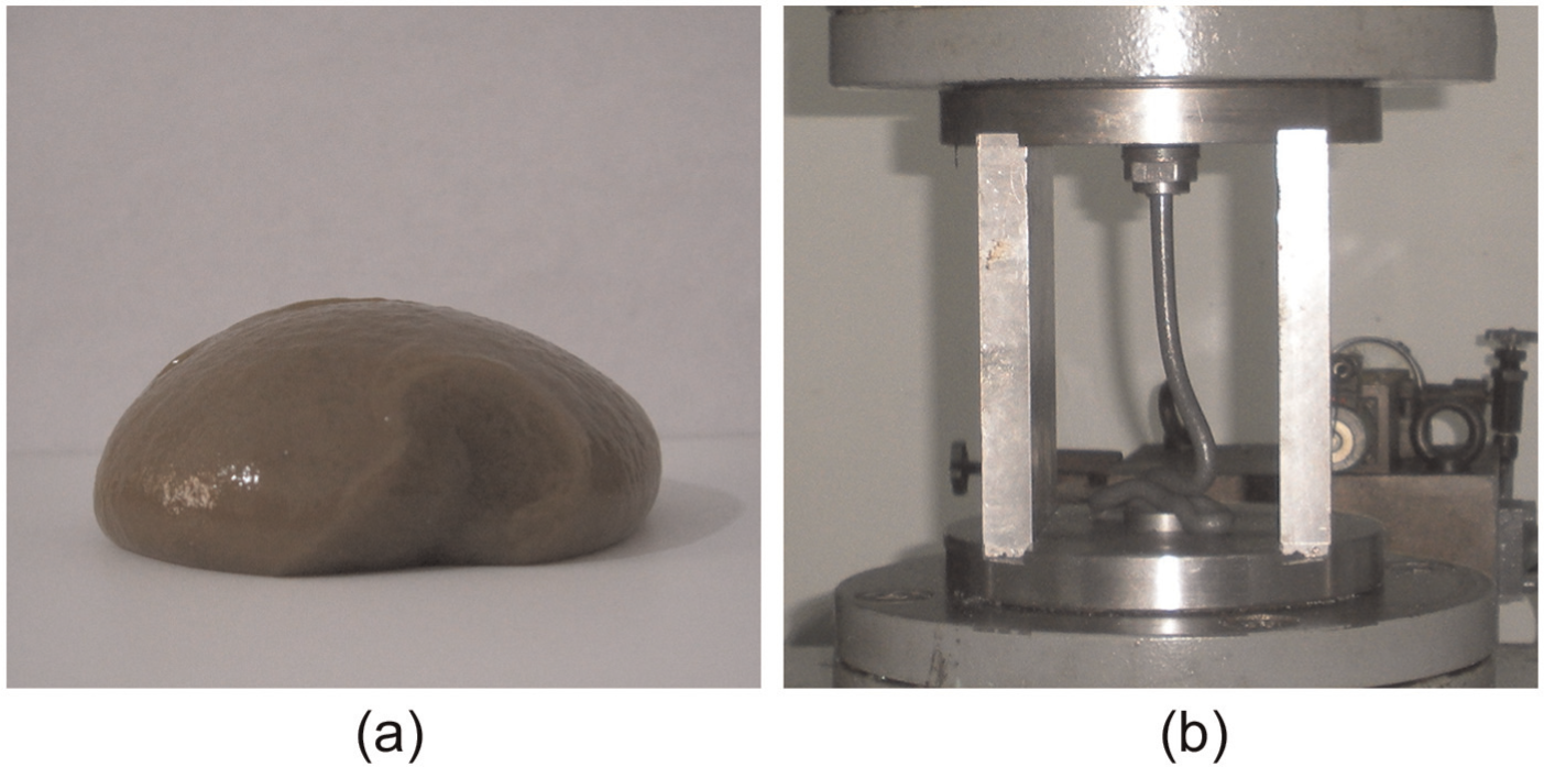
Polymer carrier and flow state of extruded abrasive media: (a) carrier at the room temperature and (b) flow state of extruded AFM media.
It is known that the abrasive carrier’s apparent viscosity is related to the working temperature, whose variation trend is measured as shown in Figure 2. It is found that the abrasive media with the polymer material as its carrier used in this research is of a high viscosity at a low temperature. The apparent viscosity decreases exponentially with the increase in the shear rate up to a shear rate of 20/S; then it displays no dramatic change with the shear rate variation. The apparent viscosity is estimated by dividing the shear stress with the corresponding shear rate. As the temperature rises, the polymer material molecule’s random motion intensifies and the molecular segment activities become easier. This results in a decrease in the shear rate for the abrasive carrier. Note that when the viscosity of the abrasive carrier decreases, the abrasive particles are less restrained by the polymer material or the particles are less coerced by the base material during the extrusion. Consequently, the abrasive carrier exhibits “shear-thinning” characteristics. It is also found that the high viscoelastic abrasive media expands at the outlet, and its pressure is not 0 based on the observed results shown in Figure 1.
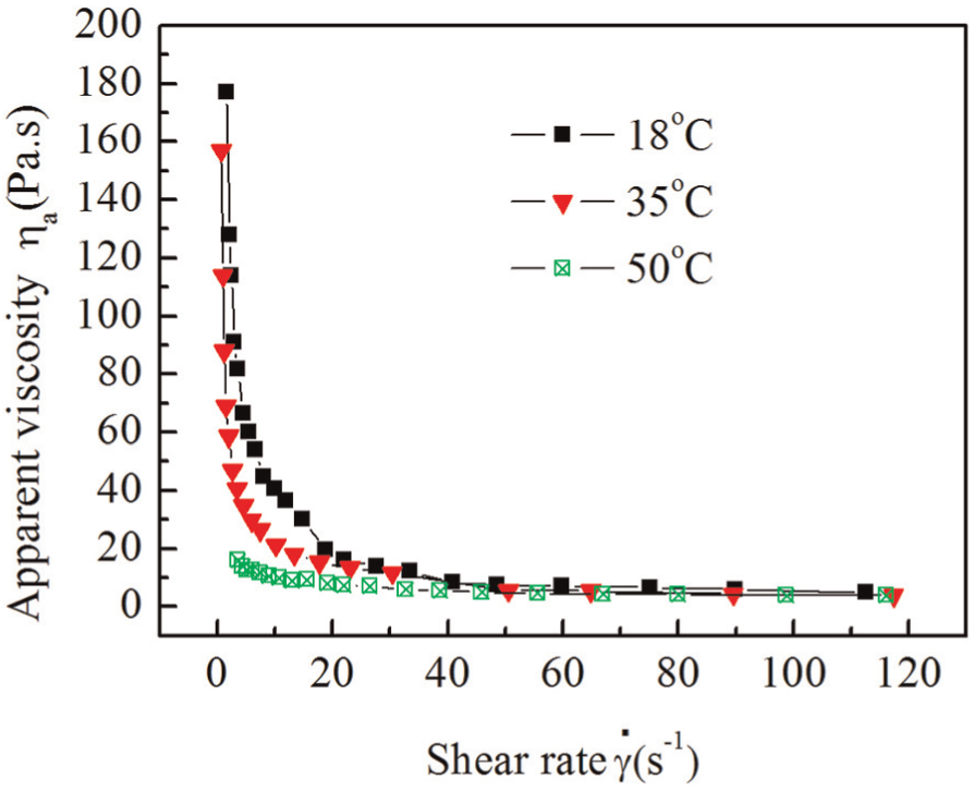
Viscosity variations in the abrasive media at different temperatures.
This means that the abrasive media made of the abrasive particles and the polymer material is of “elastic” property, which differs from the conventional “soft” abrasive media. Due to the elasticity, the abrasive media undergoes a volumetric contraction due to the applied pressure in the extrusion channel. Once the pressure is reduced or released, the abrasive media tends to recover the elastic deformation in the form of expansion.
In this research, we prepared three types of high viscoelastic abrasive media with the same mixing ratio, but with different particle grit size. The abrasive particle’s grit size for three mixtures is 80, 100, and 120, respectively. The mass ratio of the polymer material (type: VLFA-I) to the abrasive particles is 1:1. The research done by Han et al. 15 provides a method to estimate the abrasive’s pressure variation in the normal direction at the outlet area. In this research, the pressure change in the normal direction was obtained dθ with different shear stresses, through measuring the pressure using the sensors at the outlet of a cylindrical tube. The obtained results are shown in Figure 3. From Figure 3, the abrasive media made of the mixture of the high viscoelastic polymer and the abrasive particles possess high elasticity; meaning a larger shear stress corresponds to a larger difference of the normal stress/pressure. The elasticity of the polymer material is evaluated using the first normal pressure difference. A larger difference in terms of the normal pressure corresponds to a media with a higher elasticity. An abrasive media with a high elasticity is of high productivity. It is also found that the abrasive media with a small particle grit size possesses a higher elasticity. The physics behind this fact is that for different abrasive media with the same mass ratio, the number of abrasive particles is larger with a smaller particle’s grit size. A smaller size particle causes less resistance for the polymer segment’s deformation or recovery. Therefore, the elastic deformation’s recovery with smaller grit abrasive particles becomes easier and the abrasive media exhibit a larger elasticity. This also features the difference of the abrasive media under the study with respect to the “soft” abrasive media, which is elastic. The high viscoelastic abrasive media is considered as a “deformable grinding tool” conducting the material removal when it is extruded over the work surface.
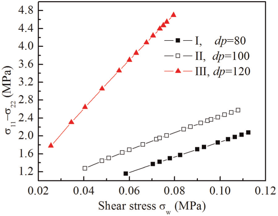
Normal pressure variation in three abrasive media.
Process modeling of high viscoelastic abrasive media
Normal stress of high viscoelastic abrasive media
For an arbitrary small stress element extracted from the abrasive media close to the inner wall of a circular tube, its stress state is shown in Figure 4. z-Axis is in the media’s flow direction; r-axis is in the radial direction; θ-axis is in the tangential direction of the tube. T11, T22, and T33 are designated as the normal stress components of the stress tensor along z-, r-, and θ-axis, respectively. Based on the high polymer rheological theory, 15 the first normal stress/pressure difference is estimated as follows

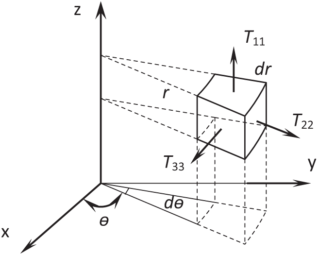
Stress tensor of stress element close to the wall.
Set the first normal stress difference as N1

Using the theory stated in the literature developed by Han et al., 15 the first normal stress difference around the region of the circular tube’s outlet is derived as follows
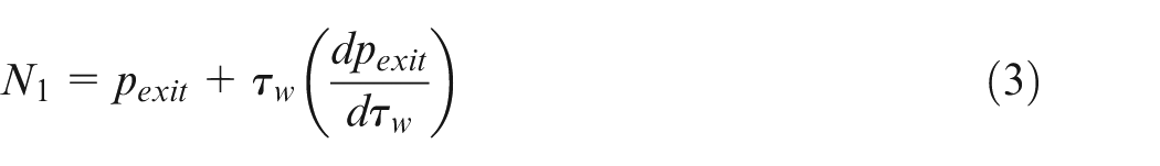
where τw is the shear stress exerted on the abrasive media close to the wall;

Using equations (3) and (4)
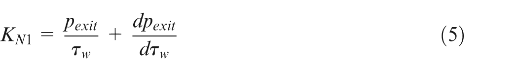
For a small abrasive media element located nearby the tube’s inner wall, let T11 = p and T22 = pw, from equations (2) and (4), the following relation as stated in equation (6) can be established

Here, p represents the abrasive media’s pressure in z-direction, which is the abrasive media’s flowing direction. pw represents the pressure in the radial direction of the circular tube, which is also the normal direction of the tube’s wall.
Cutting factor of AFM
It is known that the abrasive media per kilogram contains up to 108–109 particles under the condition that the weight mixing ratio of the abrasive particles and the carrier falls in the range of 40%–60%. Each of the particles acts as a cutting tool to plow the work surface while flowing over it under pressure. Abrasive particles contacting the surface of the inner wall of the tube interact with the workpiece very differently due to their shape, size, and momentary orientation. It is difficult to analyze the material removal process by simply postulating one particle’s cutting mechanism; the AFM physics has to be studied macroscopically. The calculation model of cutting force for a micro abrasive media element is illustrated in Figure 5. Assume that this element is located close to the work’s surface. Its contact area is designated as ds; the normal pressure in the radial direction is pw; the shear stress (viscous force) between the wall (work surface) and the micro abrasive media element is τw; KT is the introduced cutting factor of AFM. So, the reaction force exerted on the micro abrasive media element

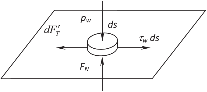
Force analyses for a micro abrasive media element.
The abrasive media consisting of the carrier and particles is forcefully circulated to flow, and this flow includes two phases. The force exerted on the particle phase for a two-phase flow is influenced by the number of process parameters including the Reynolds number (Re), the flowing rate difference between the carrier and particles (Δu), the pressure gradient (∇p), the particle’s grain size (dp), the geometric shape of particles (φ), and the number of abrasive particles interacting with the work’s surface.
This number is related to the mixing ratio (ψm) of the carrier and abrasive particles. In addition, the work’s hardness (Hw) is related to the depth of cut of the particles due to the experienced pressure in the radial direction; the work-in-progress surface roughness (Ra) also affects the cutting force. Therefore, the cutting factor can be considered as a function of multiple variables shown in equation (8)

In equation (8), variables Re and Δu are the parameters related to the abrasive media’s flow behavior; dp, ϕ, and ψm are the parameters related to abrasive particles; and Hw and Ra are the parameters related to the workpiece’s mechanical properties and the surface roughness, respectively. Obviously, it is difficult to analytically derive an equation to estimate the cutting factor by incorporating all parameters listed in equation (8). Rearranging variables in equation (7), the cutting factor can be estimated as follows
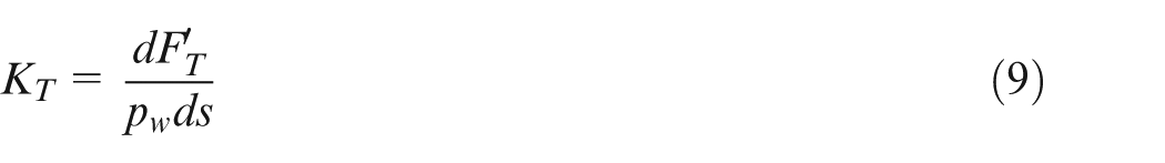
The shear force exerted on the abrasive media is equal to the reaction force applied on the work surface during the machining process when the sliding between the work surface and the abrasive media takes places. For a static flow, the shear force on the micro abrasive media element is calculated by

Substituting equation (10) into equation (7), the shear stress is obtained by the following equation

Based on the previous analysis, the cutting factor KT is related to different process parameters, which makes it hard to obtain quantitatively. However, equation (11) provides an alternative and practical means to find the cutting factor KT using the measured pressure in the radial direction of the work surface and the shear stress on the work surface through conducting experiments.
Pressure exerted on abrasive media close to the wall
The flow model of abrasive media for the inner surface machining of a hole is illustrated in Figure 6. The cylindrical coordinate system is introduced for the following analysis.
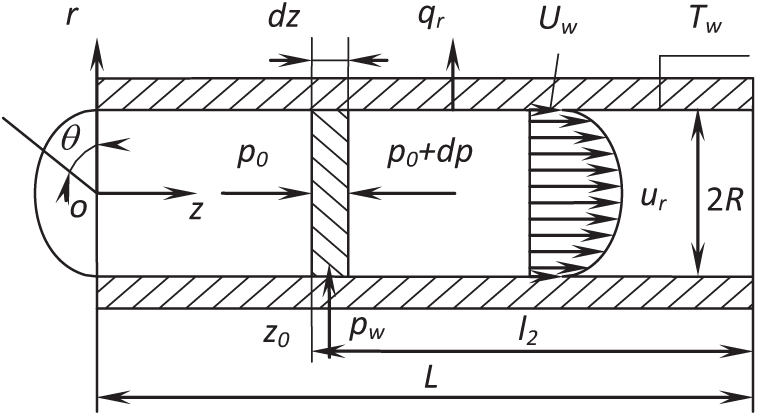
Flow model of abrasive media in a circular tube.
According to the fluid mechanics, the continuity equation is described as
The shear stress on the abrasive media at an arbitrary element is expressed as follows
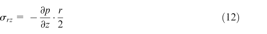
So, the shear stress on the inner surface of the tube (r = R) is calculated using the following equation
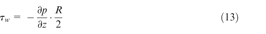
For a stable-state flow, the machining force applied on the inner wall surface balances the shear force applied on the abrasive media. Substituting equations (6) and (13) into equations (11), equation (14) can be derived

In equation (14), KT represents the cutting factor between the abrasive media and the inner wall surface. If the resultant pressure force p0 in the direction flow at z = z0 is given, the pressure force on the inner surface in the radial direction of the tube is assumed as pw. Conducting the integration for both sides of equation (14), we have the following equation
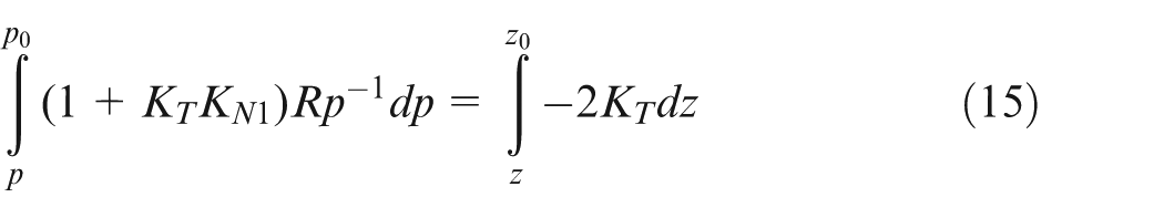
The normal pressure from z0 to z can be derived as equation (16)
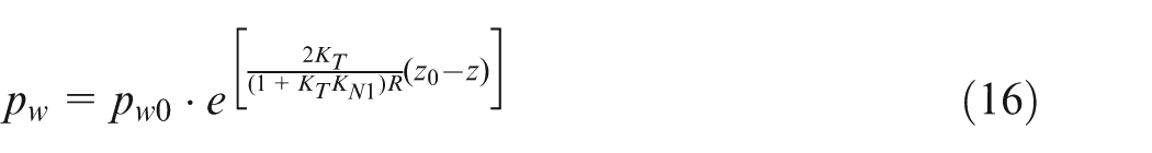
The pressure gradient in the direction of abrasive media flow is estimated as follows
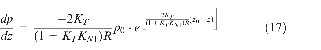
From equation (17), it is found that the pressure gradient varies in the direction of abrasive media flow.
Flow velocity of the abrasive media adjacent to the inner surface
The abrasive media flow can be considered as the characteristic of power-law fluid; 15 its constitutive equation is described as

In the above equation, the rate of shear is
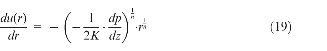
Conduct the integration for equation (19) and set the wall sliding velocity to be uw = u(R)
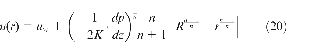
The flow (Q) in the circular tube can be calculated using the above equation. Substituting equation (17) into equation (20), the sliding velocity on the inner wall of the circular tube can be obtained by equation (21)
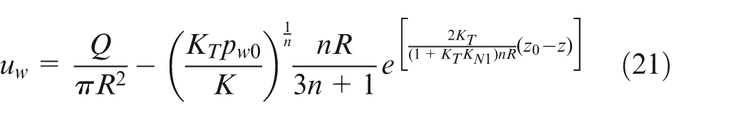
It is found from equation (21) that the sliding velocity of the abrasive media on the inner wall of the circular tube is related to the flow rate, pressure, viscosity, and cutting factor, as well as the first normal stress difference.
Material removal rate of AFM
In this research, the material removal rate (Dt) is defined as the depth of cut at unit time in the normal direction of the work surface; in the case of the circular tube, Dt is the depth of cut in the radial direction of the inner wall. Referring to the research 16 and using equation (16) derived in this research for normal pressure estimation and the sliding velocity of the abrasive media with respect to the stationary wall estimated by equation (21), the material removal rate per unit time can be calculated by equation (22)

In equation (22), Dt is the depth of cut defined as the material removal rate at the unit of millimeter per second; pw is the normal pressure (MPa) at the location under the study; uw is the relative sliding velocity (mm/s) of the abrasive media; kd is the factor which relates to the depth of cut, which is determined through experimentation.
Simulation of high viscoelastic AFM
Simulation of the wall sliding velocity
Using the abrasive media flow model proposed previously, the influence of the rate of abrasive flow at the specific viscosity on the wall sliding velocity is calculated and its results are plotted in Figure 7. It is found that the wall sliding velocity increases in the direction of abrasive flow; it reaches its maximum value when it approaches the outlet of the tube. The rationale behind this is that the resistance force on the abrasive flow decreases as it reaches the exit area. When the abrasive media flow rate is 12,861 mm3/s, the wall sliding velocity is 0 near the inlet of the tube and then gradually increases as shown in Figure 7. This means that there is no AFM taking place under this condition.
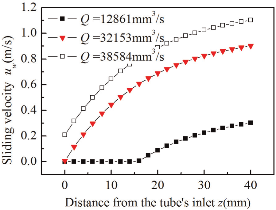
Effect of the flow rate on sliding velocity at different locations.
The wall sliding velocities with different viscosities at an identical rate of flow are different. Figure 8 shows the wall sliding velocity for three different abrasive media. It can be seen that with the increase in the viscosity K, the wall sliding velocity increases rapidly. When the viscosity reaches a certain level, for instance, K = 12502 N s/m2, the wall sliding velocity is almost the same as the average flow velocity of the abrasive media. The abrasive media behaves as a deformable grinding tool with a large amount of abrasive particles embedded on its outer surface which conduct the removal of the material.
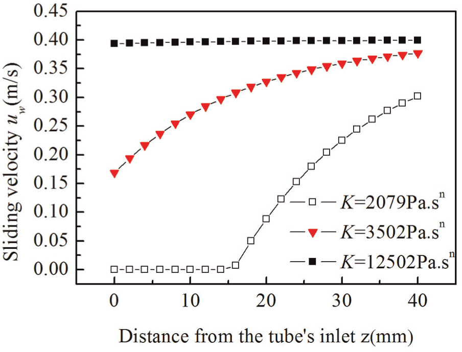
Effect of abrasive media’s viscosity on the wall sliding velocity.
Therefore, the viscosity of the abrasive media has a significant effect on the wall sliding velocity, consequently the material removal rate. The abrasive media with a higher viscosity can reach a high wall sliding velocity, which results in a higher material removal rate and a high productivity. The viscosity is directly related to the apparent viscosity, so the above-mentioned results also demonstrate how the surface finish action is affected by the apparent viscosity.
Simulation of the pressure on the inner surface of the circular tube
Using equation (16) derived in the previous section, the normal pressure on the inner surface of the tube in the radial direction can be estimated for different abrasive media with different elasticities. The calculated results are shown in Figure 9. As seen in Figure 9, the normal pressure in the radial direction of the inner surface of the machined tube is not a constant; it instead decreases exponentially in the flow direction of the abrasive media. The pressure at the inlet of the tube is approximately two times higher than at the outlet of the tube. It is also found that the normal pressure decreases less for the abrasive media with high elasticity in comparison with the one of low elasticity. It is known that the normal pressure is relatively low at the outlet of the tube for a “soft” abrasive media or an abrasive media of no elasticity.
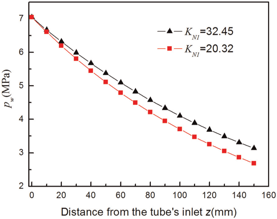
Pressure change in the direction of the abrasive media flow.
The fact that the abrasive media with a high elasticity is able to keep a certain level of normal pressure around the outlet region of the tube implies that it is able to machine the entire tube with relatively the same machining conditions. It results in a better dimensional machining accuracy because the material removal rate across the tube from the inlet to the outlet varies less in comparison with the “soft” abrasive media.
Simulation of material removal rate
Using equation (22), the material removal rate is numerated for two circular tubes with the inner diameters of Dg1 = 9.864 mm and Dg2 = 7.882 mm, respectively. Both the tubes have a length of Lg1 = 29.96 mm. The abrasive material’s properties under the room temperature (20°C) are K = 33209, n = 0.2950, and KN1 = 20.32. The parameters of AFM machine used to conduct the experiments as shown in Figure 11 are z0 = 135 mm, pz0 = 3.4 MPa, and Q = 63280 mm3/s. The calculated material’s removal rate is shown in Figure 10. The simulated results show that the material removal rate decreases along the direction of the tube, which agrees with the results obtained in the previous section. This is the reason that the AFM-machined tube is of tapered shape in its inner surface. Examining Figure 10, it is also observed that the material removal rate for two tubes with different inner diameters varies. The material removal rate is smaller for a tube with a larger diameter, and the machining efficiency is relatively low. Meanwhile, the variation in the material removal rate along the abrasive media flow direction of the tube is also small. When the diameter is 9.864 mm, the material removal rate changes from approximately 1.0 to 2.4 mm/s, whereas it varies from 1.5 to 4.7 mm/s for a machined tube with a diameter of 7.882 mm. These results reveal that the AFM’s surface finishing and dimensional accuracy can be controlled by adjusting the machining parameters for different size’s parts based on the equation proposed in this article.
Material removal rates with different size’s tubes.
Experimental study of high viscoelastic AFM
Experimental setup
Figure 11 shows the AFM system used for experimental study in this research. This AFM system includes a number of pressure, temperature, and force sensors as well as a supplementary channel. This channel is used to accommodate the part to be machined. A number of important process parameters are listed in Table 1. The Type I high viscoelastic abrasive material, 17 developed at the Center of Abrasive Flow Machining in Taiyuan University of the Technology, is chosen for the experiments. A circular steel tube (Carbon steel #45) with an inner diameter of Dg1 = 9.864 mm and a length of Lg1 = 29.98 mm is used as the test part. It is machined by turning operation on a lathe. Its inner surface’s roughness is measured using TR200 Surface Profiler (Advanced Technology Inc.) as shown in Table 2. Its original diameters of the inner surface at different locations are also measured as illustrated in Figure 12. After each machining cycle, the surface roughness and the diameters at different locations across the tube are measured to evaluate the machining performance. The abrasive media are bi-directionally extruded through the tube in this research and a large number of experiments were conducted.
Experimental AFM system setup: (a) experimental device drawing and (b) experimental device.
Experimental AFM media (20 °C) and machining condition parameters.
Surface roughness of AFM-machined surface.
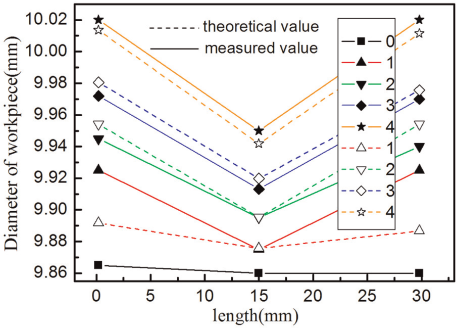
Diameter variation with different machining cycles.
Experimental results and analysis
The change in diameter of the tube and the surface roughness variation in the inner surface of the finished tube are measured at three positions located nearby the inlet, the midpoint, and the outlet area. Figure 12 shows the measured diameters at three locations that correspond to different machining cycles through experiments. In order to compare the measured and simulated diameter variation, the results obtained through simulation are also plotted in the same figure. At Position 1, which is located at 1 mm from the inlet, the diameter increases by 60 μm for the first machining cycle; the diameter increased by 1.6% from 9.86 to 10.02 mm after four machining cycles. The diameter variation is up to 0.155 mm. Position 2 is located in the midpoint of the tube; its diameter increase is 0.09 mm. The increase in diameter at Position 3 is almost the same as Position 1. Obviously, the increase in the diameter after AFM at the inlet and outlet area is much larger than that in the midpoint of the tube. This is because the abrasive material is extruded bi-directionally in this experiment, so the material removal rate at the two ends are the same. The normal pressure around the mid tube area is smaller than the inlet area, so the material removal rate is relatively lower.
In this research, the abrasive media that is extruded passes through the circular tube reciprocally. The tube’s diameter changes the most after the first machining cycle. The increase in diameter is about 60 μm. After four machining cycles, the diameter of the circular tube changes from 9.86 to 10.02 mm. The diameter variation is 0.16 mm corresponding to 1.6% size increase. Examining the difference between the simulation results and experimental data, it is found that the discrepancy for the first machining cycle is 38 μm, which is relatively large in comparison with the rest of three machining cycles from Figure 12. The reason is that the theoretical simulation does not include the cutting marks or burrs on the inner surface. After the first AFM cycle, the burr or cutting marks are removed. The simulation and measured results agree with the flow model suggested for high viscoelastic abrasive media and it is feasible to describe its AFM behavior.
A cone shape forms at the ends of the tube, and with the increase in the machining cycle, the taper of the cone increases. This is because the material removal rate at the inlet region is large for each extrusion in one direction. Since the wall sliding velocity does not change drastically, the decrease in material removal rate is mainly caused by the pressure drop. In order to keep the machined tube’s diameter relatively constant after the AFM with the high viscosity abrasive media, the extrusion pressure on the abrasive media needs to be reduced. Note this will reduce the machining productivity. The measured surface roughness (Ra) at different locations is listed in Table 2. From Table 2, the surface roughness is improved with the increase in the machining cycles or machining time. The average change for four different location’s surface roughness value is 1.067 μm after the first machining cycle is completed, 0.367 μm after the second machining cycle, and 0.327 μm after the third machining cycle. Compared to the original surface prior to AFM, the surface roughness is greatly improved. Therefore, the high viscoelastic AFM is also an efficient and effective method to improve the surface finishing. It is also noted that the average surface roughness worsens after the forth machining cycle, which implies that there is a limited capacity for improvement of the surface finish by employing high viscoelastic AFM process.
From Table 2, it is also understood that the first machining cycle is most effective in terms of the surface finishing improvement. It is interpreted that the AFM during the first machining cycle removes the high points of the machined surface created in the previous manufacturing process, so the surface roughness is largely improved in comparison to the subsequent machining cycles. If the efficiency of surface finishing is defined as the product of surface roughness change per unit time and the finished surface area, the machining efficiency is 334.9% for the first cycle, 89.1% for the second cycle, and 65.2% for the third cycle.
Shiming et al. 18 conducted the surface finishing’s efficiency study for a “soft” abrasive media. It is made of oil and SiC particles, which has an average diameter of 50 μm. The extrusion pressure at the inlet is 3 MPa for a steel tube. It took 50 h to finish a surface with an area of 2200 mm2. The surface roughness (Ra) is improved from 0.566 to 0.271 μm. The surface efficiency is 0.361%. The efficiency of high viscoelastic AFM introduced in this research is much higher than that of the “soft” AFM.
Figure 13 shows the inner surface’s microscopic images before and after the AFM with four machining cycles. The abrasive flow media is extruded in the z-direction. It is found that the cutting marks after the turning operation are obvious and coarse and the cutting mark’s texture is aligned perpendicular to the abrasive media flow direction. After the AFM, the cutting marks originating from the turning operation disappear and the surface becomes much smoother as shown in Figure 13(b). Therefore, the high viscoelastic AFM is an effective and efficient machining method to improve the surface finish.
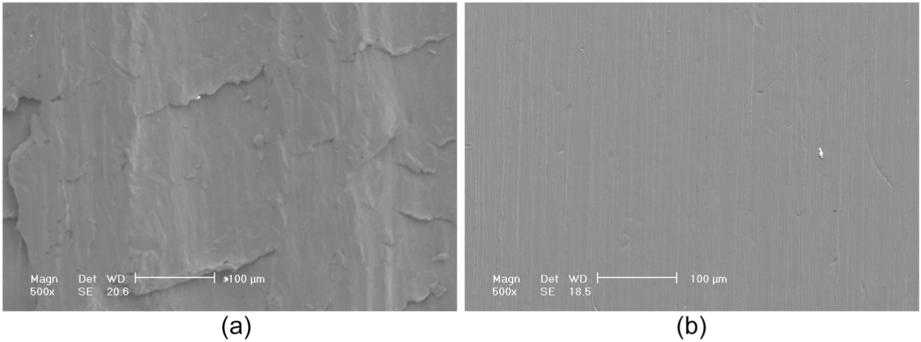
Comparison of surface SEM images: (a) before AFM and (b) after AFM.
Conclusion
In this article, the machining mechanism of high viscoelastic AFM is studied; the calculation model of the normal pressure on the work surface and the wall sliding velocity is established; and the material removal rate is derived. Numerical simulation was conducted by use of the mathematical models proposed in this research for various machining conditions. The feasibility of the models introduced was verified through machining experiments. The following research results are obtained:
A high viscoelastic AFM resembles a grinding process with a deformable grinding tool; the properties of introduced semi-fluidic abrasive media in this research depend on the mixing ratio of the polymer carrier and abrasive particle and its size. The wall sliding velocity is related to the abrasive media’s properties, and with the increase in the abrasive flow and viscosity, the wall sliding velocity increases.
The material removal rate decreases in the direction of the abrasive flow, which creates a taper at the inlet area of the circular tube. The taper can be controlled by adjusting the process parameters such as the normal pressure which is associated with the elasticity of the abrasive media.
A relatively constant normal pressure maintained in the tube results in less variation in the material removal rate. Consequently, the machined tube’s diameter at different locations in the longitudinal direction varies less. This is beneficial for dimensional accuracy of the machined tube.
The surface finish of the workpiece can be improved by employing high viscoelastic AFM, and it is also very efficient.
Footnotes
Declaration of conflicting interests
The authors declare that there is no conflict of interest.
Funding
This research received no specific grant from any funding agency in the public, commercial, or not-for-profit sectors.