
Abstract
A modified Zerilli–Armstrong model has been proposed and validated in previous works for simulating distinct deformation mechanisms of continuous-shear and shear-localization during severe plastic deformation of a face centered cubic alloy. In this paper, the validity of the modified Zerilli–Armstrong model has been further tested by using it for modeling the severe plastic deformation of another face centered cubic material, a steel alloy. In particular, the modified Zerilli–Armstrong model is used as a constitutive relation for simulating behavior of AISI 1045 steel alloy while undergoing severe plastic deformation through orthogonal and plane-strain machining. Accordingly, the performance of the constitutive relation in predicting flow stress distribution along the primary shear zone is validated by comparing with forecasts made using the distributed primary zone deformation, the original Zerilli-Armstrong and Johnson-Cook models. Furthermore, finite element simulations of orthogonal cutting of this steel alloy were carried out, and good agreement was observed between the predicted chip morphology and attendant cutting forces with experimental values reported in literature for a range of cutting conditions. The force predictions also fared better compared to those predicted by using the Zerilli-Armstrong and Johnson-Cook models. These validations provide further corroboration of using the modified Zerilli–Armstrong model as a constitutive relation for simulating the behavior of face-centered cubic materials under conditions of high plastic strains and also high strain-rates.
Keywords
Introduction
Machining is a major manufacturing process that has significant impact on a nation’s development and economy. It has been estimated that metal cutting operations in the developed world contribute about 5% of its gross domestic product (GDP). 1 Despite its significance and many years of machining-related research, there is no complete understanding of the underlying physics of deformation that would help in choosing optimal cutting conditions, and industry still relies greatly on an operator’s experience and empirical testing for apt cutting conditions, which is time consuming and expensive. 2 This is due to the intricate physics of metal cutting processes comprising machining and abrasive techniques. Hence, there is a need for a suitable technique for modeling machining, which would aid in understanding the deformation occurring during the process.
The finite element (FE) method is a powerful numerical modeling tool, and it has been used to simulate severe plastic deformation (SPD) occurring during the metal cutting process. FE modeling of the metal cutting process is a challenging task due to the extreme strains, strain rates, and temperatures encountered by the material in a narrow deformation zone. FE modeling therefore requires an accurate constitutive model describing the thermo-visco-plastic behavior of the material at high strains, high strain rates, and higher temperatures for conducting realistic simulations to generate authentic predictions. 3
The constitutive models are broadly classified based on the methods of derivation and calibration as physics-based, empirical, and semi-empirical. The physics-based models are derived using deformation theory, and they can accurately describe the material behavior for a wide range of strain rate and temperature.4–10 Such physics-based constitutive equations are mechanical threshold stress (MTS) models derived using interaction mechanism of dislocations with obstacles 4 and the Preston model which includes dislocation drag effects. 5 Similarly, Melkote et al. 6 and Liu et al. 7 have also proposed physics based models for simulation of orthogonal cutting of titanium and copper respectively. However, these models are not widely used because of the difficulty in calibration that requires data from precisely controlled experiments for a large number of constants compared to empirical and semi-empirical models.11,12
The empirical models are calibrated by fitting the equation to experimental data obtained from mechanical tests. Because of their empirical nature, they exhibit limited flexibility but are widely used due to their simplicity and the availability of constants for a wide range of materials and, due to their availability as standard constitutive laws in various commercial FE codes. 13 The Johnson–Cook (JC) model 14 is the most popular representative of empirical relations that does not consider the influence of the coupled effects of strain and temperature and of strain rate and temperature. 15 The JC model has been applied for describing the material behavior of various metals and alloys under various strain rates and temperatures.8,11–13,16,17 The semi-empirical models are derived based on the physics of deformation, but their constants are identified by fitting the equation, as in empirical models, to experimental data. Among the semi-empirical models, the Zerilli–Armstrong (ZA) relation 14 is the most widely used constitutive model for simulating cutting of various metals and alloys.16,18,19 But it does not include the absolute effect of strain rate and the coupled effect of strain and temperature. 15 Hence, these models do not describe the exact material behavior observed during machining.
The constitutive model utilized to describe the material behavior impacts the FE predictions of important metal cutting parameters such as cutting force, temperature, stress, residual stress, and chip morphology.3,13,20,21 Ducobu et al. 22 showed that different constitutive models impacted the levels of force and chip morphology predictions during the FE simulation of orthogonal cutting for Ti6Al4V alloy. Similarly, Iturbe et al. 23 and Paturi et al. 24 have reported the influence of constitutive model on the FE prediction for orthogonal cutting of Inconel 718 and aluminum alloy respectively. Dandekar and Shin 25 in their comprehensive review on the modeling of machining of composite materials reported that the constitutive model influences the accuracy of FE predictions for the cutting of composite materials.
The microscopic and macroscopic response of the material during metal cutting depends on strain, strain rate, temperature, and microstructure of the material and also the flow stress of a material increases with increase in strain and strain rate and decreases with increase in temperature. Hence a constitutive model describing material behavior during metal cutting should consider strain hardening, strain rate hardening, thermal softening, and coupled effects of strain and strain rate with temperature. In this regard, a new constitutive relationship has been established in our previous works15,26 by modifying Zerilli–Armstrong formulation, whose performance was investigated in simulating the major deformation mechanisms of continuous-shear and shear-localization observed during machining of Inconel 718, an aerospace super alloy.
A metal cutting process in real-time is often an oblique or three-dimensional operation possessing complex geometry requiring time-intensive computational capabilities for carrying out complex analysis. Hence, a simpler two-dimensional plane strain orthogonal machining process, shown in Figure 1, is utilized for FE modeling to account for the important features of metal cutting while being relatively easy on computations. Such a model facilitates studies on the physics underlying metal cutting, and the orthogonal plane-strain arrangement has consequently been widely used over the years by the mechanics and manufacturing communities. 13 Figure 1 accordingly depicts orthogonal cutting, where the tool cutting edge is held perpendicular to the direction of cutting velocity, with two-dimensional plane-strain invoked through width of cut (w) being much larger than the depth of the cut, that is, w/to ≥ 10. 27
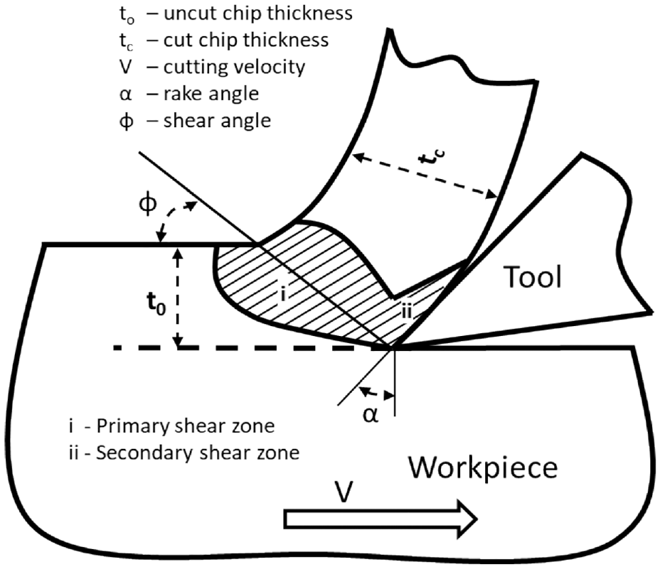
A schematic of an orthogonal plane-strain machining process.
In this work, the modified ZA model proposed from our previous study 15 is implemented as a constitutive relation for the FE simulation of orthogonal machining of AISI 1045 steel. Although several works have been reported on the FE modeling of orthogonal cutting of AISI 1045 steel using JC model, 28 there are none using the proposed ZA model whose efficacy has been reported for Inconel 718.15,26 Moreover, the proposed ZA model is based on the physics of dislocation mechanics, with the JC model being predominantly empirical. Hence, this would shed light on the actual physics underlying the deformation process. The constitutive data for the calibration of modified ZA relation for AISI 1045 steel is generated from the machining tests available in literature using the distributed primary zone deformation (DPZD) model as in our previous study. 15 The DPZD model helps in generating the constants in consonance with machining conditions with lesser number of cutting tests. In this effort, the effectiveness of the modified ZA relation for AISI 1045 steel is demonstrated by comparing the flow stress predictions with those made by the DPZD model and also by comparison of actual measurements available in literature with cutting force and chip morphology predictions of FE analysis based on the modified ZA law. Furthermore, the flow stress and cutting force predictions made using the modified ZA model were also compared with those from the original-ZA and JC constitutive relations.
Constitutive model
The FE method is a powerful numerical technique that is suitable for modeling the complex mechanics underlying metal cutting processes. However, accuracy of FE predictions is contingent on a robust material constitutive equation that accurately describes material behavior under conditions existing during the metal cutting process.
Zerilli–Armstrong model
Zerilli and Armstrong 18 have proposed constitutive models, based on the concept of dislocation mechanics, for describing the behavior of materials with face centered cubic (FCC), body centered cubic (BCC), and hexagonal close packed (HCP) structures. It should be noted that thermal activation assists the dislocations in moving past barriers in addition to the energy provided by the applied stress field during plastic deformation due to slip. 29 In particular, the movement of dislocations during plastic deformation by slip is obstructed by two types of barriers, which are long-range and short-range in nature. The long-range obstacles are those requiring higher stress values, and thermal energy may not be sufficient to go past these barriers. However, thermal energy would be sufficient to drive the dislocations past the short-range obstacles. Accordingly, the constitutive relations for different crystal-structures developed by Zerilli and Armstrong 18 are based on such dislocation-mechanics where the flow stress of a material is divided into equivalent thermal and athermal parts.26,29
Therefore, the ZA constitutive relation for FCC materials is given by,

where σ,
In this regard, Samantaray et al. 30 modified the ZA model of equation (1) in order to describe flow-behavior at elevated temperatures. The ZA model proposed by Samantaray et al. 30 is given by,
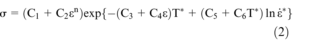


where C1 represents the yield stress; C2 and n describe strain hardening; C3 captures the absolute effect of temperature; C4 is related to the coupled effect of strain and temperature; C5 incorporates the absolute effect of strain rate; and C6 includes coupled effect of temperature and strain rate. Tr and
Modified constitutive relation
A new constitutive relation was accordingly formulated in our previous study. 15 This relation extended the modified ZA model of equation (2) through inclusion of the athermal stress component as given by equation (5). This modification was undertaken to simulate flow behavior during cutting of FCC materials for a wide range of strains, strain rates, and temperatures, while also accounting for thermo-mechanical coupling. In doing so, the proposed constitutive relation overcomes the inadequacies of popular constitutive models such as JC and ZA and facilitates effective simulation of SPD processes. 26 Accordingly, a single constitutive law was calibrated and validated for two distinct deformation mechanisms, that is, continuous-shear and shear-localization, occurring during a SPD process called metal cutting for Inconel 718. 26
Here, the constant C0 represents the athermal component, which is equivalent to the initial yield stress for FCC materials 18 and the remaining parameters are the same as in equation (2).
Calibration of the modified ZA model for AISI 1045 steel
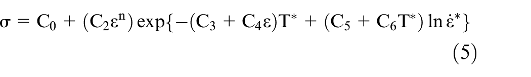
In the current study, the modified ZA model of equation (5) is calibrated for AISI 1045 steel using the analytical formulation called distributed primary zone deformation (DPZD) model, whose details have been reported in our previous effort. 15 The DPZD model proposed by Shi 31 is based on the parallel-sided shear zone theory of Oxley, 32 which is shown in Figure 2, where t0 and tc are the undeformed and deformed chip-thickness, respectively; α is the rake angle; φ is the shear angle; V represents cutting velocity; CD and EF are the entry and exit boundaries of the shear zone, respectively; and AB is the shear plane. The DPZD model generates constitutive data in consonance with the strains, strain rates, and temperatures observed during machining using various analytical formulations outlined in the effort by Shi. 31 The stress, strain, strain rate, and temperature formulations in the DPZD model were derived based on their distribution pattern in the primary shear zone by using the theories of both Merchant 27 and Oxley. 32 The primary shear zone thickness “h” shown in Figure 2 was derived from normal force component on the shear plane AB by assuming that the shear stress varies only along x direction in the primary shear zone. 31 The machining of AISI 1045 steel entails continuous chip formation at low cutting speeds while shear localized or serrated chips are generated at higher speeds. 33 Since the DPZD model can be utilized only for continuous chip formation, orthogonal cutting conditions corresponding to this mode of deformation and its accompanying experimental measurements as reported by Ivester et al. 2 and shown in Table 1 are utilized for generation of constitutive data. Ivester et al. 2 conducted orthogonal turning experiments on AISI 1045 steel tubes for varied cutting speeds, feeds, and tool-rake angles of 5° and −7° with the cutting tool made of uncoated tungsten carbide/cobalt (WC/Co) (insert grade, Kennametal K68). They measured forces, shown in Table 1, using a Kistler 9257B dynamometer, which were utilized in this study for the purpose of both calibration and validation.
Parallel-sided shear zone model.
Conditions and measurements for orthogonal cutting of AISI 1045 steel. 2
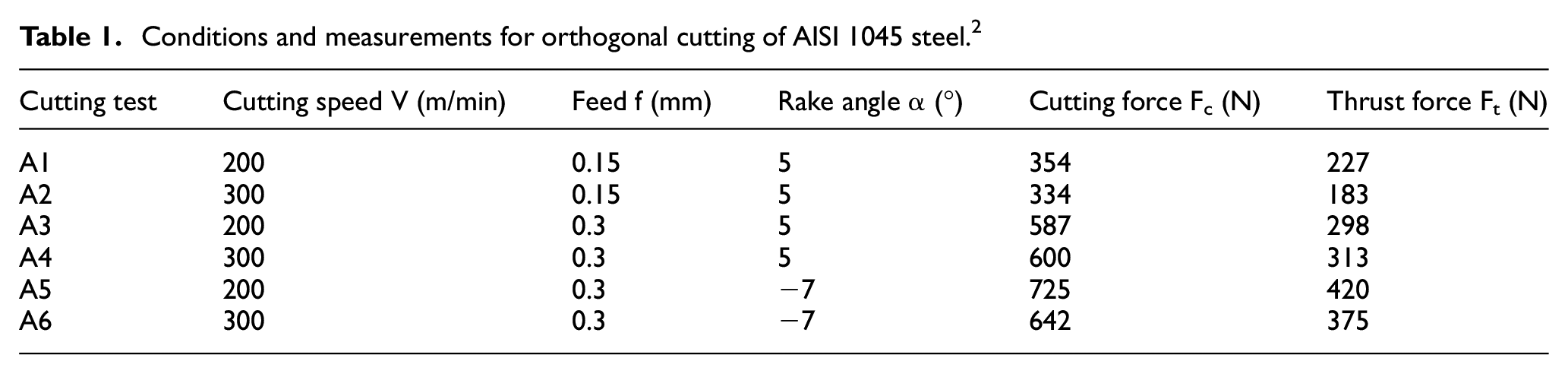
The DPZD model utilizes cutting and thrust force values along with their respective cutting conditions for generating the constitutive data. Accordingly, the distribution of stress, strain, strain rate and temperature in the primary shear zone was predicted from DPZD, whose output is plotted in Figure 3 corresponding to cutting condition A6 of Table 1. Thus, the DPZD model can predict a range of values for stress, strain, strain rate and temperature from a single cutting test, in comparison to various other methods, which require large numbers of cutting tests to generate a wide range of constitutive data. Thus, the DPZD model minimizes the number of experiments required for generating the constants. The constitutive data shown in Figure 3 was utilized for identifying the constants through the least squares technique implemented in Matlab. The least squares equation is given by:
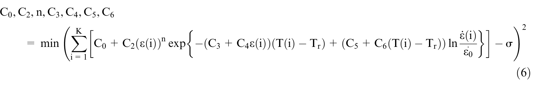
where C0, C2, C3, C4, C5, C6, and n correspond to the constants of the proposed ZA model given by equation (5), K represents the total number of datasets; and i refers to the ith dataset.
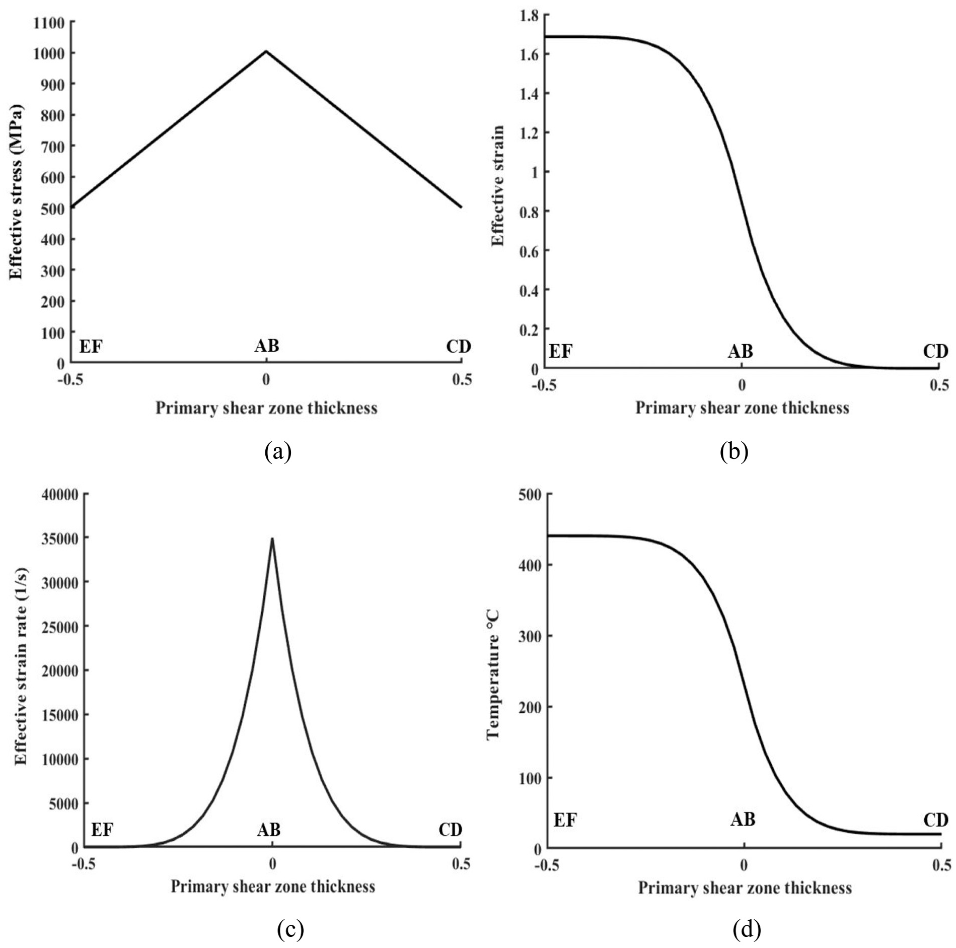
Distribution of a) stress, b) strain, c) strain rate and d) temperature in the primary zone for the cutting test A6 of Table 1.
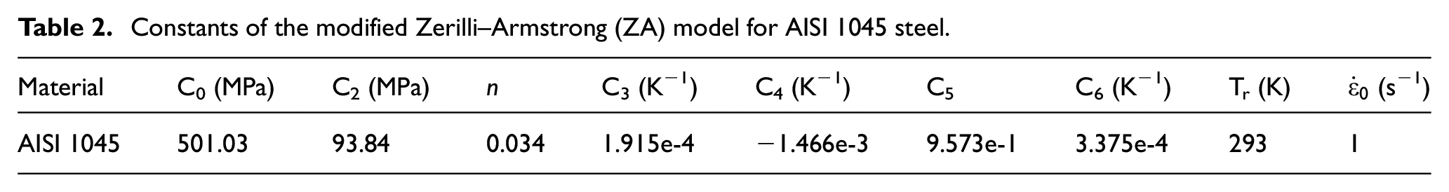
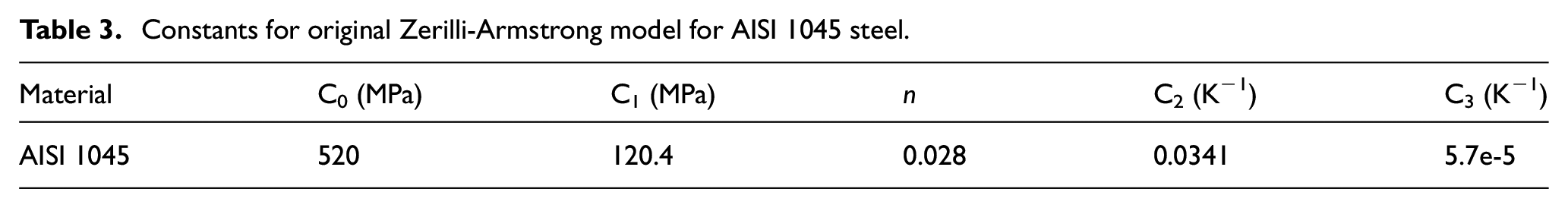
The calibrated constants for the modified ZA model for AISI 1045 steel are given in Table 2 for continuous-shear. The resulting calibrated ZA constitutive relation is implemented through a user material subroutine, VUMAT, on the Abaqus/Explicit platform. Moreover, the constants for the original ZA model of equation (1) were also calibrated for AISI 1045 steel, see Table 3, using a similar procedure so as to compare the performance of our modified ZA model with respect to the original ZA relation.
Constants of the modified Zerilli–Armstrong (ZA) model for AISI 1045 steel.
Constants for original Zerilli-Armstrong model for AISI 1045 steel.
Evaluation of flow stress prediction in the primary shear zone
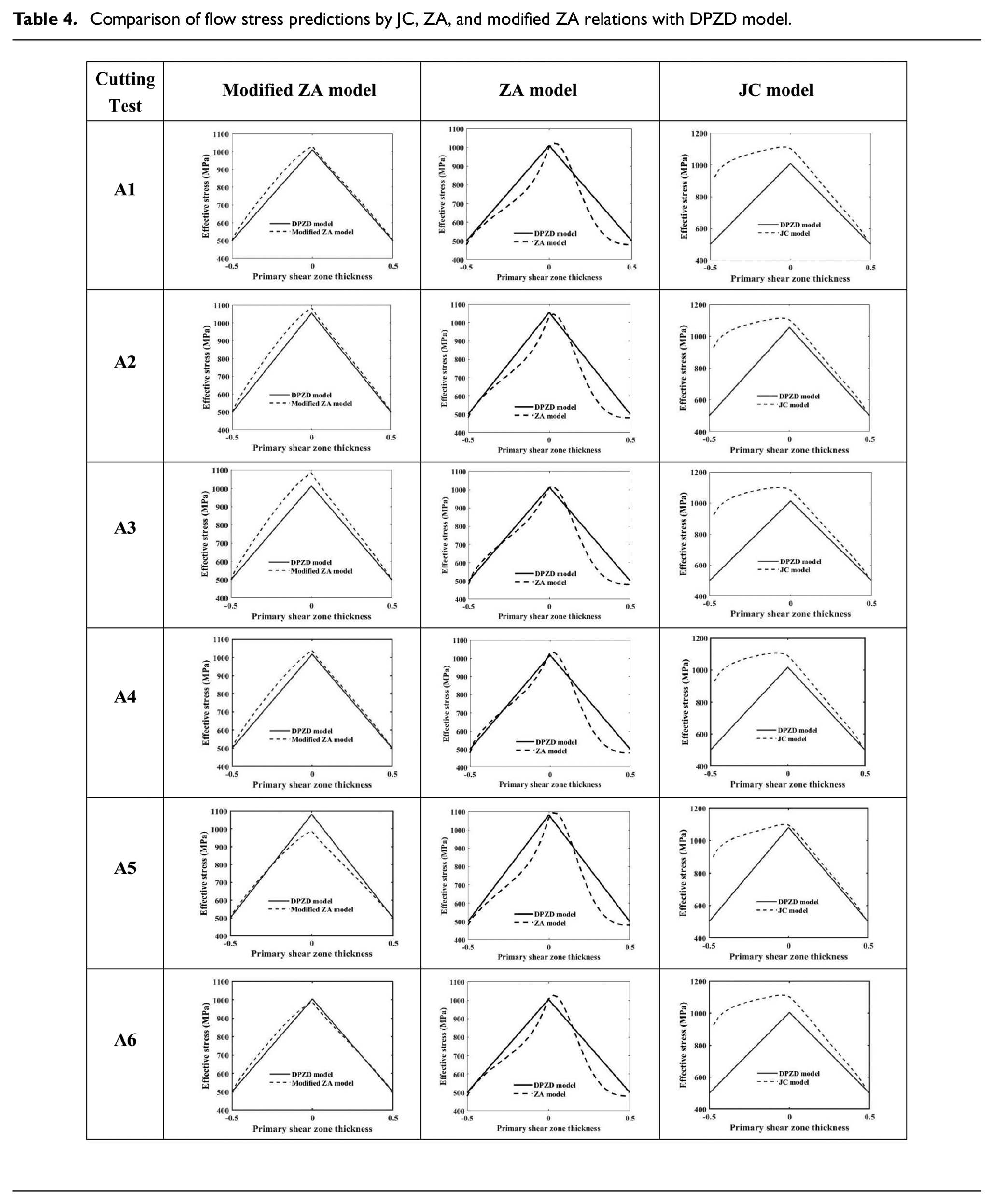
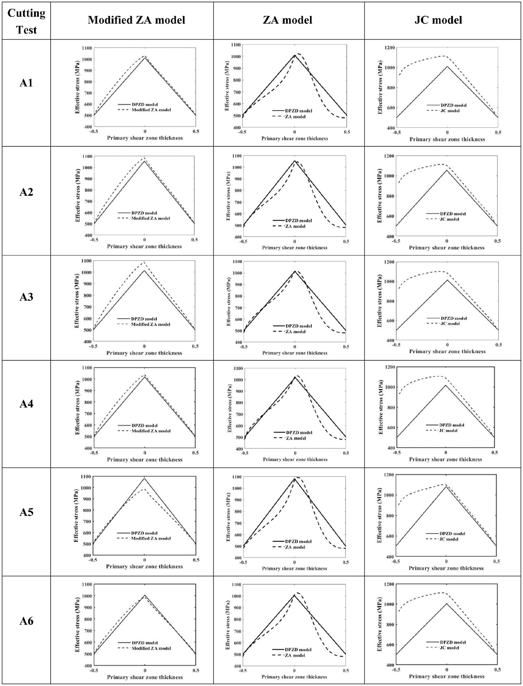
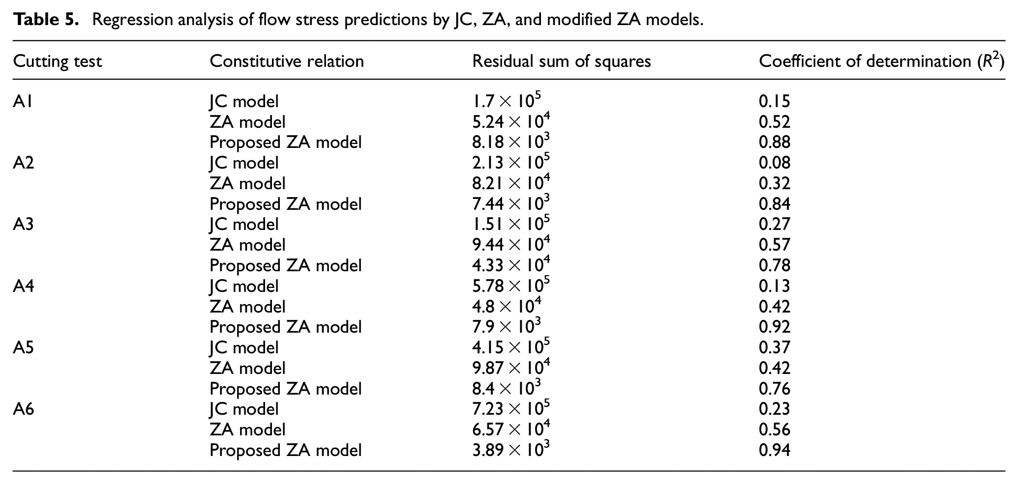
The ability of the modified ZA model to predict flow stress distributions in the primary shear zone is validated for all the cutting tests of Table 1 by comparing its predictions with those obtained using the DPZD model shown in Table 4. Similar comparisons are also made for the ZA and JC models as shown in Table 4. The flow stress values were calculated for the ZA model of equation (1) by utilizing the calibrated constants given in Table 3 and for JC model the constants reported by Ding and Shin 28 were utilized. The comparisons, as shown in Table 4, show that the modified ZA model is able to accurately predict the qualitative trend of the flow stress distribution for all the cutting tests. In contrast, the ZA and JC models performed poorly with their predicted trends being different to those generated by the DPZD model. Furthermore, the regression analysis summarized in Table 5 shows that the flow stress distributions predicted by modified ZA model have a better fit with minimum residual sum of squares (RSS) and maximum R2 value compared to the ZA and JC models for all the cutting tests. This evaluation provides evidence for the effectiveness of the modified ZA relation compared to the original ZA and JC laws in modeling the behavior of AISI 1045 steel.
Comparison of flow stress predictions by JC, ZA, and modified ZA relations with DPZD model.
Regression analysis of flow stress predictions by JC, ZA, and modified ZA models.
Finite element simulation of orthogonal machining
The modified ZA relation calibrated for AISI 1045 steel is further validated through FE simulation of orthogonal machining for cutting tests A1–A6 listed in Table 1. The accuracy of the material behavior described by the modified constitutive relation was evaluated by comparing the predicted cutting- and thrust-force values with the corresponding experimental values and also with predictions made using original ZA and JC models. Additionally, the predicted effective strain values were examined to study the physics of deformation occurring during the machining process.
Geometric description of coupled Eulerian–Lagrangian FE model
The coupled Eulerian–Lagrangian (CEL) method of FE modeling is more suitable for simulating steady state cutting involving continuous chip formation, and it possess various advantages compared to other methods whose details have been reported in our previous works.15,26 Hence, as shown in Figure 4, the CEL modeling approach is followed in this effort to model the orthogonal machining process. The CEL model involves both Eulerian and Lagrangian boundaries, and has a predefined chip geometry, which evolves gradually until reaching a steady state. The CEL does not need any chip separation criteria, and it also requires less computational time than other modeling approaches.
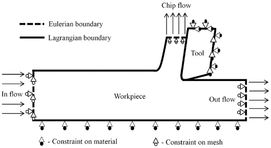
Geometric layout of coupled Eulerian–Lagrangian (CEL) finite element model.
Input and frictional conditions
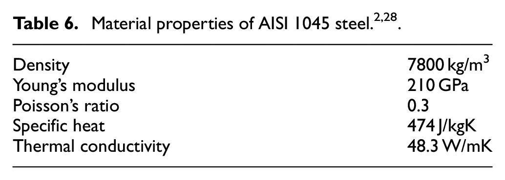
The FE simulations were conducted for a variety of orthogonal cutting conditions shown in Table 1, and the material properties, shown in Table 6, were assigned to the AISI 1045 steel workpiece. The cutting tool is held rigid, while the workpiece moves in the horizontal direction with a certain cutting velocity. The boundary conditions for the FE model are shown in Figure 4 where the Eulerian boundaries are defined for the inlet, outlet, and chip flow regions and the Lagrangian boundaries being defined for the upper and lower surfaces of the workpiece. In Figure 4, the Eulerian boundary is specified as constraint on mesh whose motion is untied to the material, and the Lagrangian boundary is specified as a constraint on material whose mesh motion is attached to the material. The mesh density affects the FE predictions of chip morphology and cutting force values34,35 and hence mesh sensitivity study was conducted by comparing the cutting force and chip morphology predictions, for different mesh densities, with experimental results. Accordingly, a graded meshing strategy as shown in Figure 5 is adopted for the workpiece with a finer mesh in the primary shear zone around the tool tip which is subjected to severe deformation and a coarser mesh away from the tool tip close to the edges of the workpiece where there is little or no deformation. An optimal mesh was found with minimum and maximum sizes of the four-node quadrilateral plane-strain element, CPE4RT, being 10 and 200 µm, respectively, through several trial simulations. The cutting tool was discretized using rigid body elements with a constant size of 10 µm as shown in Figure 5. The cutting edge of the tool was modeled with a radius of 0.02 mm corresponding to typical real time cutting-edge radii. 28
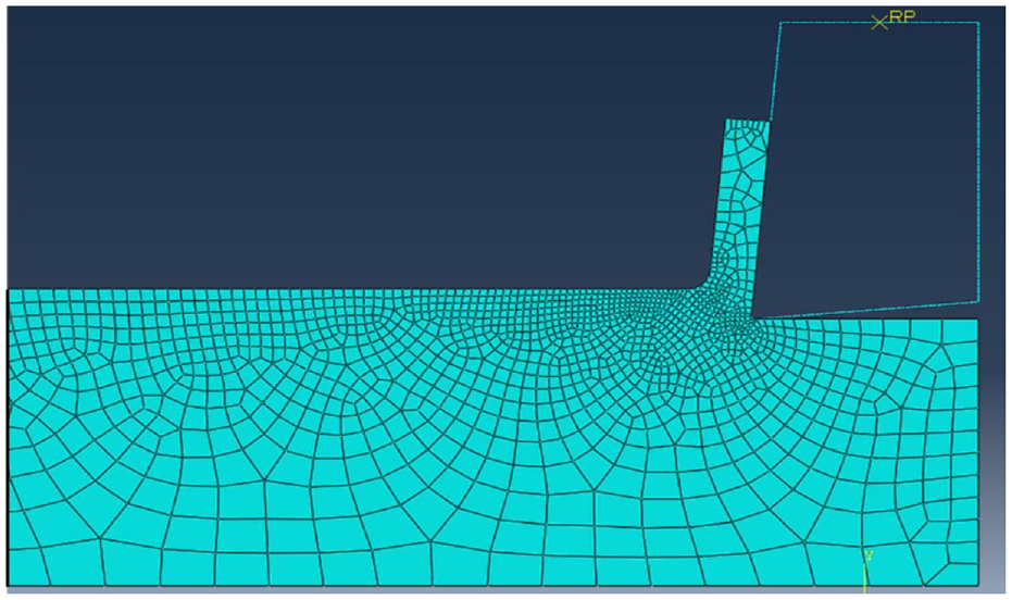
Mesh for the coupled Eulerian–Lagrangian finite element model.
The modeling of tool-chip interfacial friction has a significant influence on chip formation, and it affects the accuracy of the FE predictions. The tool–chip interface exhibits complex sticking-sliding behavior in real time, 27 but this study utilizes the Coulomb friction model for interfacial frictional conditions since the type of friction formulation has minimal effect on FE predictions made using the CEL model. 36 Several trial simulations were conducted, and a friction coefficient (µ) of 0.5 was chosen to conduct the simulations since the cutting force predictions matched well with experimental results with a maximum error of 5%.
Results and discussion
The FE results were validated by comparing predictions of cutting and thrust forces and chip morphology, including chip thickness with experimental results. The cutting force data is more sensitive to the constitutive relation utilized for describing the material behavior and, hence the predicted cutting force values were compared with experimental measurements for validation. 37 The orthogonal cutting conditions listed in Table 1 correspond to continuous chip morphology. The FE simulations conducted for these conditions using the proposed ZA model is shown in Figure 6.
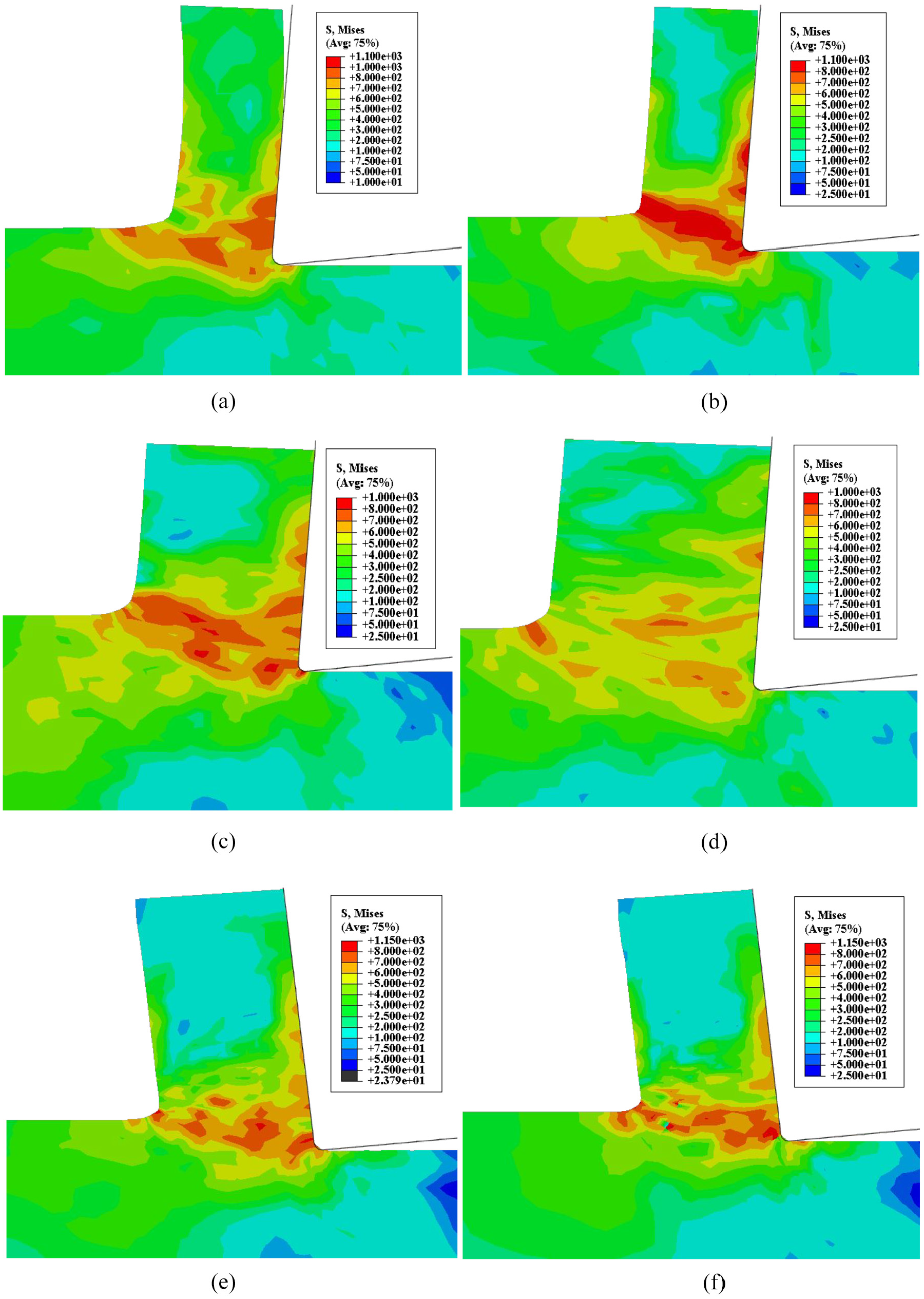
Finite element predictions, using modified ZA model, of chip morphology and von Mises stress (MPa) distribution for tests A1–A6: (a) A1, (b) A2, (c) A3, (d) A4, (e) A5, and (f) A6.
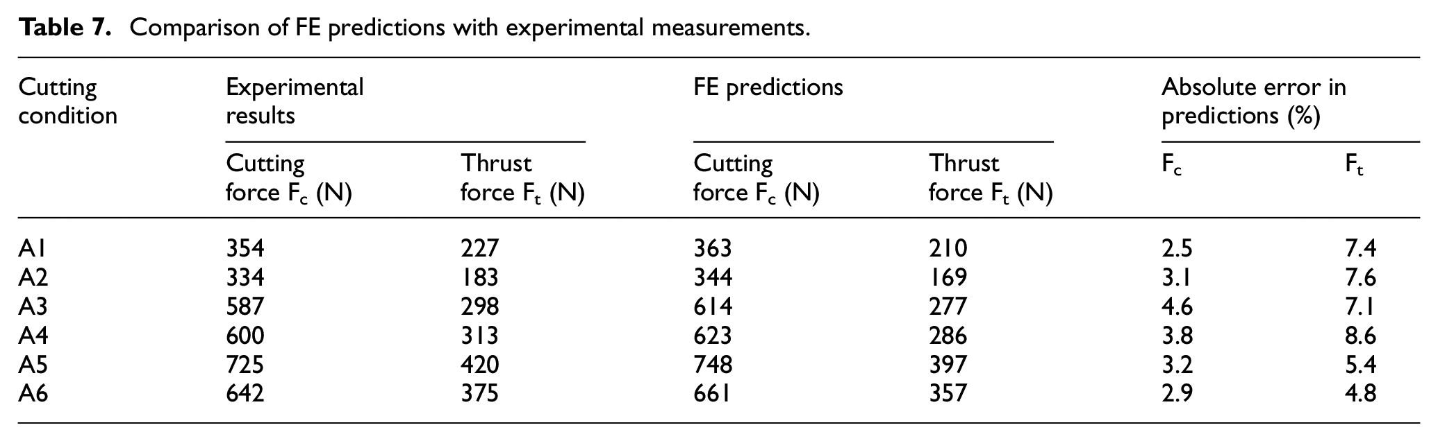
Additionally, as shown in Table 7, the cutting and thrust force predictions agreed well with the experimental results with a cumulative maximum error of 8%. It can also be observed in the entries of Table 7 that as the cutting speed increases, the cutting forces decrease, and the FE predictions made using the modified ZA relation capture this trend successfully. Accordingly, Figure 7 shows that the predicted trend of cutting force agrees well with the experimental values.
Comparison of FE predictions with experimental measurements.
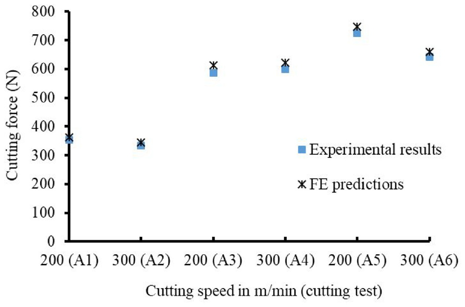
Comparison of experimental and predicted trend of cutting force values.
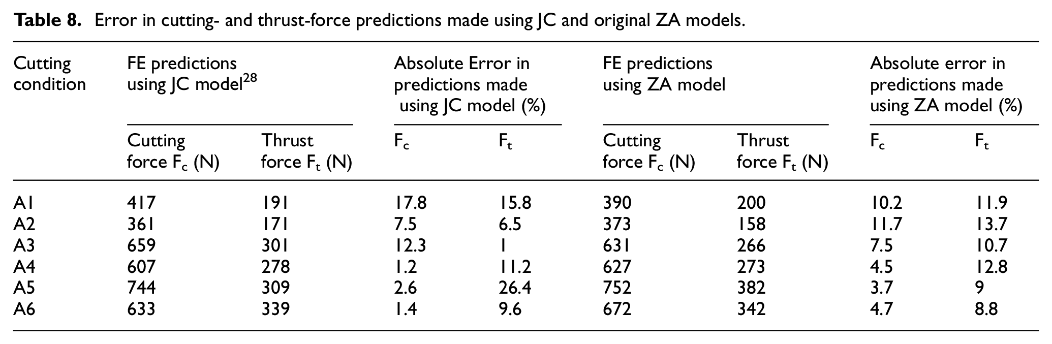
The simulations were also conducted for the original ZA relation of equation (1) whose predictions of both chip morphology and Mises stress distribution for cutting tests A1–A6 are shown in Figure 8. Other than predicting a continuous chip morphology, Table 8 lists cutting and thrust force values forecasted by the original ZA relation that had maximum errors of 12% and 14% respectively compared to experimental values. These error values were higher than those predicted using the proposed ZA model but lower than the JC relation as represented in Figures 9 and 10.
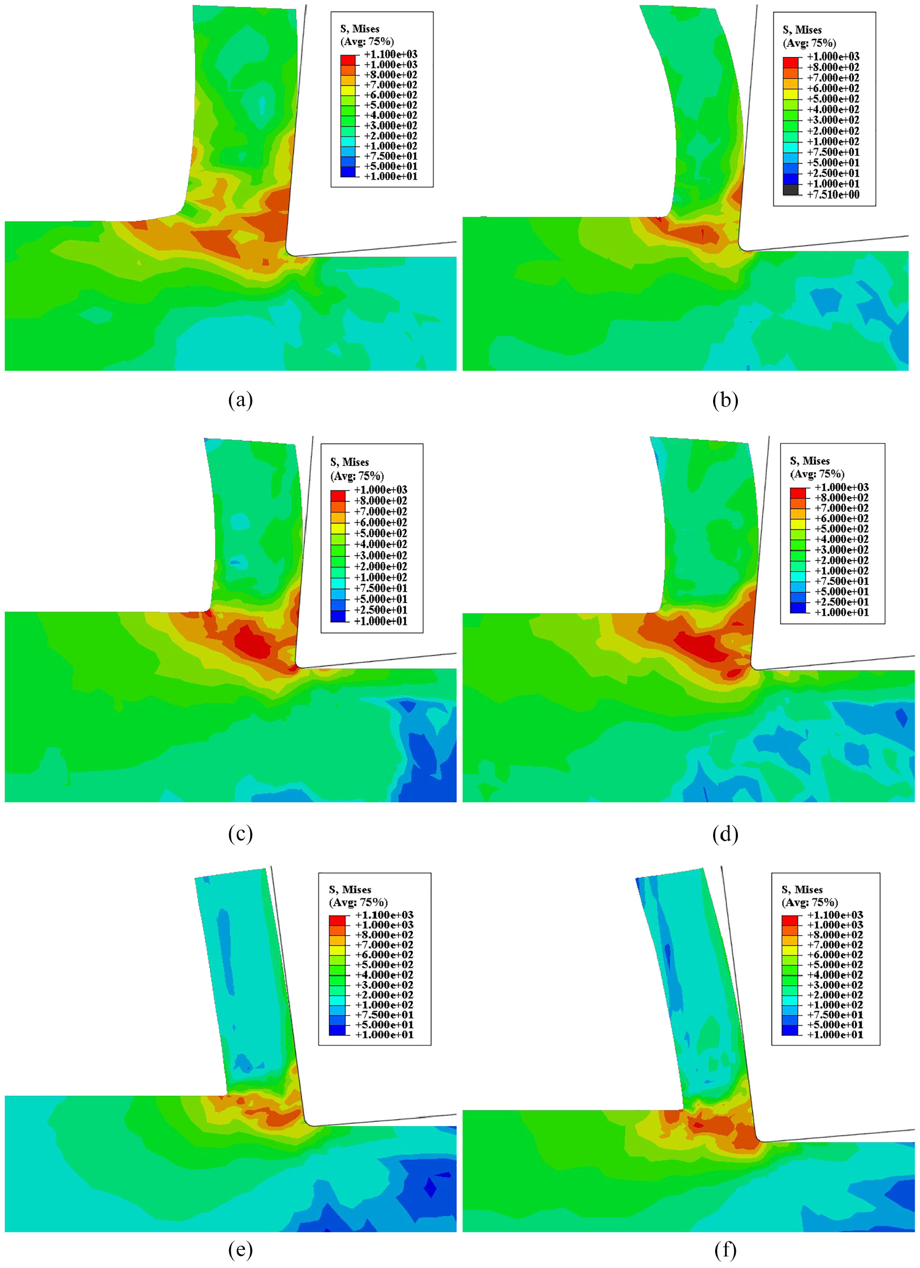
Finite element predictions of chip morphology and von Mises stress (MPa) distribution for tests A1–A6 by original ZA model: (a) A1, (b) A2, (c) A3, (d) A4, (e) A5, and (f) A6.
Error in cutting- and thrust-force predictions made using JC and original ZA models.
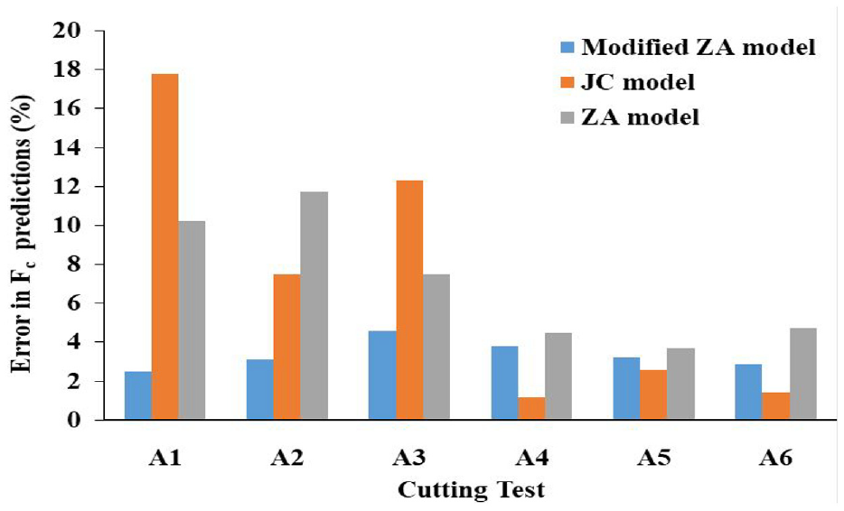
Comparison of errors in cutting force predictions between modified ZA, JC, and original ZA models.
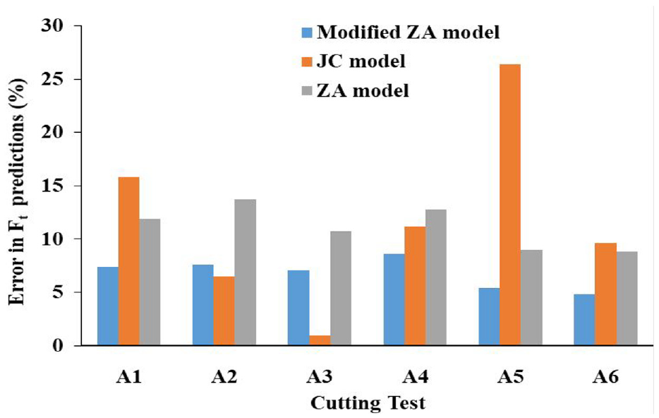
Comparison of errors in thrust force predictions between modified ZA, JC, and original ZA models.
Ding and Shin 28 conducted orthogonal cutting simulations of AISI 1045 steel using the JC model and their cutting and thrust force predictions for the cutting tests A1–A6 are shown in Table 8 along with errors when compared to experiment values. Moreover, comparison of errors in force predictions with the modified ZA, JC, and original ZA models are presented in Figures 9 and 10. Ding and Shin 28 reported maximum errors of 18% and 26% in cutting- and thrust-force predictions respectively using JC model for the cutting conditions listed in Table 1. These are higher than the predictions made using our modified ZA model with its maximum errors of 5% and 8%, see Figures 9 and 10. Hence, prediction accuracy for cutting and thrust forces were also better for the modified ZA relation than those using original ZA and JC relations. Thus, FE-based validation confirms the effectiveness of the modified ZA relation in simulating the deformation behavior of AISI 1045 steel during severe plastic deformation processes such as machining.
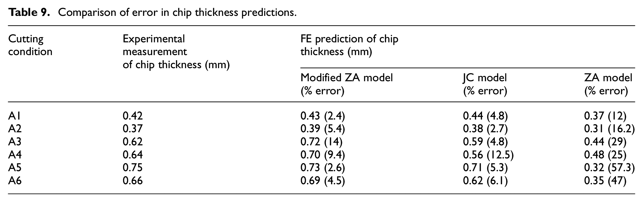
The comparison of error in chip thickness predictions made using the modified ZA, JC and original ZA models are summarized in Table 9. The chip thickness is overestimated for few of the cutting tests due to Eulerian chip boundaries as reported by Arrazola and Özel. 38 The chip thickness predictions made using the modified ZA and JC models had a maximum percentage-error of 14 and 12.5 respectively. But the predictions made using the original ZA model had a maximum error percentage of 57 which is far higher than the predictions by both modified ZA and JC relations. Thus both modified ZA and JC relations performed comparatively better than the ZA model in predicting the chip thickness values.
Comparison of error in chip thickness predictions.
The FE predictions of effective strain values for cutting tests A1–A6 are shown in Figure 11. The predicted trend of effective strain shown in Figure 3 exhibits a maximum value of strain along the shear plane, and strain gradient reaches zero as the chip moves past the shear zone. Accordingly, the FE predicted strain values confirm the trend of Figure 3, except for higher strains along a smaller fraction of the chip thickness near the tool-chip interface due to friction. Negative rake angles impose higher strain when compared to positive rakes for constancy in cutting speed and depth of cut values. 27 The FE prediction of effective strain shown in Figure 11 was able to capture this effect of rake angle and the imposed strain is higher for cutting tests A5 and A6 corresponding to a negative-rake tool when compared to A1 and A2 for positive rake. This intense straining of the material in the deformation zones is also evident in the higher cutting forces recorded and also predicted by the modified ZA relation-based FE model, see Table 7. In fact, the stress distributions of Figure 6 also show intense deformation when cutting with negative rake tools. Thus, the FE simulations conducted using the modified ZA model were able to capture the actual deformation characteristics observed during the machining process.
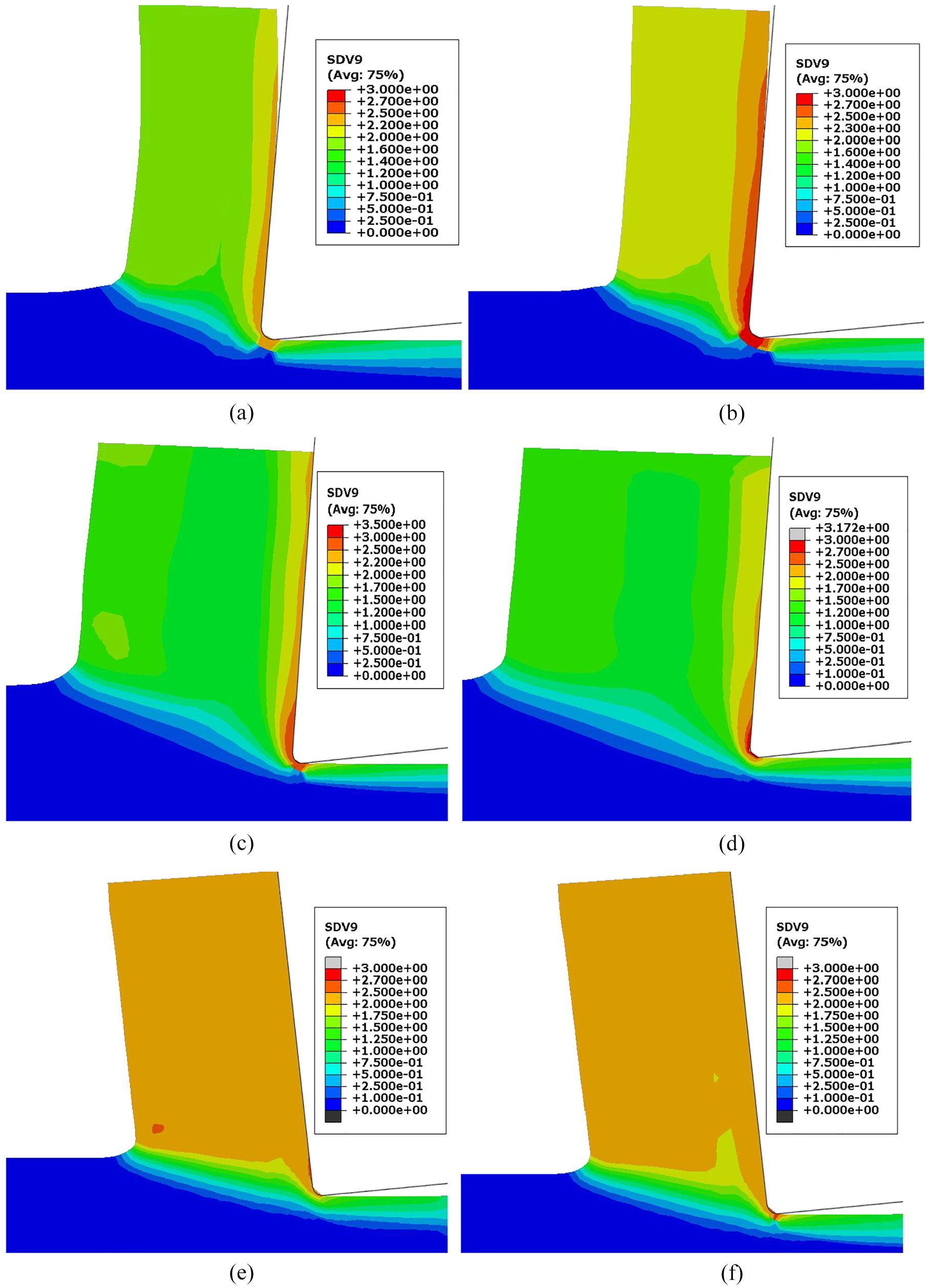
FE prediction of effective strain for cutting tests A1–A6: (a) A1, (b) A2, (c) A3, (d) A4, (e) A5, and (f) A6.
Overall, validations carried out in this paper have proved the effectiveness of the modified ZA model in describing the behavior of AISI 1045 steel alloy, an FCC material, during the simulation of machining process. Hence, the results and validations of this paper together with our earlier investigations15,26 have demonstrated the effectiveness of the modified ZA relation in capturing deformation behavior of FCC materials. Consequently, the modified ZA law can be utilized for simulation and hence effective design of other severe plastic deformation processes involving FCC materials. Moreover, the extension of the modified ZA relation to other crystal structures will pave the way to the successful design of three-dimensional-oblique operations such as milling, drilling, and grinding which involve severe plastic deformation in a very small deformation zone. Simulation in manufacturing using accurate constitutive relations for designing processes without experimentation is crucial to sustainable development. Such simulations are warranted when constraints on resource consumption are crucial for positively influencing the environment.
Conclusions
The proposed modified Zerilli–Armstrong relation was validated through flow stresses computed in the deformation zone and also finite element analysis of the machining of AISI 1045 steel under orthogonal and plain-strain conditions. The material parameters were identified using constitutive data generated using the analytical formulation called distributed primary zone deformation model. The flow stress distributions predicted by the modified Zerilli-Armstrong relation agreed well with the flow stress data generated using the distributed primary zone deformation model with better statistical results suggesting that it provides a better fit compared to the original Zerilli-Armstrong and Johnson-Cook models. The performance of the constitutive law in simulating plane-strain orthogonal cutting of AISI 1045 steel was also evaluated by investigating the accuracy of cutting and thrust forces predicted by the finite element model based on the coupled Eulerian–Lagrangian approach. The predictions of cutting forces had a maximum error of 5% over a wide range of cutting conditions compared to the experimental values. The predicted effective strain values also match the trend generated using distributed primary zone deformation model while also providing information regarding the nature of deformation during the machining process. Moreover, the proposed Zerilli-Armstrong relation has successfully simulated severe plastic deformation for positive and negative rake angles of tool and, hence a wide range of strains corresponding to variations in geometry of deformation-zone. The force predictions made using the modified ZA relation also had less error for most of the cutting tests when compared to those predicted using the original Zerilli-Armstrong and Johnson-Cook laws. Further both the modified Zerilli-Armstrong and Johnson-Cook relations performed well in predicting chip thickness values for all the validated cutting tests compared to the original Zerlli-Armstrong model. The successful validations reported for the orthogonal plane-strain machining of AISI 1045 steel provide further evidence of the accuracy of the modified Zerilli–Armstrong constitutive relation in simulating severe plastic deformation processes of face centered cubic materials.
Footnotes
Declaration of conflicting interests
The author(s) declared no potential conflicts of interest with respect to the research, authorship, and/or publication of this article.
Funding
The author(s) received no financial support for the research, authorship, and/or publication of this article.