
Abstract
Dead metal cap plays an important role in the microcutting process because target material piled up on the tool–chip–workpiece interface can alter the cutting geometry. The target of this study is to model and simulate the micro-orthogonal cutting process in the presence of dead metal cap in order to investigate the effects of this phenomenon on the micromachining process outputs (cutting force, thrust force and chip thickness) and stress distribution, equivalent plastic strain and temperature inside the workpiece shear zones. For this purpose, the finite element method with explicit dynamic solution and adiabatic heating effect along with arbitrary Lagrangian–Eulerian approach is used. It is shown that the finite element models with current state-of-the-art assumptions cannot take into account the dead metal cap by default. For this reason, dead metal cap is artificially introduced on the rounded tool edge in this study for carrying out a proper analysis. Several simulations with different dead metal cap geometries are performed and obtained results show that prediction of cutting force, thrust force and chip thickness are sensitive to the presence of dead metal cap and its geometry. Micro-orthogonal cutting experiments are carried out on tubular AISI 1045 workpieces for validating and interpreting simulated results. The error between predicted and experimental data is calculated, and it is shown that simulation performances can be improved by considering the dead metal cap into the process model. For example, it is possible to reduce the error to less than 5% in case of thrust force prediction. This study points out how the target material’s Von Mises stress, equivalent plastic strain and temperature distribution are sensitive to any alteration of the edge geometry due to the dead metal cap. The best dead metal cap configuration in terms of agreement with experiments is also the one introducing a more homogeneous distribution of these quantities along the shear plane.
Introduction
The demand for production of very small parts and features is increasing, and micromachining is one of the most frequently used processes for manufacturing three-dimensional (3D) miniaturized products because of its applicability to a wide range of materials, its flexibility and moderate cost. 1 For example, micromachining allows to create products for the biomedical and the aerospace sectors, micromolds for the microinjection process and small-size high-tech parts for the electronics sector.
Besides the broad application of this manufacturing process, its basic phenomena still need to be fully understood, thus making the machining modeling in the microscale more complex than in the macroscale. The complete determination of these phenomena would provide two important advantages: (1) a better modeling of tool–workpiece interaction, which leads to the prediction of the machine tool behavior and, as a result, a better design and manufacturing of machine components; and (2) a better prediction of the cutting process final output, which helps the end users to design the machining operations for the target product.
Going into further details, the modeling of machining operations in the macroscale has to face the complexity associated with the target material’s flow stress and contact behavior. In addition, the size effect adds more complexity to the process modeling in the microscale, representing a challenge for accurate predictions. In fact, when the uncut chip thickness is comparable in size to the critical tool geometrical features, as the cutting edge radius, the effective rake angle2,3 gains an important role in the chip formation, the plowing action becomes more relevant than the shearing action and the specific energy consumption for the material removal changes non-linearly with the uncut chip thickness reduction. 4 In addition, the material microstructure increases its effectiveness on cutting forces, since the critical tool geometrical features tend to have the same magnitude order of the material grains. 4 Micromachining is also affected by the minimum uncut chip thickness (MUCT) effect, 5 meaning that the chip does not form when the uncut chip thickness is below a critical value and plowing takes place instead of shearing.
Figure 1 indicates two possible models of the material flow in front of the tool cutting edge. In Figure 1(a), the material flow separates at the tool cutting edge in front of the stagnation point S. Figure 1(b) introduces the dead metal cap (DMC) that is an amount of piled up material stuck around the tool cutting edge. DMC is similar to built-up edge (BUE) but is stable (in fact, in some research works it is referred as stable BUE6,7) and its existence does not depend on the cutting velocity. 8 With the presence of DMC (Figure 1(b)), flow zone and stagnation point move away from the tool cutting edge, this way modifying the whole microcutting geometry and leading to unexpected process behaviors in terms of chip formation and force magnitude.
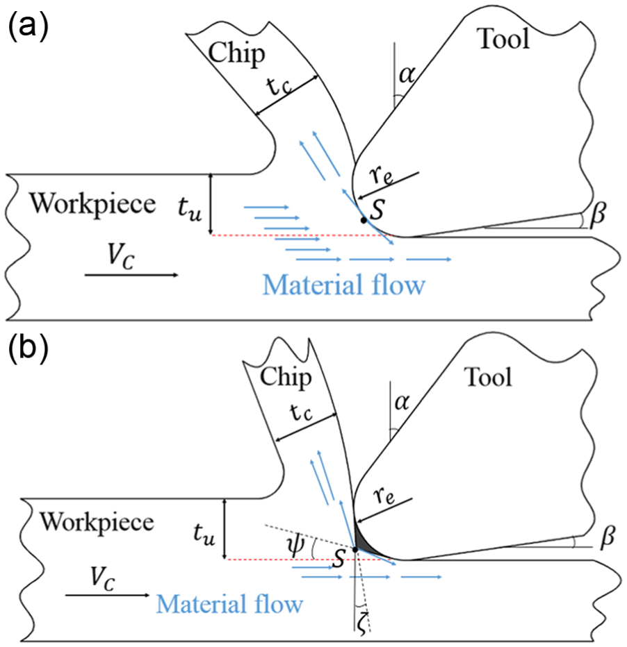
Material flow in microcutting: (a) stagnation point (S) on tool edge radius and (b) stagnation point (S) on dead metal cap (DMC).
Providing experimental evidence of the DMC presence is a challenging task due to the phenomenon scale, but there are some research works proving the DMC existence.6,9,10 For instance, Abdelmoneim and Scrutton 6 performed quick-stop experiments on free-cutting brass (CuZn36Pb3) and noticed a stable BUE. Warnecke 9 was one of the first researchers who observed the cutting process by means of a high-speed camera for different cutting velocity ranges and proved that DMC exists for AISI 1045 steel. The study of Kountanya and Endres 10 was based on high magnification visualization of the cutting process and confirmed the presence of piled up material in front of tool edge for cartridge brass (CuZn30), but not for commercially pure zinc.
Throughout the literature, DMC has been investigated by means of experimental works and analytical or numerical models. Jacobson and colleagues11–13 performed an experimental investigation of the DMC effect on the intermittent cutting of plain carbon steel (AISI 1045) and austenitic stainless steel (AISI 316) and proposed a classification of dead zones in the cutting process. Furthermore, Abdelmoneim and Scrutton 6 obtained upper-bound solutions to a theoretical analysis of the metal cutting process with stable BUE created in machining of free-cutting brass (CuZn36Pb3) and found an agreement between theoretical analysis and experimental data.
Analytical models and, in particular, slip-line field models are widely used since they are easier to implement and require a lower computational time than numerical models. 14 For example, Waldorf et al. 7 proposed a slip-line field model for studying the case of rounded tool edge in the presence of DMC and were able to predict both plowing and shearing forces in orthogonal cutting of 6061-T6 aluminum. Waldorf et al. 15 performed a comparison between two slip-line field solutions (with and without DMC) for machining 6061-T6 aluminum and found that the model considering DMC could provide a better estimation of experimental results. In other papers, Karpat and Özel 16 used a slip-line field model including DMC to study the mechanics and friction in orthogonal cutting of AISI 4340 steel with rounded tools while Jun et al. 17 developed a model for cutting force prediction in microend milling that is based on a slip-line field model considering DMC. Nevertheless, it should be pointed out that slip-line field models are based on the strong assumption that the target material is perfectly rigid plastic 18 and they provide unique solution for each machining problem 14 so these facts limit their prediction performance.
Finite element analysis (FEA) is another technique that plays a significant role in DMC modeling, since it can include a wide variety of material flow stress models and can directly provide information on industrially relevant outcomes (such as chip shape, burrs and surface finish). 14 For instance, some studies focused on predicting DMC formation beneath the tool cutting edge for P20 19 and AISI 1045 20 steels by representing the material plastic flow through the Johnson–Cook flow stress model, even if this assumption is against the fact that DMC is the result of a ductile shear failure since the Johnson–Cook flow stress model cannot take into account the material failure. Childs 21 performed FEA of AISI 5130 steel machining including a ductile shear failure model in order to predict the formation and geometry of BUE in macro cutting and DMC in microcutting, but he concluded that his model could not follow the evolution of these phenomena. In fact, a limitation of finite element (FE) models is that they cannot take into account the DMC basic stationary properties and represent the creation of DMC by means of simple flow stress models without implementation of material failure model.
This article presents a two-dimensional (2D) finite element simulation of AISI 1045 orthogonal cutting in the microscale where DMC is artificially introduced to consider its stationary properties and let the target material freely flow on the DMC–chip contact surface. The novelty of developed model can be summarized in the ability to perform proper micromachining simulations with the presence of DMC. AISI 1045 steel is selected as target material because of its broad application for basic academic investigations, 22 and since microcutting of this material is of interest, thanks to its potential to achieve good surface and geometry quality in micro-sized dies and molds. 1 This article investigates the effects of DMC on the process output parameters (namely, cutting and thrust forces, chip thickness and stress, strain and temperature distributions within the workpiece deformation zones) and validates the finite element method (FEM) results by comparing them with data coming from microcutting experiments.
Finite element modeling of micro-orthogonal cutting
Modeling setup definition
A 2D micro-orthogonal cutting on AISI 1045 steel is modeled. The DMC geometry is artificially introduced on the tool edge surface. Based on the experimental observations of Warnecke 9 and Kountanya and Endres, 10 the DMC is modeled with a sharp corner edge and smooth faces (Figure 1(b)). According to the theory of Jun et al., 17 the two faces of DMC are tangents to the tool edge radius to facilitate the material flow over rake and clearance faces. To make DMC fully constrained in space, it is necessary to introduce two angles, namely, rake ζ and clearance ψ angles of DMC (Figure 1(b)).
In this study, two values for both ζ and ψ angles are selected in order to investigate the effects of DMC geometry and to perform a sensitivity analysis on the FEM output variables with respect to DMC angles. Figure 2 shows the different DMC geometries on the tool edge that result from varying angle ζ and ψ. A rounded tool edge is also used in finite element simulations to allow a result comparison (section “Results and discussion”).
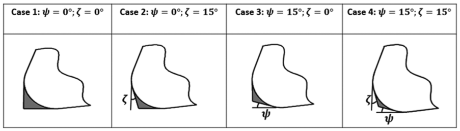
DMC geometries analyzed in this study.
The workpiece is meshed with quadrilateral continuum elements (CPE4R), 23 which enable the displacement calculation during the analysis and can take into account the adiabatic heating effect. The mesh geometry spreads uniformly throughout the workpiece and the element size is 1 µm × 2 µm. The tool and the DMC, if any, are considered as a unique completely rigid body. The workpiece is designed as a rectangle with width of 60 µm and length of 230 µm, including 7020 elements in total.
As depicted in Figure 3, the tool is totally fixed at the reference point (RP), where the simulation outputs are extracted. The workpiece is set as a moving object that is constrained along its bottom side (Line AB in Figure 3) with zero displacement in the Y direction and along its left side (Line AD in Figure 3) with zero displacement in Y direction and velocity in X direction equal to the cutting velocity.
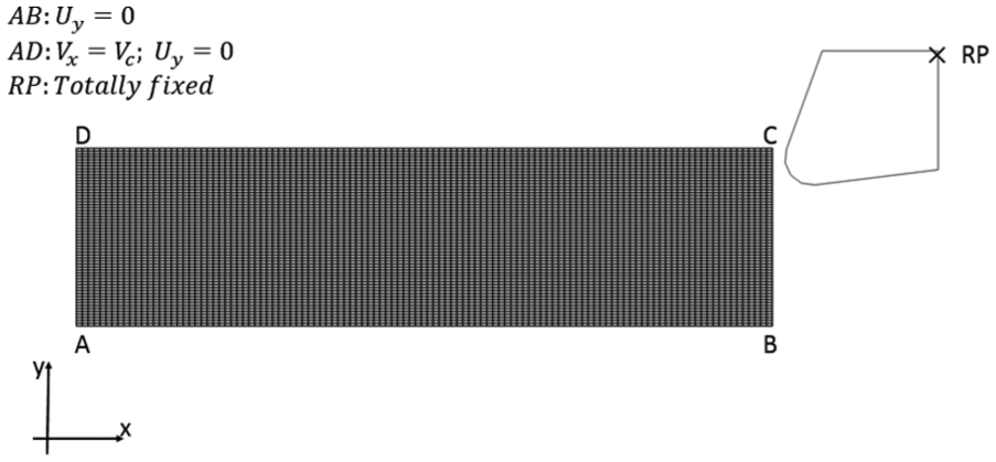
Tool–workpiece assembly with boundary specifications.
Solution method
The micro-orthogonal cutting operation is simulated by ABAQUS with explicit dynamic solution and adiabatic heating effect along with adaptive arbitrary Lagrangian–Eulerian (ALE) mesh distortion control. Indeed, explicit formulation based on central difference method 23 has been exploited in several studies24–26 for simulating high-speed machining. FEA of machining, considering the adiabatic heating effect, has been used and validated in the works of Jin and Altintas 27 and Mabrouki and Rigal. 28
In micromachining simulation, the material undergoes severe deformations, and mesh distortion is very likely to occur beneath the tool edge, but ALE technique allows to maintain a high-quality mesh in front of the tool tip. The ALE formulation is a combination of pure Lagrangian technique (where the mesh moves together with the material) and pure Eulerian technique (where the mesh is fixed in space and the material flows inside the domain). ALE method has been exploited for machining simulation in several research works.19,20,24–26,29,30 In metal cutting simulations, there are different numerical methods to avoid mesh distortion on workpiece deformation zones, namely, ALE, Eulerian, Lagrangian with remeshing-rezoning and smoothed-particle hydrodynamics (SPH). Advantages and disadvantages of each modeling technique are well described through literature.31–34 In this work, ALE approach, despite disadvantages associated with this technique such as loss of data due to the remapping of state variables, is used because of its capability to simulate machining process with lower computational effort in 2D.
In this field, the ALE approach can be implemented without a chip geometry initialization and with pure Lagrangian boundaries or, alternatively, by initializing the chip geometry and with a combination of Lagrangian and Eulerian boundaries. 35 In this study, the ALE technique is implemented without any chip geometry initialization because the chip shape is unknown when cutting with small uncut chip thickness, that is, comparable with edge radius of the tool. ALE adaptive mesh domain can be controlled by frequency and the number of remeshing sweeps per increment which are set to be 5 and 4, respectively, for all the simulations of this study, and they are based on preliminary simulation tests with goal of having proper mesh quality beneath the tool edge.
Flow stress model
The Johnson–Cook law 36 (equation (1)) is used for modeling the plastic deformation behavior of the selected target material (AISI 1045 steel). This model is formulated as follows
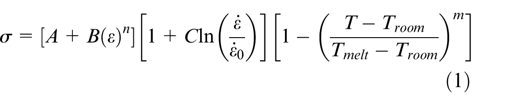
where the Johnson–Cook parameters
37
and thermo-mechanical properties
26
of the selected target material (AISI 1045) used in FE model are A: initial yield stress at room temperature = 553.1 MPa, B: strain hardening coefficient = 600.8 MPa, C: strain rate sensitivity coefficient = 0.0134, m: thermal softening exponent = 1, n: strain hardening exponent = 0.234,
Contact law
In high-speed machining and especially in cutting with low uncut chip thickness, where the tool edge radius plays a significant role on the cutting action, there are interactions within bodies with complex contact properties due to the high plastic deformation generating high stresses, strains and strain rates. The friction modeling in high-speed machining has been the subject of several studies. For instance, Haglund et al. 38 performed the finite element simulations with ALE approach and Eulerian boundaries together with different types of friction models. They concluded that using a shear stress threshold to represent the stick-slip behavior in the contact zone is an inadequate approach for force prediction in models with Eulerian boundaries. However, Arrazola and Özel 35 made a research work discussing different types of friction models in FEA of metal cutting processes. They investigated the applicability of a modified Coulomb friction model with shear stress threshold and two different ALE techniques, concluding that the shear stress limitation can affect the results and becomes effective for the model with Lagrangian boundaries.
In this study, Lagrangian boundaries are selected (section “Solution method”), hence the modified Coulomb friction model with shear stress threshold is applied to include the stick-slip behavior of the target material in contact with a rigid body, that is, the tool–DMC assembly. In this study, according to the work by Woon et al.
26
that performs the finite element simulation of AISI 1045 micromachining with an ALE approach, a constant friction coefficient equal to 0.45 is used and shear stress limit is adopted by calculating
Experimental procedure
Experimental setup
For comparing and validating the FEM results, micro-orthogonal cutting tests are performed on an ultra-precision Kern EVO 5-axis machining center with nominal positioning accuracy of ±1 µm. Tubular workpieces made of AISI 1045 Steel with a wall thickness of 0.65 mm are turned by SANDVIK standard uncoated carbide inserts (DCGX070202-AL H10). The micro-orthogonal cutting setup is shown in Figure 4.
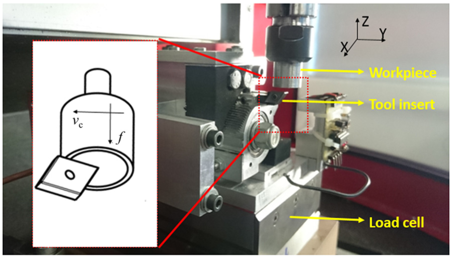
Micro-orthogonal cutting setup on a Kern EVO machining center.
The insert geometry is inspected by means of a 3D optical measuring machine (Alicona Infinite Focus) and the measured edge radius (re), rake angle (α) and clearance angle (γ) are 9 µm, 20° and 7°, respectively (Figure 5(A)). Measurements of rake and clearance angles are carried out by placing the insert bottom surface in contact with the Alicona Infinite Focus table that is used as reference.
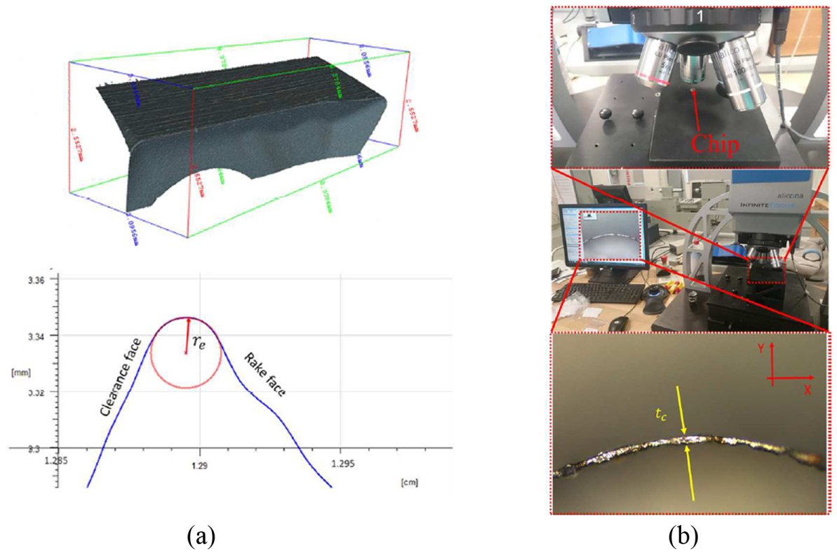
(A) Insert acquisition and (B) chip thickness measurement by Alicona Infinite Focus.
Experimental design
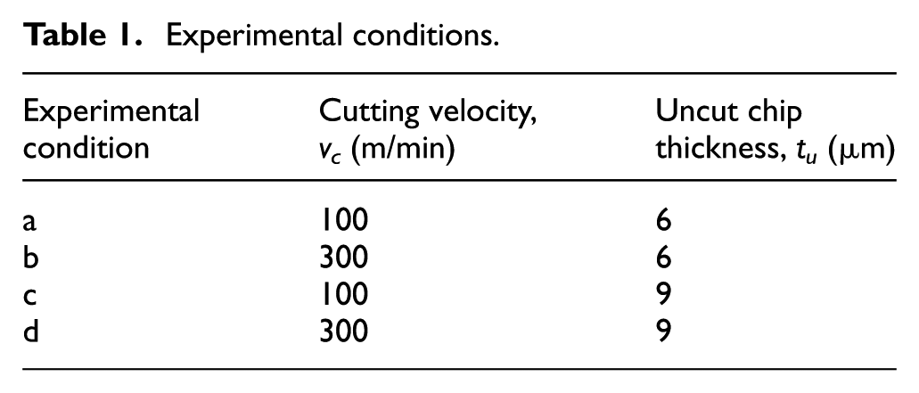
DMC is placed in front of tool edge radius, hence two uncut chip thickness values (6 and 9 µm) are selected in this study for micro-orthogonal cutting experiments in order to study the DMC effects on the process outputs when machining with an uncut chip thickness compared to the tool edge radius (re = 9 µm). Moreover, two different levels of cutting velocity (100 and 300 m/min) are also considered in this study (in order to investigate if DMC geometry is sensitive to cutting velocity changes) (Table 1). Two replicates are performed for each experimental condition, hence the experimental plan consists of eight runs. The experiments are fully randomized.
Experimental conditions.
The experimental study pointed out the willingness of the material to stick on the tool edge radius (Figure 6), this way verifying the DMC existence in microcutting of AISI 1045. Scanning electron microscopy (SEM) analyses of the tool showed that the fresh edge (Figure 6(a)) is covered by the target material after performing cutting experiments (Figure 6(b)).
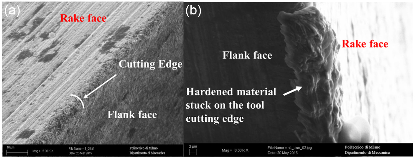
SEM images: (a) fresh tool and (b) material stuck on the tool cutting edge (re = 9 µm, tu = 6 µm and vc = 300 m/min).
Experimental responses
During each experiment, the cutting and thrust force components (respectively, the forces in X and Z directions) are acquired using a Kistler 9257BA triaxial piezoelectric load cell and the mean values of both force signals throughout the steady cutting phase are calculated.
After each cutting test, the chips are collected for offline, measuring their thickness by means of Alicona Infinite Focus, as depicted in Figure 5(B). Each chip is measured perpendicularly to its lateral surface in five different positions along its length, and the chip thickness value tc is calculated as the mean of these five measurements. Table 2 shows the experimental results for cutting force, thrust force and chip thickness.
Experimental results.
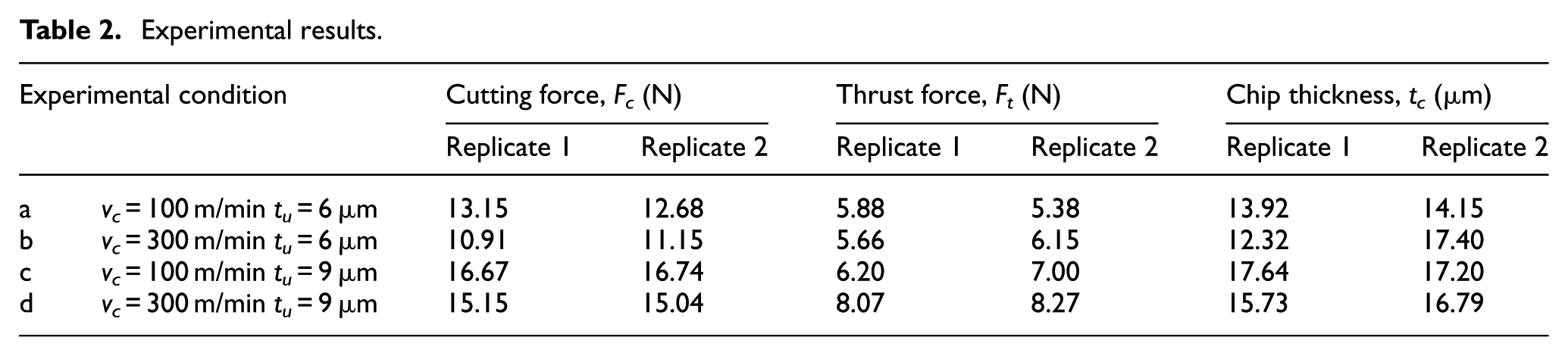
The percentage error between experimental process outputs and predicted results is calculated as follows

where the subscript i becomes “c,”“t” and “tc” when the considered process output is, respectively, the cutting force, the thrust force or the chip thickness. These errors are calculated with respect to the mean value of experimental results that are reported in Table 2.
Results and discussion
The results obtained with developed FE model implementing ALE approach and artificially introduced DMC are discussed in this section and compared with the results obtained with a rounded tool edge. FEM results are compared with experiments.
As shown in Figure 7(a), when considering a rounded tool edge, an area exists beneath the edge where the material speed is extremely low. This zone is claimed to be DMC in some studies,19,20 but here neither the total speed (Figure 7(a)) nor its components along cutting and thrust direction are uniformly equal to 0 m/s, and this fact is against the basic condition of DMC stationary nature. Figure 7(d) shows the velocity components v1 and v2 (respectively in cutting and thrust direction) for 5 nodes selected on the arbitrary line AB drawn below the tool edge radius (Figure 7(c)). For example, v1 and v2 of node 5 are 0.0519 and 0.0325 m/s, respectively, thus violating the DMC stationary nature. However, Figure 7(b) proves that the introduction of DMC as a totally rigid body joint to the tool could allow a proper modeling of micromachining with DMC since the workpiece material is able to flow over a region of static material.
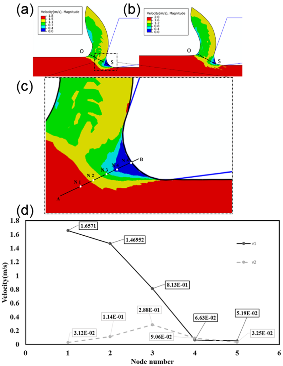
(a) Velocity distribution for a rounded tool edge, (b) velocity distribution for tool with DMC—Case 4
In Figure 7(a) and (b), a shear plane is defined as the line OS connecting the stagnation point (S) to the pre-flow zone and parallel to the velocity contour plot boundary between the region with the maximum workpiece velocity (red region in Figure 7(a)) and the region with the material velocity after entering primary deformation zone (yellow region in Figure 7(a)). Line OS is used as reference to extract representative values of quantities as the Von Mises stress, the equivalent plastic strain and temperature for further analyses (section “Workpiece stress, strain and temperature”).
Workpiece stress, strain and temperature
The maximum and minimum values of Von Mises stress, equivalent plastic strain and temperature along the shear plane OS (Figure 7(a) and (b)) have been extracted from FEM output and represented in Figure 8(A)–(C), respectively. All graphs show that the analyzed quantities depend on DMC.
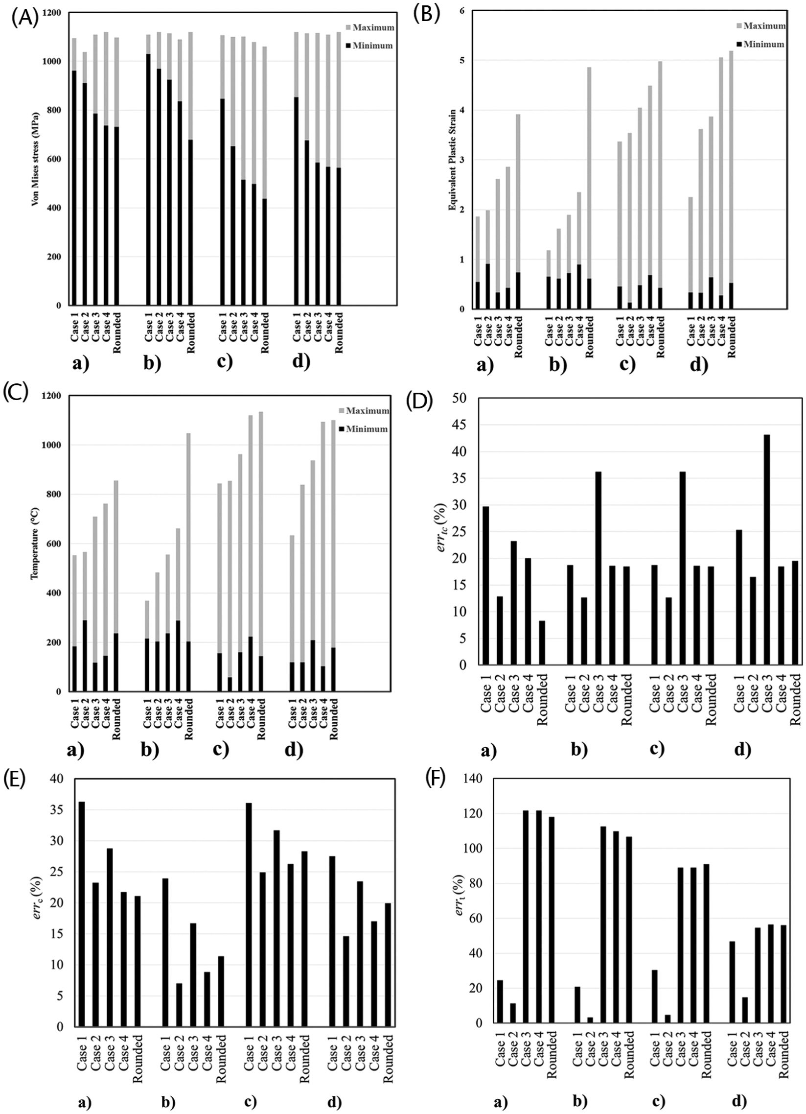
Results of FE simulation for (A) Von Mises stress, (B) strain, (C) temperature along line OS, (D) prediction error for chip thickness, (E) prediction error for cutting force and (F) prediction error for thrust force: (a) vc = 100 m/min, tu = 6 µm; (b) vc = 300 m/min, tu = 6 µm; (c) vc = 100 m/min, tu = 9 µm; and (d) vc = 300 m/min, tu = 9 µm.
Figure 8(A) shows that the difference between maximum and minimum Von Mises stress (gray part of the graph) is higher for simulations with rounded tool edge than in case of models with DMC (the lowest difference occurs for the DMC geometry of Case 1 for experimental conditions b, c and d. DMC changes the nature of tertiary shear zone that is caused by the friction between tool rounded cutting edge and workpiece.18,39 In fact, the DMC presence avoids the direct contact between tool edge and chip. In simulations with rounded edge tool (Figure 7(a)), the shear plane OS passes through both primary and tertiary shear zones and this can be the reason for a high stress variation (Figure 8(A)). However, in simulation with DMC (Figure 7(b)), the shear plane OS passes only through the primary shear zone because the tertiary shear zone is located under the DMC clearance face and above the DMC rake face.
Figure 8(B) and (C), respectively, shows the difference between maximum and minimum equivalent plastic strain and temperature along the shear plane OS. Both quantities assume the highest values for all machining conditions when simulations are performed considering a rounded tool edge, hence the DMC introduction decreases equivalent plastic strain and temperature on the shear plane. This fact means that the situation inside the chip is more homogeneous with the DMC introduction.
Chip formation
The chip formation provides a lot of valuable information about the metal cutting process. For example, the chip formation is of interest because the chip compression ratio (CCR) is an indicator of total plastic deformation of the target material. 40 In micromachining, where tool edge radius plays a fundamental role, the chip formation analysis becomes very important also because of the MUCT phenomenon. DMC affects the tool–chip interaction and, thus, the final chip thickness by changing the cutting operation geometry. For this reason, the DMC effect on chip thickness has been investigated by comparing FEM and experimental results.
Figure 8(D) shows the errors between the measured and the predicted chip thickness
As an example, Figure 9 depicts the chip geometry and the Von Mises stress distribution for the different DMC geometries and rounded tool edge in the cutting condition (c) (vc = 100 m/min, tu = 9 µm). The DMC rake face, which is associated to the angle

Stress distribution for different DMC geometries in the experimental conditions with vc = 100 m/min, tu = 9 µm: (a) Case 1
The DMC clearance angle
Cutting forces
The errors between predicted and experimental results for the cutting force (Figure 8(E)) and the thrust force (Figure 8(F)) point out that the DMC geometry has a strong influence on the cutting force prediction. In particular, introducing the DMC geometry of Case 2 allows a prediction performance improvement for both force components, except for the experimental condition (a) (vc = 100 m/min, tu = 6 µm) in case of cutting force (Figure 8(E)). In addition, DMC introduction is more effective in case of thrust force, for which the lowest percentage error is 3.14% for the cutting condition (b) with tu = 6 µm and vc = 300 m/min (Figure 8(F)). These results could support the assumption that Case 2 represents better, the real DMC, geometry.
Conclusion and future developments
This study aims to model and simulate the micro-orthogonal cutting in the presence of DMC in order to investigate the effects of this phenomenon on the micromachining process outputs (cutting force, thrust force and chip thickness) and stress distribution, equivalent plastic strain and temperature inside the workpiece shear zones. Current FE model approaches based on state-of-the-art assumptions cannot take into account the DMC stationary properties. For this purpose, a suitable FE model was developed by artificially introducing the DMC on the rounded tool edge and four DMC geometries were tested.
Based on the performed analyses, the following concluding remarks can be drawn:
Finite element simulations show how the Von Mises stress, equivalent plastic strain and temperature distribution on the shear plane are dependent on DMC presence and geometry.
By comparing experimental data with FEM results, it is shown how errors associated with cutting force, thrust force and chip thickness are highly sensitive to the DMC presence and geometry. The prediction performance of FE models can be significantly improved by introducing the DMC. For instance, it is possible to reduce the error between simulated results and experiments to less than 5% in case of thrust force predictions.
The DMC geometry of Case 2
According to FEM results, the DMC geometry of Case 2 also introduces a more homogeneous distribution of the Von Mises stress, equivalent plastic strain and temperature along the shear plane.
This study demonstrates how the DMC introduction in finite element modeling of micro-orthogonal cutting process is able to improve the simulation performances. Nevertheless, future studies will aim at improving the model prediction performances by a more accurate modeling of the tool–DMC–chip contact and the target material constitutive behavior.
Footnotes
Appendix 1
Declaration of conflicting interests
The author(s) declared no potential conflicts of interest with respect to the research, authorship and/or publication of this article.
Funding
The author(s) received no financial support for the research, authorship and/or publication of this article.