
Abstract
In this investigation, the attention is focused on the minimum bending radii of 2196-T8511 and 2099-T83 Al-Li alloy extrusions. To predict the failure of Al-Li alloys, sheet and extrusion stretch bending tests are developed, carried out and simulated using finite element model. The theoretical minimum bending radius is introduced to derive a safe lower limit for the bending radius which can serve as a guideline for tool and product design. Stretch bending tests of Al-Li alloys are performed using the three-point bending test and displacement-controlled stretch bending test at room temperature. The finite element model incorporates three-dimensional solid elements and ductile damage modeling. The experimental results show that Al-Li alloy extrusions in stretch bending show three types of failures, occurring at the unbent region near the entrance of the jaws, at the region below the exit of the die and within the region in contact with the die, respectively. Comparison between predicted values and experimental results has been made, a consistent agreement being achieved, reflecting the reliability of the present model. The three types of failure mechanisms which compete with each other are tensile localization failure, die-corner failure and shear failure, respectively. Based on the analytical models, experiments and simulations, it appears that the three distinct failures need to be applied to predict the minimum bending radius and range of failures that can occur with 2196-T8511 and 2099-T83 Al-Li alloy extrusions in stretch bending.
Keywords
Introduction
Nowadays, the application of Al-Li alloy bent extrusions as structural components becomes an important way to reduce the weight, increase the payload and improve the fuel efficiency of aircraft. 1 Automated assembly as well as limitations in the residual stresses allowed, and similar reasons, lead to the demand for highly precise bent extrusions. Among various extrusion bending methods 2 such as press bending, rotary stretch bending, roll bending, rotary draw bending 3 and pushing bending, 4 stretch bending is a feasible one for achieving stable bending of the Al-Li alloy extrusions. Forming limit prediction is important for practical application to determine the minimum dimension for a bent component of Al-Li alloys.
Banabic 5 has given a classification of the most important classical methods used in the theoretical prediction of Forming Limit Diagrams since the classic works of Swift 6 and Hill 7 on theoretical prediction of the diffuse and localized necking. Nevertheless, most of these models are applicable only to highly ductile materials. For such ductile materials, failure is typically related to sheet metal instability and the Marciniak–Kuczyński model 8 is extensively used for the prediction. However, the failure mechanism of high-strength materials, such as advanced high-strength steels, high-strength aluminum and Al-Li alloys, is different from that of highly ductile materials. In such materials, void nucleation and growth and shear band localization compete with instability. 9 In theory, failure can be examined in different scales (microscopic, mesoscopic and macroscopic). 10 The microscopic material failure is related to crack initiation, growth and propagation. The most popular failure models are micro-mechanical models, which combine continuum mechanics and classical fracture mechanics. 11 These models are based on the assumption: microvoid nucleation, growth and coalescence of neighboring voids. Finally, the macroscopic fracture results when macrocracks occur. It is known that the first model of this type was proposed by Gurson 12 and extended by Tvergaard 13 and Needleman and Tvergaard.14,15 Another approach is based on continuum damage mechanics (CDM) and thermodynamics and was proposed by Rousselier.16,17 Macroscopic material failure is defined in terms of critical load, strain or energy storage. Considering bending effect on failure, Leu 18 proposed a criterion for determining the bending limit (minimum bending radius) in pure bending, based on the principle of maximum bending moment. Demeri 19 developed formability tests simulating stretch bend conditions for simple angular and hemispherical contours and produced families of (RtH) curves relating the punch radius (R) and sheet thickness (t) to the height of the configuration at failure (H). Yoshida et al. 20 theoretically obtained fracture limits in sheet stretch bending on the assumption that the fracture occurs when the stretching force reaches its maximum value. El-Domiaty and colleagues21–23 and Paulsen and Welo 24 introduced the failure modes of the stretch bending process for T-section, U-section and rectangular section beams and the safe region for forming was given based on the outer layer was less than the necking strain (ε = n).
In the case of stretch bending for Al-Li alloy extrusions, process control and finite element (FE) simulation were reported in 2012 25 and theoretical, experimental and simulated formability prediction were reported in 2013. 26 The experimental results show that cold stretch bending of 2099-T83 and 2196-T8511 Al-Li alloy extrusions is feasible.27,28 Because of their high ultimate tensile strengths (UTS) (particularly relative to yield stress), the minimum bending radius of Al-Li alloys also has important technological interest. In this article, in order to answer this question, two sets of experiments are designed in accordance with the type of the forming processes normally used in the aircraft industry. The first series of the three-point bending test is used to determine the fracture limit of sheet stretch bending. The second series of the displacement-controlled stretch bending test represents the stretch bending processes used in the aircraft industry. Once the experimental fracture limits of sheet stretch bending are determined, a theoretical approach is used to predict the minimum bending radii of the extrusions. The experimental results are compared with the theoretically predicted results. FE simulations are carried out for comparison with experiments.
Minimum bending radius model
The extrusion with Z-section of up flange width, a, down flange width, b, height, h, flange thickness, t, and web thickness, t, is shown in Figure 1(a). Point O of Z-section is set as the origin of coordinate, the plane coinciding with this cross-section and bending plane are set as coordinate planes to establish the Cartesian coordinate system Oxyz. In the coordinate system, the axis x is perpendicular to all the cross-sections. The longitudinal section xOz is the bending plane. The height of cross-section is h. Point C is the centroid of Z-section. The distance of point C to the centroidal axis x is zc. The width of cross-section is w(z) which is a function of z. Loading method of tension and moment is shown in Figure 1(b). First, the axial tension T is applied at the two ends of the profile and then the bending moment M is applied. The magnitude of the tension T is constant and the direction is always along the centroidal axis of profile when bending. R is bending radius of the centroidal axis.
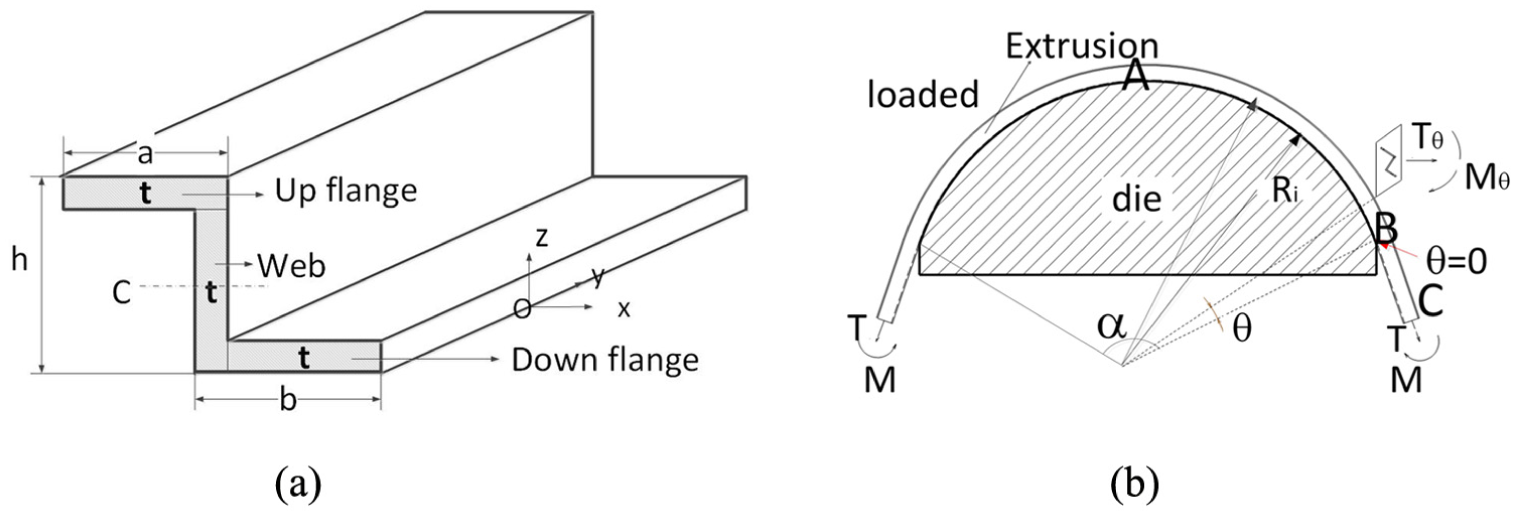
Stretch bending of Z-section extrusion: (a) undeformed extrusion and (b) deformed extrusion.
In order to reduce the complexities involved in analysis, the following simplifying assumptions are made for the formulation of the mathematical model:
Plane sections remain planar throughout deformation. In bending an extrusion to a bend radius more than three or four times the extrusion height, it may be assumed that a plane normal section in the extrusion will remain plane and normal and converge on the center of curvature.
The stress state is approximately uniaxial with only a circumferential stress. It will be assumed that the condition in each element is uniaxial tension or compression in the longitudinal direction rather than plane strain. Additional assumptions of the model are that no relaxation happens during strain reversal and volume is assumed constant during plastic deformation and the process is proportional. If we now restrict the analysis to isotropic materials, where identical properties will be measured in all directions, we may assume from symmetry that the strains in the width and thickness directions will be equal in magnitude and hence
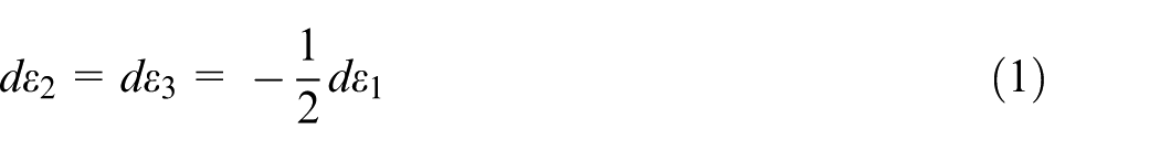
where dε1, dε2 and dε3 are the principal strain increments.
Neutral axis is zero-extension fiber. Since the radius of the forming die is much greater than the height of the extrusion, the axial strain is linearly proportional to the distance from the neutral axis.
Isotropic, homogeneous material behavior is assumed. Young’s modulus is considered constant to the increase in plastic strain. Strain–stress relationship is assumed to fit the function

The stress component σ is described elastoplastically as
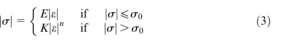
where E is Young’s modulus, σ0 is the yield stress and K and n are strain hardening constants.
Coulomb friction is assumed

where τ, µ and p are shear stress, friction coefficient and pressure between the tool and the extrusion. The sign is determined by the direction of relative motion between the tool and the extrusion.
Analysis of stretch bending
The model is symmetrical at θ = α/2, so only half of it is considered during the analysis. For stretch bending analysis, a complete strain history for “stretching–bending–stretching” is required. At the end of pre-stretching, a certain amount of pre-stretching strain, εpre, and stress, σ(εpre), have occurred in the whole cross-section. Industrial practice is to pre-stretch parts into the plastic range,29–33 and stretch bending is performed under constant jaw trajectory. We assume constant force at the symmetrical section is being used in this analysis. Thus, the strain component ε1 at the end of the stretch bending stage is given by
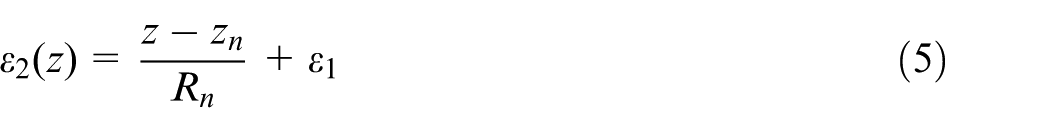
where z is the through-height coordinate, taking values between 0 and h, h represents height, Ri is inner surface radius and εt denotes the axial strain. The parameters R and εt are kinematic boundary conditions, that is, they are geometric quantities chosen independently to represent the one bending state of the model. The position of the neutral axis, zn, depends on the tension force or the tensile strain εt. For a Z-section extrusion, T and M can be written as
Solving the equilibrium equation leads to the well-known capstan model which gives the tension variation caused by friction

where T0 is the tension force applied at the end of the extrusion where θ = 0. The sign of the exponential depends on the direction of the friction force.
The maximum tension force (at θ = 0) and maximum moment (at θ = α/2) at the end of the stretch bending stage for a extrusion can be evaluated by
Diffuse necking rule
Elsharkawy and El-Domiaty 22 and Paulsen and Welo 24 introduced the failure models of the stretch bending process for T-section, U-section and rectangular section beams and the safe region for forming was given based on the outer fiber was less than the necking strain, which agrees with FLD0. If a simple diffuse necking criterion is employed (ε = n) together with equation (5), diffuse necking takes place if the following condition is satisfied
where εo is outer surface stain.
An easy and practical approximation for the minimum bending radius on the inner surface of bent part is then obtained based on global necking criterion as follows
Stretching bending limit
During stretch bending, flow stress of the sheet, σ, is increasing with outer surface strain εo because of its work hardening; on the other hand, the height of the extrusion h is decreasing. As a result, tensile force T is initially increasing rapidly with εo, but the rate of increasing load is decreasing, and it will reach its maximum value. Yoshida et al. 20 proposed the following regression equation, as shown in Figure 2, for sheet stretch bending
Schematic of sheet stretch bending model.
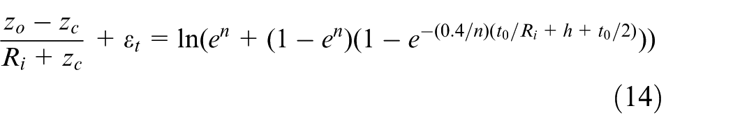
For the Z-section extrusion in stretch bending as shown in Figure 1(a), the majority of the bending moment is supported by the flanges and the failure usually occurs at the outer flange region. The webs can be neglected in the analysis, 34 and the fracture limit of up flange can be written as equation (14)
It is known that Masatoshi Yoshida’s model is proposed with plane stress state, a new model is developed for stretch bending of extrusion. Based on uniaxial stress assumption, the force of the outer flange region is evaluated using equation (1)
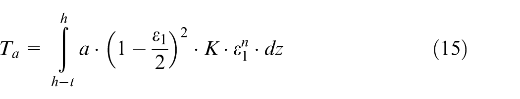
where limit axial strain ε1 is a function of εt (see equation (5)). The region is assumed to be deforming plastically. Combining this with equation (3) and equation (1), we obtain
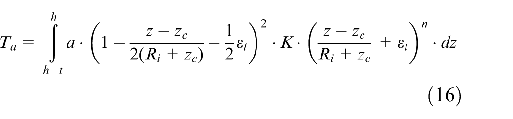
During stretch bending, flow stress of the outer flange sheet, σ, is increasing with axial strain ε1 because of its work hardening; on the other hand, the thickness of the outer flange is decreasing. As a result, tensile force Ta is initially increasing rapidly with ε1, but the rate of increasing load is decreasing, and it will reach its maximum value Tamax. The maximum load Tamax and limit axial strain ε1 are determined by numerically calculating equation (16) until
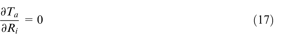
It should be noted that Rmin is determined uniquely for a given n, K, a, h, zc, t and εt using equation (17). An easy and practical approximation for the minimum bending radius is then obtained based on force limit criterion.
Bending limit
The proposed criterion for the bending limit (BL) states that the limit is determined by the principle of maximum bending moment. 18 Considering the decreasing thickness of the flange, the moment of the outer flange region is evaluated using equation (7)
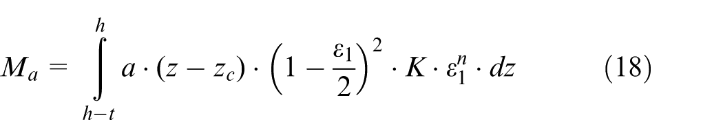
The region is assumed to be deforming plastically. Combining this with equation (3) and equation (1), we obtain
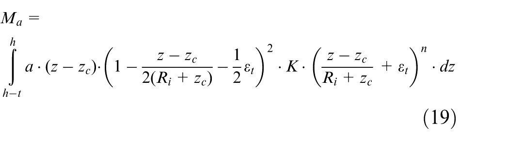
During stretch bending, bending moment Ma is initially increasing rapidly with ε1, but the rate of increasing moment is decreasing, and it will reach its maximum value. The maximum moment Mamax and limit axial strain ε1 are determined by numerically calculating equation (19) until
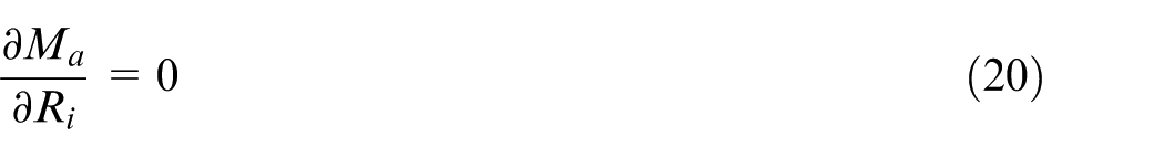
It should be noted that Rmin is determined uniquely for a given n, K, a, h, zc, t and εt, using equation (20). An easy and practical approximation for the minimum bending radius is then obtained based on moment limit criterion.
Experiment and simulation
Material
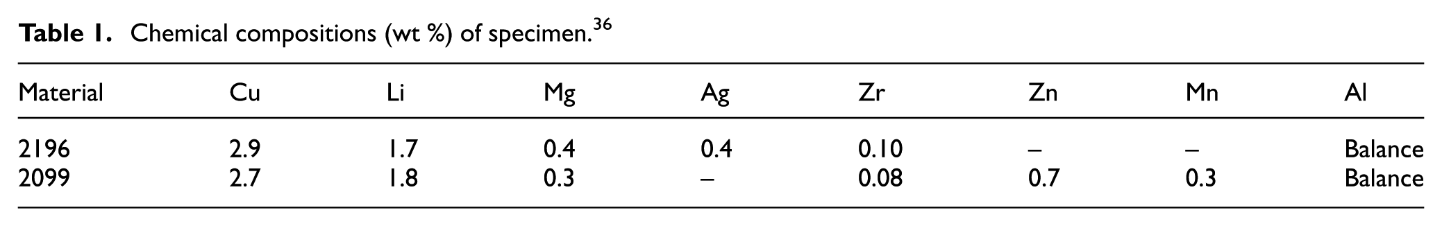
Dogbone-shaped specimens are obtained from the extruded 2099 and 2196 aluminum–lithium alloys with Z-section and T-section (shown in Figure 3) using wire-electrode cutting. The chemistry of the two Al-Li alloys appears in Table 1. Two aluminum–lithium (Al-Li) alloys of the latest generation are qualified by Airbus and currently applied in the A380 program which offer high static strength and lower density compared to the current 7000 alloys. 35 In this study, the temper of 2196 Al-Li alloy is T8511: extruded, solution heat treated and stress relieved by stretching to produce a nominal permanent set of 2.5%, but not less than 1% nor more than 4%, and aged (AMS4416); and the one of 2099 Al-Li alloy is T83: solution heat treated and stress relieved by stretching to produce a nominal permanent set of 1%–4% and then artificial aged (AMS4287).
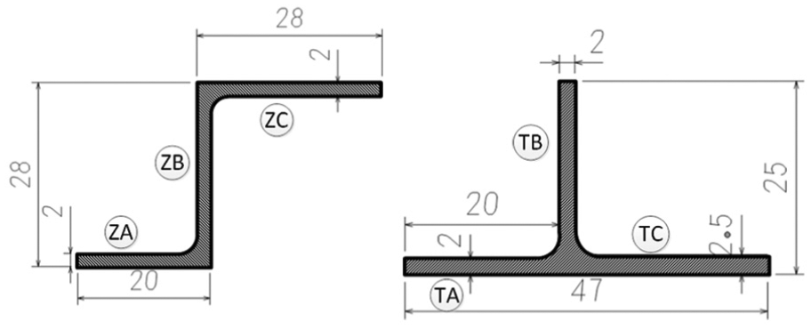
Schematic diagram of extrusion cross-section.
Chemical compositions (wt %) of specimen. 36
Tensile testing
Uniaxial tension tests were conducted for four materials in extrusion direction at a nominal strain rate of
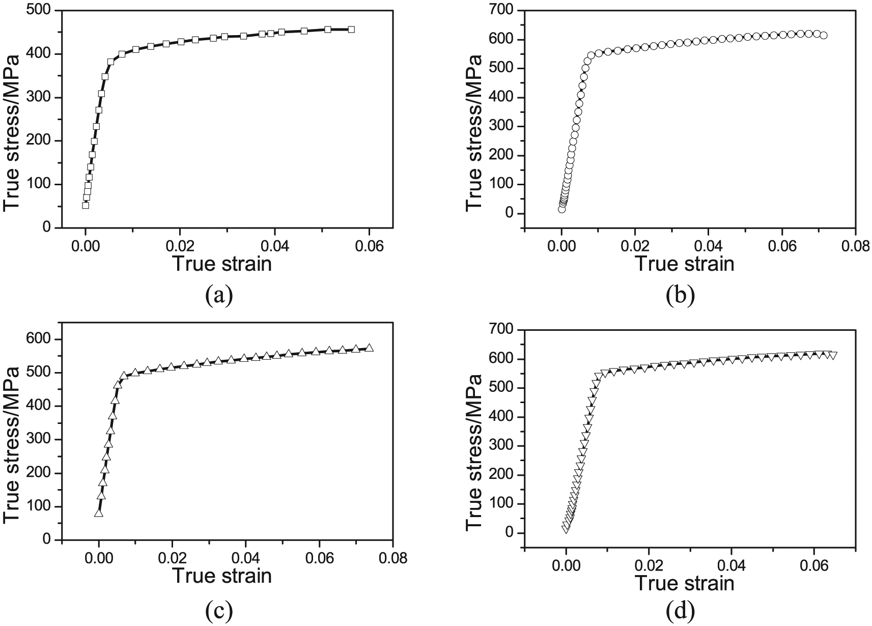
True stress–strain curve of Al-Li alloys: (a) 2099-T83 Al-Li alloy extrusion with T-section, (b) 2196-T8511 Al-Li alloy extrusion with T-section, (c) 2099-T83 Al-Li alloy extrusion with Z-section and (d) 2196-T8511 Al-Li alloy extrusion with Z-section.
Mechanical properties of specimens.
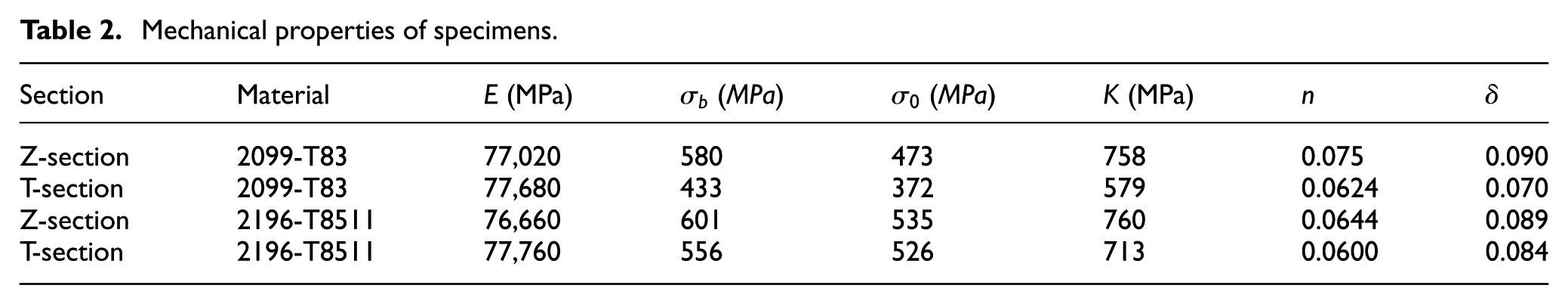
The variation in the material properties of Al-Li alloys with respect to the factor “sidewall” was studied in the traditional way. The different locations effect in the longitudinal direction at the same sidewall was neglected. Uniaxial tension tests were performed using test specimens machined from three sidewalls, in the extrusion direction. Three specimens were manufactured at the same sidewall in the longitudinal direction. All specimens were taken in the extrusion direction and at the middle position of the web or sidewall for the extrusions, respectively. It was assumed that the mechanical properties were normally distributed, and the mean mechanical properties were calculated and shown in Table 2.
Stretch bending tests of Al-Li alloys
Stretch bending tests of Al-Li alloy sheets
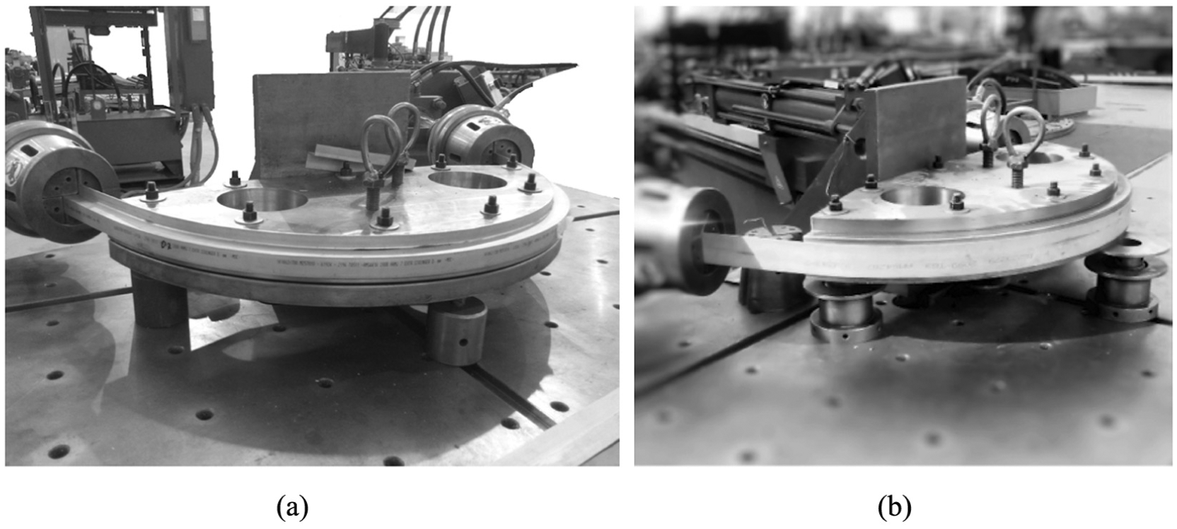
For the verification of the above stretch bending limit fracture criterion, three-point stretch bending tests were performed. In the tests shown in Figure 5, both ends of sheet specimens were firmly clamped and stretch bent by a punch. To examine the effect of the bending radius, five different punches with radii of 10, 20, 30, 40 and 50 mm were employed. Two types of Al-Li alloy sheets were used.
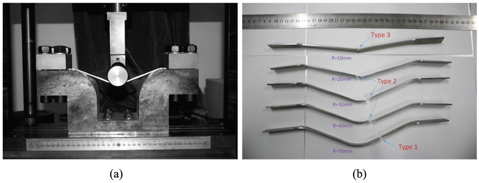
Photographs of stretch bending test: (a) experiment device and (b) fractured 2196 Al-Li alloy specimens.
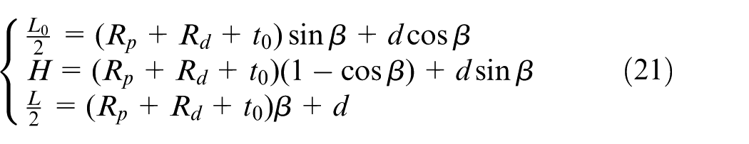
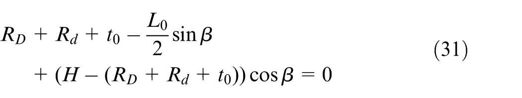
Limit forming height Hmax is often used as a measure of forming limit in real stamping operations. For that purpose, equations are derived for calculating limit forming height Hmax (see Figure 2). They include the limit wall length Lmax which can be determined by equation (21), as well as some geometrical parameters such as die radius Rd, punch radius Rp, die span L0, contact angle β, linear length d and sheet thickness t0
Fractured 2196 Al-Li alloy specimens are shown in Figure 5(b). The fracture of the three types of Al-Li alloy sheets mostly occurred at the bent area for R = 10 mm, linear range for R = 50 mm and punch corner for R = 20, 30 and 40 mm.
Al-Li alloy extrusion stretch bending test
The experiments were conducted using the A-6B CNC displacement-controlled stretch bending machine. It is a 15-metric ton stretch-forming machine for use in the aerospace manufacturing industry for the purpose of stretch wrapping extruded or formed parts. Unlike typical load controlled stretch wrap forming machines, this machine consists of a stationary die table and two arms hinged to the table independently actuated by hydraulic cylinders. Tension cylinders are mounted on carriages, which can be moved along the arms. Each cylinder can be equipped with a jaw for holding a workpiece during the stretch bending forming operation.
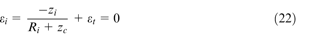
In the stretch bending process, for avoiding the wrinkling, reducing the springback and ideal accuracy, a good method is to increase additional tension and shift the neutral axis from the middle layer to the bottom surface (Ri position). The minimum bending radius under the condition (εi = 0) is useful for engineering design. Thus, εi can be estimated by
Then the minimum bending radius is determined by numerically calculating using proposed diffuse necking rule (DNR), proposed stretching bending limit (SBL), proposed BL and derivation of Yoshida’s model (YM). The results are shown in Table 3, and the minimum bending radius ranges from 351 to 455 mm. For the cost reason, two dies with radii of 400 and 426 mm are chosen for experiment.
Analytical minimum bending radii of four rules.
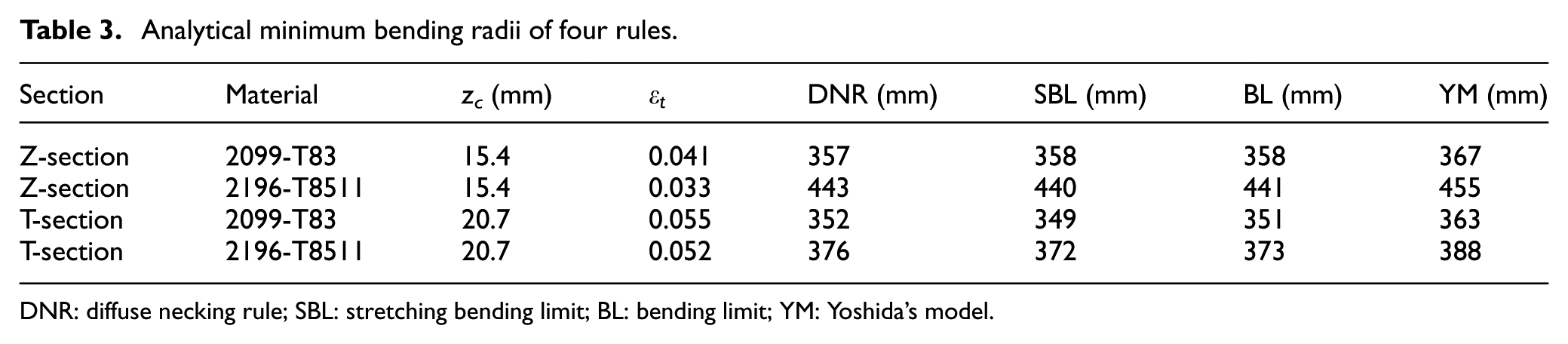
DNR: diffuse necking rule; SBL: stretching bending limit; BL: bending limit; YM: Yoshida’s model.
The machine goes through several stages when forming a part. In pre-stretching step, the part is typically stretched to its yield point. In stretch bending step, the arms move to the BL and the tension cylinders follow the part program values which are recorded data plus any added stretch. The base values are generated by the “sensor record” process. In post-stretching step, the part is stretched a distance. During the experiment, 2196 and 2099 Al-Li alloy extrusions with Z-section and T-section with dimensions of cross-section as shown in Figure 3 and effective length, 1500 mm, were formed over two dies with radii of 400 and 426 mm (with an 150° sweep), as shown in Figure 6.
Photographs of stretch bending test of (a) Z-section and (b) T-section extrusions.
The failure location was used to discern the failure type in the experiments. Figure 7 shows photographs of three types of stretch bending failures of Al-Li alloy extrusions.
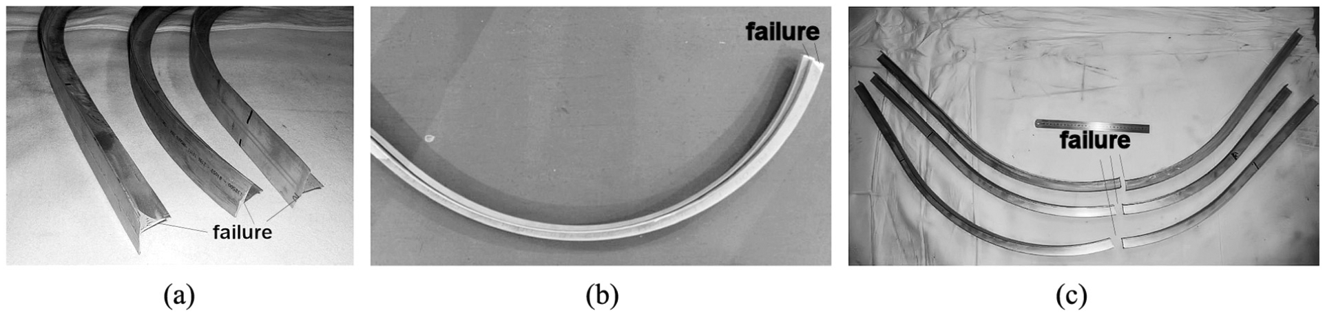
Three types of stretch bending failures of Al-Li alloy extrusions obtained by experiments: (a) Type 1, (b) Type 2 and (c) Type 3.
FE analysis
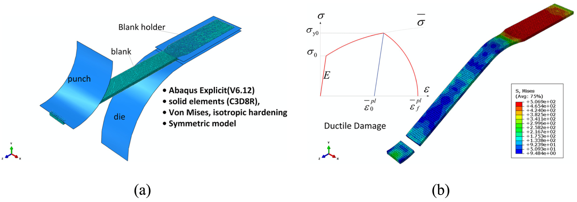
Two loading cases are considered. The first case consists of a quasi-static three-point bending configuration using five models. In the second case, the part is subjected to a quasi-static stretch bending using two models. The 2196 and 2099 Al-Li alloys were simulated using the ABAQUS software. In order to reduce the simulation time, a half of the geometric model was used and a symmetry condition was imposed to the blank. The tools were modeled as discrete rigid bodies and the blank as deformable body with C3D8R solid elements. The element size was equal to 1 mm and the ductile damage model was used. The mechanical properties of the material are indicated in Table 2 and Figure 4. Both the analyses consider geometric nonlinearity and use automatic time incrementation using element-by-element stable time increment estimates. A general contact interaction is defined between the deformable bodies and rigid bodies. A constant friction coefficient is used for all of the contact interactions in this case. A penalty-type mechanical constraint is used for all of the contact pair definitions. The smooth step is used to define the smooth loading of all the above tools to reduce inertial effects in explicit simulation of the quasi-static process. Energy output variables are requested for the entire model, the value of the kinetic energy (ALLKE) is less than a small fraction (e.g. 0.1) of the value of the strain energy (ALLIE). 37
Ductile damage and friction coefficient
Abaqus/Explicit offers a number of damage initiation criteria to model the onset of necking instabilities in sheet metals. In this article, we choose the ductile criterion of damage initiation criteria for the fracture of metals. The ductile criterion is a phenomenological model for predicting the onset of damage due to nucleation, growth and coalescence of voids. The model assumes that the equivalent plastic strain at the onset of damage is a function of stress triaxiality and strain rate. Damage evolution occurs once the damage initiation criteria are satisfied. Plastic displacement-based linear damage evolution law is used for ductile damage initiation criterion. The value of the plastic displacement at which the damage variable reaches 1 is taken as 0.1. The default maximum degradation rule is used, and the elements are removed from the mesh once the maximum degradation has occurred. The plastic stress–strain curve is fitted using the following equation

However, after the onset of necking, equation (23) cannot be used because the formation of a neck introduces a complex triaxial state of stress in that region. Then the extend curve based on equation (3) is input to plastic property. In this phenomenological hardening model, the parameters K, ε0 and n are identified through the available pre-necking data. When nominal load F reaches a maximum value, namely, σb, the relation εb = n is determined. It is believed that the true plastic strain at the peak load is equal to the strain hardening exponent (n). On the basis of CDM and microscopic damage mechanics, the stress–strain curve characterized by a power function 38 at the room temperature is with a fracture stress in equation (24)

where q is the material damage parameter, and q = 1 and q = 9/4(1 − υ) are corresponding to uniform and non-uniform deformation stage divided by nominal ultimate strength (NUS), respectively.
The fracture stress can also be illustrated by the strength coefficient K as in equation (25)

and the corresponding fracture strain in equation (26)

The commonly used Rice–Tracey fracture model 39 in the three-dimensional (3D) space reads

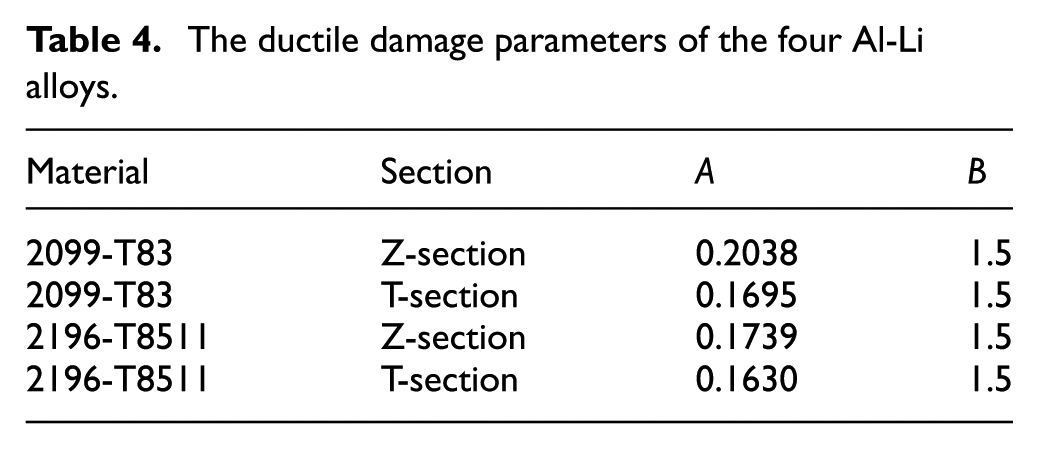
where A and B are two coefficients of the exponential function to calibrate. The fracture strain
The ductile damage parameters of the four Al-Li alloys.
For the verification of the failure parameters, the proposed constitutive equation was tested using a FE model of a tensile test with the same specimen geometry as in the experiments. Solid elements (C3D8R) were used for dynamic/explicit simulations with two element layers through the thickness. A von Mises yield function and the isotropic hardening law were adopted for simplicity. The simulation accuracy was evaluated based on the comparison of displacement with experiments at this same load as shown in Figure 8. The results show that the failure parameters are reliable in plastic localization prediction and failure.
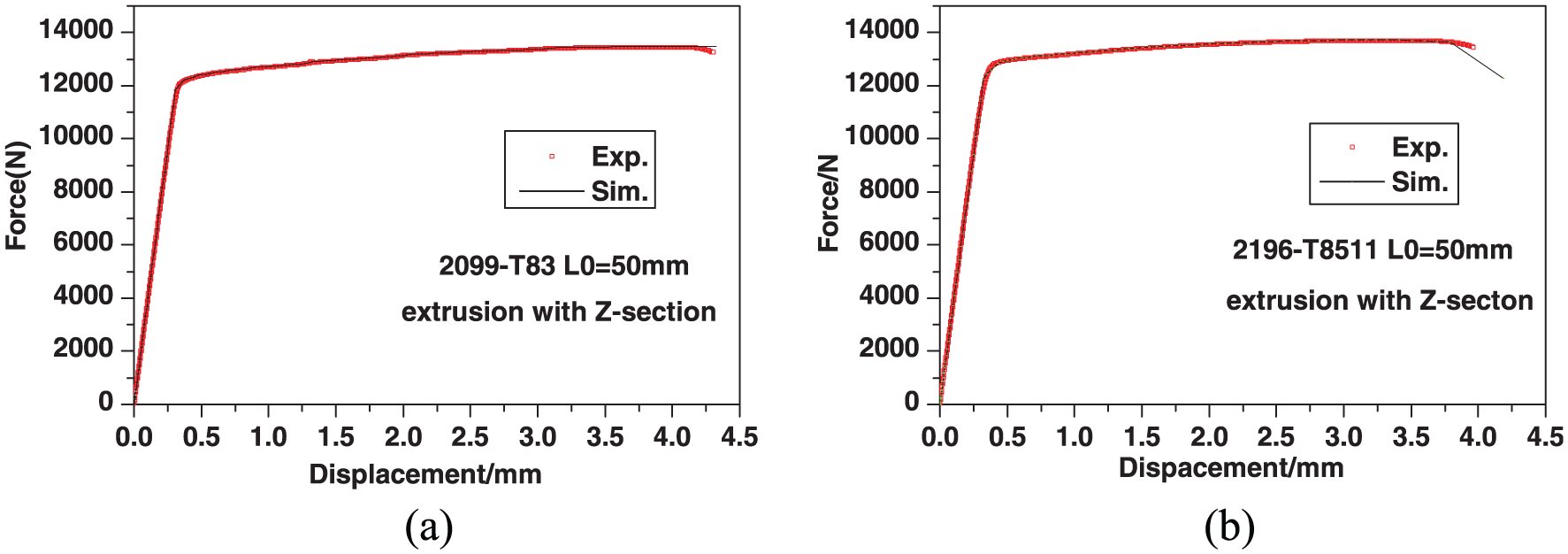
Comparison of force–displacement curve between experiment and simulation of tension test: (a) Z2099-T83 and (b) Z2196-T8511.
In addition, a method to identify the friction coefficient is proposed using equation (25). As shown in Figure 2, the equilibrium equation for forces of bent element in the radial direction is 41

One part of element force in the radial direction results in the vertical force of punch

Integrating the vertical force of the bent element, the vertical force of punch is evaluated by
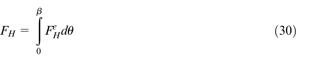
Combining equation (21), we obtain β
When fracture occurs, the tension at β is evaluated using fracture stress σf

where A is the section area of sheet. Then the friction coefficient µ identification is implemented based on several experimental tests by measuring maximum forming height and corresponding vertical force of punch. It is shown that the friction coefficient is approximately 0.11. Considering the same material of two types of stretch bending experiment, this friction coefficient is used as penalty contact formulation between the material and the tool in simulation.
Al-Li alloy sheet stretch bending simulation
The three-point bending simulation, shown in Figure 9, consists of two explicit dynamic steps (blank hold step 1 and bending step 2). The simulation times are 0.1 and 0.3 s, respectively. In step 1, the pressure load at blank holder applies the hold force. All of the degrees of freedom are constrained at the reference nodes of the punch and die. In step 2, a displacement/rotation boundary condition is specified at the reference node of the rigid punch in the global Y-direction. To examine the effect of the blank holder pressure and friction coefficient, three blank holder pressures (200, 300 and 400 MPa) and three values of friction coefficient (0.11, 0.15 and 0.2) were used. To examine the effect of the bending radius, five different dies with radii of 10, 20, 30, 40 and 50 mm were employed.
Stretch bending simulation of Al-Li alloy sheet: (a) model and (b) result.
Al-Li alloy extrusion stretch bending simulation
The stretch bending simulations, shown in Figure 10, of Z-section (die radius Ri = 400 mm) and T-section (die radius Ri = 403 mm) extrusion consist of three explicit dynamic steps (pre-stretching step 1, stretch bending step 2 and post-stretching step 3). The simulation times are 0.1, 0.3 and 0.1 s, respectively. In step 1, the pressure load (p1) at extrusion end applies the pre-stretching force. So the axial strain can be evaluated by
combining with equation (6). All of the degrees of freedom are constrained at the reference nodes of the die in three steps.
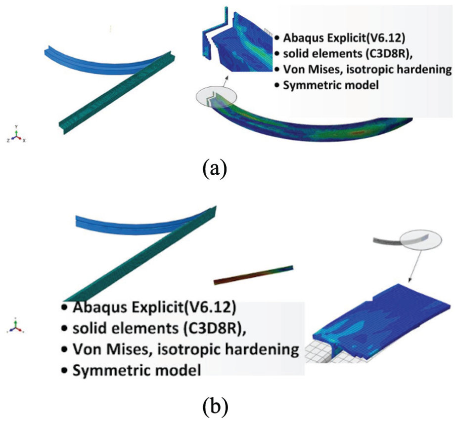
Stretch bending simulation of Al-Li alloy extrusion: (a) Z-section simulation and (b) T-section simulation.
In step 2, a displacement/rotation boundary condition is specified at the reference node for coupling of the extrusion end nodes in the local coordinate system. The axial force remains unchanged and a rotation displacement (equal to bending angle) is specified at the reference node for bending. In step 3, the pressure load at extrusion end applies the post-stretching force. The cross-section consists of 180 elements. In the longitudinal direction, 750 elements are used along the deformable part with increasing element size toward the ends of the specimen.
Results and discussion
First, both the analytical and numerical models are evaluated. Then, the failure types of the Al-Li alloy extrusions in the cold stretch bending are studied under minimum bending radius.
Comparison of fracture limit of Al-Li alloy sheet under stretch bending
For the verification of the stretching limit, three-point stretch bending tests were performed. Two types of Al-Li alloy sheets (2196-T8511 and 2099-T83) with 2.0 mm thickness, 12.0 mm wide and punch radii of 10–50 mm were used. By comparing with the experimental results, both the above analytical and FE models have been verified. In the quasi-static simulation of the stretch bending process, the stability requirements result in very small time steps and consequently a large computational time. In this work, however, the problem is overcome by introduction of mass scaling (factor = 10). The applicability of this approach is demonstrated comparing the results from similar analyses performed with the implicit ABAQUS.
A series of simulations with different friction coefficients and holder forces were carried out using the shell element model (implicit) for the R = 40 case, and the vertical force versus displacement responses of the punch are compared with the test result in Figure 11(a) and (b). It can be seen that the friction coefficient and holder force have little effects on the vertical force versus displacement responses of the punch.
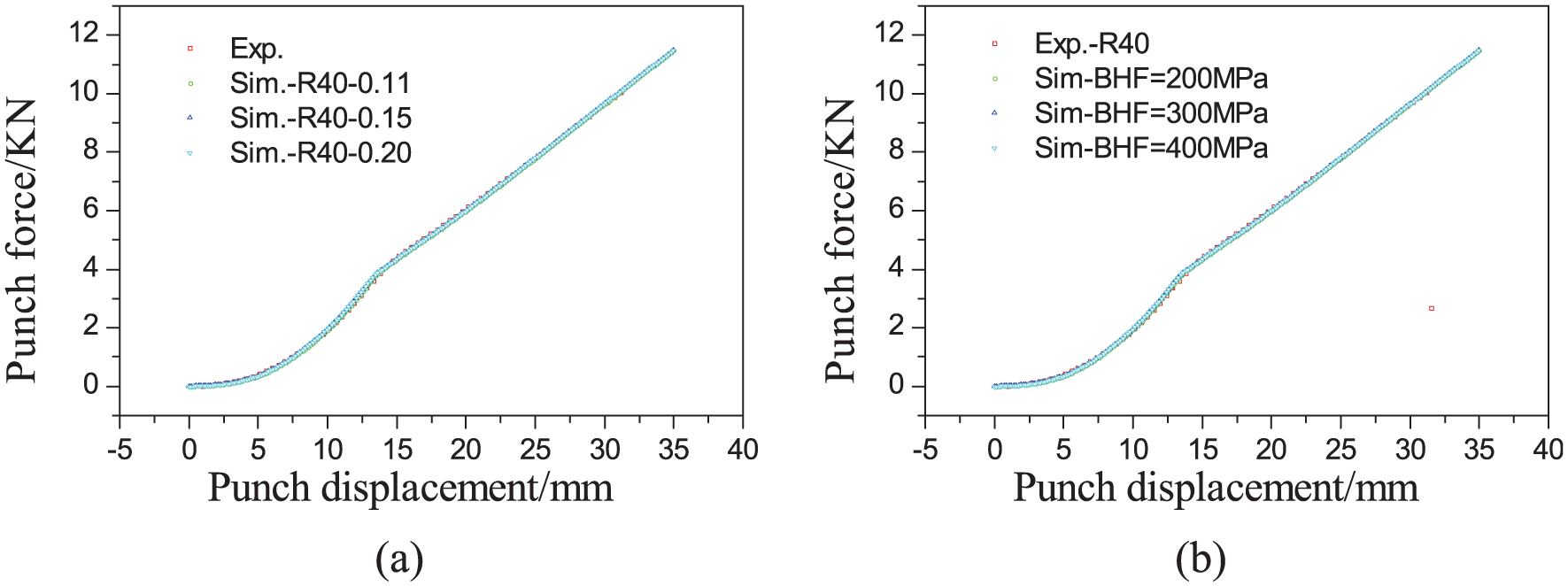
Comparison of punch load versus displacement responses of simulations with different friction coefficients and holder pressures against experimental data: (a) different friction coefficients results and (b) different holder forces results.
Figure 12 shows the comparison of experimental data of limit forming height with the corresponding results of calculation by equation (14) and FE simulation. From this figure, the limit forming height increases with increasing R, and the variation trends of the limit forming height among experimental results, simulation results and theoretical prediction results are extraordinarily similar; the values of the average error of the limit forming height of 2099-T83 are 3.8% (analytical prediction) and 22.3% (simulation), respectively. And the average errors of 2196-T8511 are 11.8% (analytical prediction) and 5.2% (simulation), respectively.
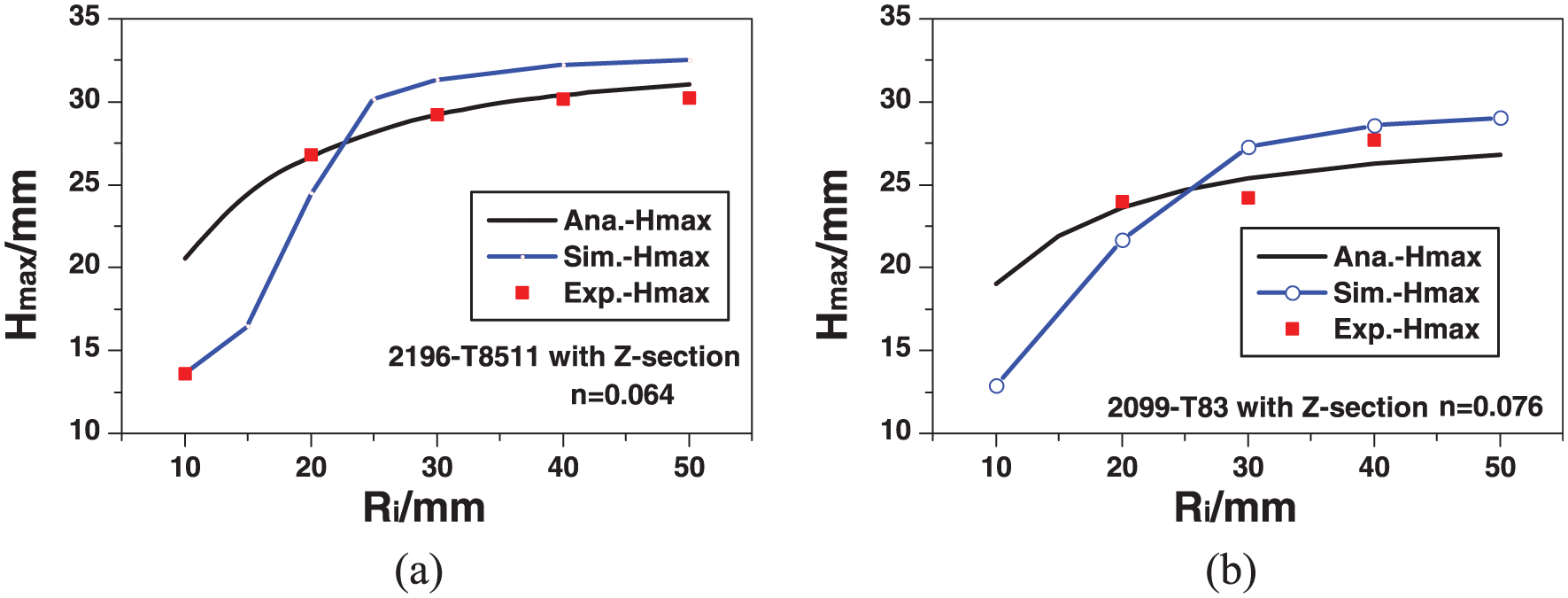
Comparison of limit forming height between experiment and calculation: (a) Z2099-T83 and (b) Z2196-T8511.
The reason for discrepancy is as follows: the predicted limit forming height is obtained under the theory critical condition which die radius is infinitely great. In experiment, it is obtained under the condition which the die radius is 60 mm. In fact, the limit forming height may have been reduced by lower die. For this reason, the limit forming height obtained by theory prediction is larger than that obtained by experiment. Although the experimental conditions were widely scattered, the calculated and simulated results of limit forming height for Ri are in good agreement with the experimental data. However, the variation trends of the limit forming height between simulation results and theoretical prediction results are a little different in punch radius Ri = 10 mm as shown in Figure 12(b). The reason is that the analytical model is proposed based on linear strain distribution in thickness direction. If the radius of the bend is approximately close to the sheet thickness, a more refined analysis is necessary. The importance of this strain reversal is that it must be taken into account in determining the effective strain in a material element at a particular distance from the middle surface. 41
Comparison of fracture limit of Al-Li alloy extrusions under stretch bending
For the verification of the minimum bending radius, displacement-controlled stretch wrapping tests were performed. Two types of Al-Li alloy extrusions (2196-T8511 and 2099-T83) with Z-section and T-section were used. Figure 13(a)–(d) shows the experimental results along with correlations and prediction for 2099-T83 with Z-section, 2196-T8511 with Z-section, 2099-T83 with T-section and 2196-T8511 with T-section Al-Li alloy extrusions at room temperature, respectively.
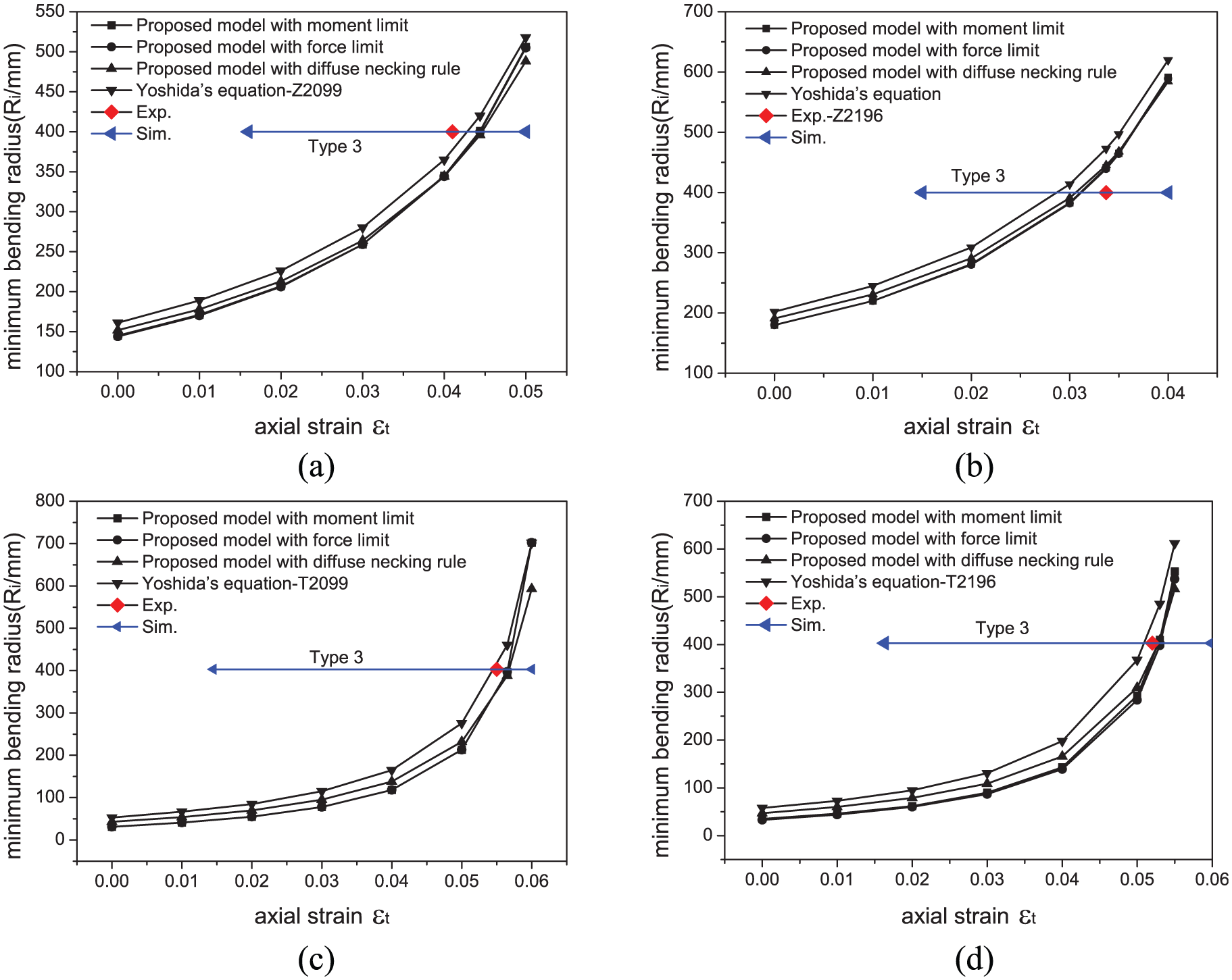
Comparison of minimum bending radii of the four types of Al-Li alloys between experiment and calculation: (a) 2099-T83 with Z-section, (b) 2196-T8511 with Z-section, (c) 2099-T83 with T-section and (d) 2196-T8511 with T-section.
From this figure, the value of the maximum error of the minimum bending radius model is less than 10.9%, 9.6%, 7.3% and 9.7%, respectively. The reason for analytical discrepancy is as follows: (1) the predicted minimum bending radius is obtained under the theory critical condition without the occurrence of wrinkling and crack. In experiment, the minimum bending radius is obtained under the condition which no wrinkles are observed by experimenter. In fact, the micro-wrinkles and micro-cracks may have been produced. For this reason, the minimum bending radius obtained by theory prediction is larger than that obtained by experiment. (2) In the stretch bending process of Al-Li alloy extrusions, the tangent axial stress can be reduced by the friction force at contact interfaces between the extrusion and the die. Thus, the external work can be reduced and then the failure tendency is decreased. The frictionless condition in the theoretical model may cause the external work to become larger than that in practical experiment. As a result, the frictionless condition in the theoretical model predicts a larger minimum bending radius than the experimental observation.
In addition, maps of failure type 3 and axial strains have been measured and simulated with good accuracy. However, the type 1 failure occurs in simulation only when extrusion is stretched in post-stretching step. It is different from experimental result because it occurs in stretch bending step as well as post-stretching step. The main reason is that axial force increases in bending while it is constant in simulation. Therefore, tension force has an important effect on type 1 failure. On the other hand, type 2 failure has a mixed appearance that appears to initiate type 3 and it happens at the last moment of bending. For a given radius of die, type 2 failure occurs when axial strain is minimum one of type 3 failure.
Three types of failures
Figure 14 shows the three examples of the simulated failures of two types of stretch bending. In all three cases, the predicted failure types match the experimentally observed ones. In agreement with previous work, 42 Figure 7(a)–(c) corresponds to Type 1, Type 2 and Type 3, occurring at the unbent region near the entrance of the jaws (or lower die corner of sheet stretch bending), at the region below the exit of the tooling or punch (below the tangent departure point) and within the region in contact with the tooling or upper punch, respectively. The three failure types can be understood from a continuum mechanics viewpoint with DNR (equation (11)), SBL (equation (14)) and BL (equation (20)). During stretch bending, material loaded in tension is bent near the entrance of the die (A in Figure 1(b)) and turns toward the exit of the tooling (B in Figure 1(b)). Because of friction and bending, the tensile force T ramps up as the material moves around die contact. Meanwhile, the bending moment M ramps up from its tangent points to its center.
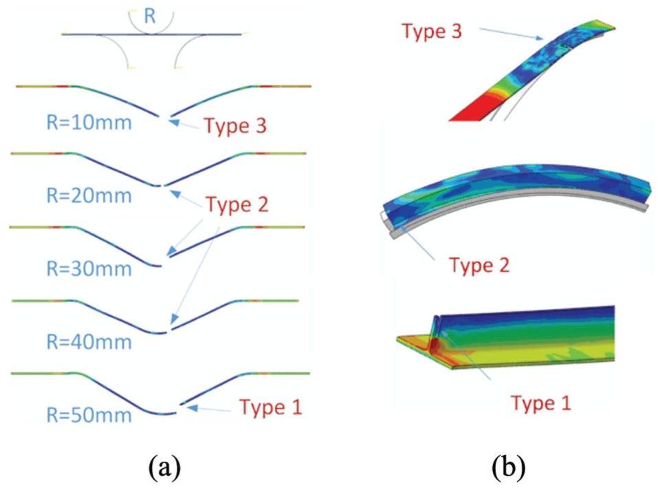
Three types of failures of simulation result: (a) sheet stretch bending failure and (b) profile stretch bending failure.
Type 1 failure occurs when the tension reaches the UTS of the material before the load limit is reached in the bending area. It is a normal tensile localization failure caused by stretching without bending. Type 1 failure is favored for large R/t which tends to raise the sustainable load in the bending region. The stress state approaches uniaxial and the tensile force is higher than the tensile force of the bent area.
Type 3 failure occurs when the moment reaches the maximum value sustainable by the bent extrusion and sheet. It is a shear failure. Type 3 failure is a result of localized necking during bending-under-tension (or possibly by a brittle stress/strain limit reached by the action of bending and increased tension around the contact region).
Type 2 failure occurs near the tangent departure point (near B in Figure 1(b). In profile stretch bending, material is drawn over a sharp radius of die entrance. The curvature of die corner is higher than one of die. It may be the same as Type 3 failure or die-corner failure due to stress concentration. However, it should occur only when the bending angle is more than design angle of bending. Therefore, there is another explanation for type 2 failure mechanism. In sheet stretch bending, although there is no sharp radius of upper punch entrance, type 2 failure occurs. Kim et al. 42 proposed that the material is softened by deformation-induced heating and thinning.
The results suggest that three distinct failures will need to be applied in industry to predict the range of failures that can occur with Al-Li alloy extrusions and sheets in stretch bending.
Conclusion
Minimum bending radius was observed in 2196 and 2099 Al-Li alloy extrusions. Room temperature mechanical property was tested as possible origins of the observed fracture limit behavior. To predict the failure of Al-Li alloys, two sets of experiments are designed in accordance with the type of the forming processes normally used in the aircraft industry. In this article, we propose three equations to determine the minimum bending radius, which can be solved numerically. Meanwhile, FE simulations were carried out for comparison with experiments. The following conclusions were drawn from experiment and analysis of minimum bending radii of 2196-T8511 and 2099-T83 Al-Li alloy extrusions:
The concepts of assured failure limit and minimum bending radii of 2196-T8511 and 2099-T83 Al-Li alloy extrusions in stretch bending have been introduced.
The minimum bending radius model of Al-Li alloy extrusions with Z-section and T-section in stretch bending was in good agreement with the experiments.
FE simulations for the forming limit of 2196-T8511 and 2099-T83 Al-Li alloys in sheet and extrusion stretch bending were in good agreement with the experiments.
Al-Li alloy extrusions in stretch bending tests show three types of failures, occurring at the straight region, at the region below the exit of the tooling and within the region in contact with the tooling, respectively. The three types of failure mechanisms which compete with each other are tensile localization failure, die-corner failure and shear failure, respectively.
Based on the analytical models, experiments and simulations, it is shown that the three types of failures need to be applied to predict the minimum bending radius and range of failures that can occur with 2196-T8511 and 2099-T83 Al-Li alloy extrusions in stretch bending.
Footnotes
Appendix 1
Acknowledgements
This work has been performed under the joint project between Northwestern Polytechnical University and AVIC Xi’an Aircraft Industry (group) Company Ltd (XAC). The authors are grateful to the many, many helpful discussions provided by many XAC members, who also provided the materials tested. Particular thanks are owed to Su Shi Min (XAC).
Declaration of conflicting interests
The author(s) declared no potential conflicts of interest with respect to the research, authorship and/or publication of this article.
Funding
The author(s) disclosed receipt of the following financial support for the research, authorship, and/or publication of this article: This work was supported by the National Natural Science Foundation of China (Grant No. 51275420) and Aeronautical Science Foundation of China (Grant No. 2008ZE53037).