
Abstract
Section distortion is a common defect in plastic forming, however, excessive section distortion will affect the actual use of the workpiece. In this paper, the finite element software ABAQUS is used to simulate the multi-point flexible stretch-bending process. Processing parameters are important factors in the forming process of the profile, so this paper discusses the effects of three processing parameters, namely the effects of pre-stretching amount, pro-stretching amount and friction coefficient on section distortion under different bending radius, taking the complex cross-sectional T-profile as an example. And the validity of the simulation results is verified by comparing with the experimental results and the simulation results. At the same time, the upper limit value of section distortion is given according to the actual assembly and use of aluminium profile components of high-speed train head frame, and the minimum bending radius (i.e., processing limit) for which the section distortion does not exceed the given value under different process parameters is explored and used for practical production guidance.
Keywords
Introduction
In recent years, with people’s attention to sustainable development, the development of manufacturing industries such as aircraft, automobiles and high-speed trains has been dominated by green and environmental protection. 1 With the advantages of light weight, easy processing, good mechanical properties and easy recycling, aluminium profiles are widely used in manufacturing industries such as aerospace, vehicles and high-speed trains.2,3
Material yield behavior is an important factor affecting material cold forming. Bakoura et al.4–6 comprehensively discussed the effects of different parameters on the yield behavior of materials. After forming process, the workpiece will have unavoidable defects such as section distortion, wrinkling and springback. Many scholars have done some research on some forming defects and machining limit. Machining limit diagram was first used to evaluate the formability of sheet metal. With the development of subsequent theory and experiments, machining limits of various defects of sheet metal have a more accurate range.7–12 Guo et al. 13 compared the machining limit curves predicted by M-K model and Lou − Huh criterion through experiments, and the results showed that the accuracy of Lou − Huh criterion was higher. As the demand for complex structural parts increased, the research on forming defects and machining limits has become more diversified. Wei et al. 14 investigated the influence of processing parameters, thickness and material parameters on wrinkling machining limit under different eccentricities in the free bending process of metal pipes based on a new spherical connection form of bending die and guide die. He et al. 15 proposed a wrinkling wave function to analyze the influence of bending angle, pipe geometry, thickness and material properties on the minimum bending radius. Xiao et al. 16 discussed the influence of processing parameters on the section distortion of rectangular tube in rotary drawing through orthogonal experiment, and established the machining limit diagram. The above studies are based on traditional bending processes and are limited to tubular profiles with simple cross-section and small dimension, therefore the resulting processing boundary diagrams are of some reference value but cannot be used to guide the work in this paper.
This paper carries out a corresponding study based on a new type of stretch-bending process, flexible multi-point stretch-bending, which was proposed by Liang et al.17–19 in order to meet the requirements of the industrial output of the profile and to improve the production efficiency on the basis of the traditional stretch-bending process. Considering that there is less research on the forming defects of flexible multi-point stretch-bending, especially with regard to the processing boundaries of forming defects under different process conditions. Therefore, in order to increase the application of multi-point stretch-bending forming technology, this paper investigates the influence of different process conditions on the section deformation of complex cross-section profiles and their processing boundaries. In this paper, the research object is the structural part of the head frame of AA6082 high-speed train. Through ABAQUS finite element simulation, combined with experimental verification, the influences of three process parameters, namely pre-stretching amount, pro-stretching amount and friction coefficient, on the section deformation of the profile under different bending radii are studied, and on this basis, a new and more easily method is proposed to establish the processing boundary diagram of section deformation under different process parameters. This has certain reference significance for the actual production of structural parts of the headstock of high-speed trains.
Multi-point stretch-bending process and numerical simulation
Basic principle of multi-point stretch-bending
Multi-point stretch-bending forming technology is a combination of traditional stretch-bending forming technology and flexible idea. Through the discretization of the die, the envelope formed by the die is flexible, which can form profiles with different target shapes, greatly shortening the development cycle and the manufacturing cost of the die. The forming principle of multi-point stretch-bending is shown in Figure 1. The profile is bent in horizontal plane and vertical plane at one time, with the discrete flexible elements have four degrees of freedom. According to the requirement of the target shape, the horizontal and vertical forming surfaces are formed by adjusting the position of multi-point dies. The profile is driven by the clamp to fit the die to complete the stretch-bending forming. The typical multi-point stretch-bending is divided into five steps:
Multi-point dies of shape adjustment: According to the length of the profile to be processed, a suitable number of dies is selected and the position of each die is adjusted to form the horizontal envelope required for the target shape of the profile.
Pre-stretching: The profile is stretched uniformly by applying axial force or displacement to make it into plastic deformation state and facilitate forming. The main purpose of pre-stretching is to reduce the springback of the formed profile.
Horizontal bending: Driven by the clamp, the profile is gradually brought closer to the die until it completely in the slot gap of the last die.
Vertical bending: In the vertical plane, the profile and die move to the designated position along the bracket driven by the clamp.
Pro-stretching: Apply a certain force and displacement along the axial direction of the profile. Appropriate pro-stretching amount can reduce springback and improve forming accuracy of the formed part.
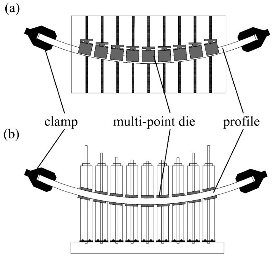
The forming principle of multi-point stretch-bending.
Material model
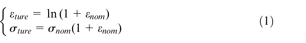
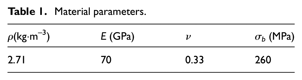
In this paper, the complex T-shaped profile are used for simulation analysis. The cross-section shape and size are shown in Figure 2. The material used is AA6082 aluminium alloy in T6 heat treatment state, whose main performance parameters are shown in Table 1. The total length of the profile is 6000 mm. The stress-strain curve obtained by single tensile experiments are shown in Figure 3. In order to accurately describe the stress-strain change of cross-section during large deformation, the input value required in the ABAQUS calculation process is real stress and real strain, and the conversion relationship between them is as follows:
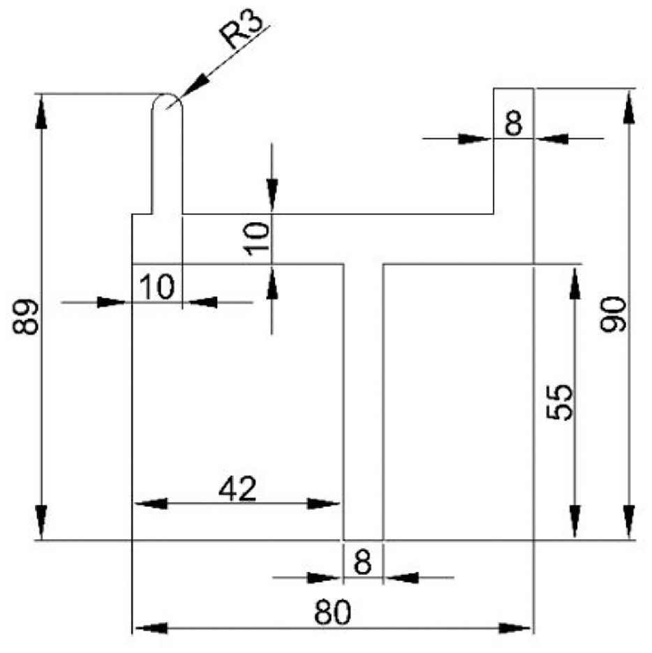
The cross-section shape and size.
Material parameters.
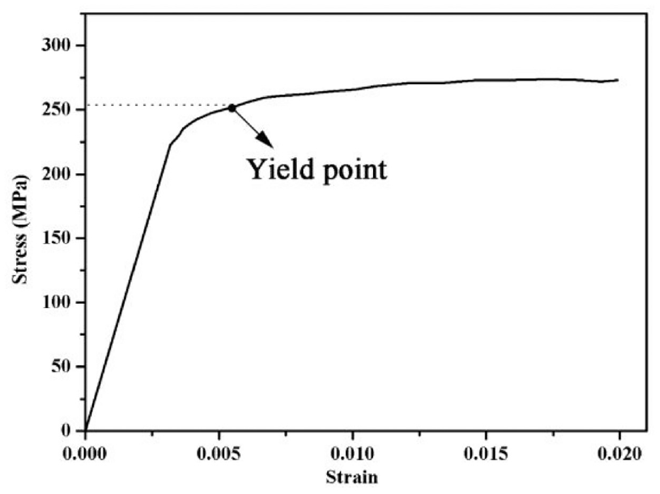
Stress-strain curve of the profile.
In the material model, it is assumed that the material is isotropic, and the constitutive relationship of the aluminium profile in the stretch-bending process is based on the elastic-plasticity mechanics theory and follows the Von Mises yield criterion and Prandtl-Reuss incremental theory.
Establishment of finite element model
In this paper, ABAQUS/explicit software is used to simulate the multi-point stretch-bending process. In the actual stretch-bending process, the profile is symmetrical about the length direction, and the clamps at both ends of the profile also operate symmetrically. Therefore, only 1/2 profile is established and analyzed in order to save the calculation time. Through the simplification of the model, the finite element model is mainly composed of clamp, profile and dies. Figure 4 is the main components and the assembly drawing of the finite element model. Firstly, the shape of the die and clamp are designed according to the shape of the profile, and then the number of the die is determined according to the length of the profile. In the stretch-bending process, the profile will deform, whose deformation is our research object. Therefore, the profile is selected as deformable body, and C3D8R is adopted as the mesh element, which is an 8-node hexahedral reduced integral solid element with a finer mesh division than the die and clamp. The stiffness of the clamp and die is much greater than that of the profile, and its deformation in the stretch-bending process are very small, which can be ignored. Therefore, in order to improve the simulation efficiency, the clamp and die select the discrete rigid body without deformation calculation, and R3D4 is adopted as the mesh element, which is a 4-node three-dimensional rigid quadrilateral with bilinear. When the model is assembled, firstly, the dies are arranged at equal intervals, and then the corresponding die are moved to the relative position according to the trajectory formula of the die, and the clamp and profile are tied. After assembly, Coulomb friction model is chosen to describe friction behaviour when defining interaction, and penalty function method is used for contact problem. Then, the boundary conditions are defined according to the actual working conditions. Finally, double precision is used to submit the job.
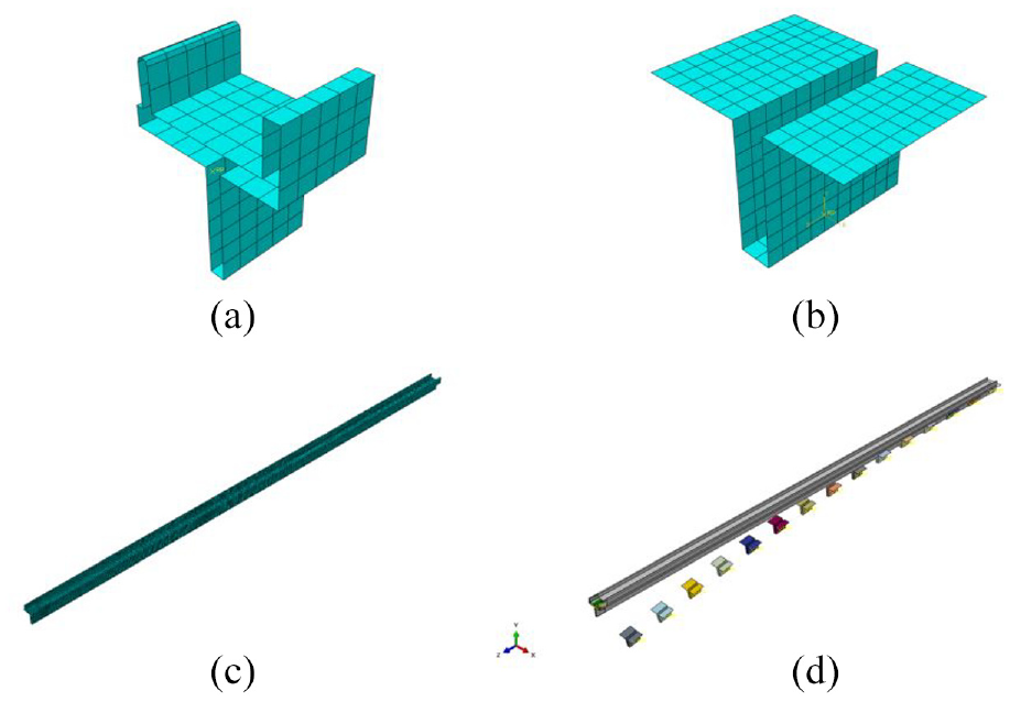
Main components of the model: (a) The clamp(b) The die (c) The profile and (d) Model assembly drawing.
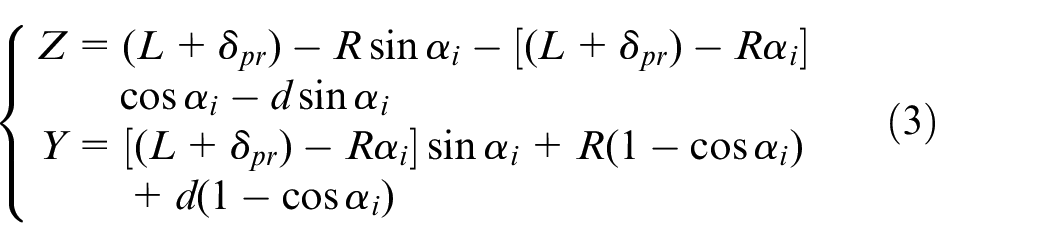
In the stretch-bending process, the bending of the profile depends on the movement of the clamp, so the determination of the clamp trajectory and position of the die is very important. In the numerical simulation, the amplitude curve is used to control the movement of the clamp. Figure 5 is the calculation diagram of the clamp reference point and the die track when profile bends. The trajectory of the die and the clamp is calculated as follows.
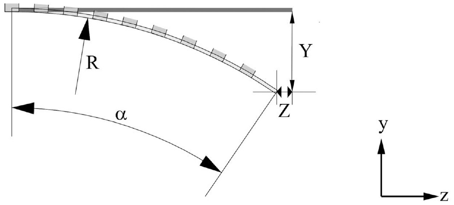
Calculation diagram of the trajectory of the clamp and the die.
During bending,
The position of the die:

The trajectory of the clamp:
During pro-stretching, the trajectory of the clamp:
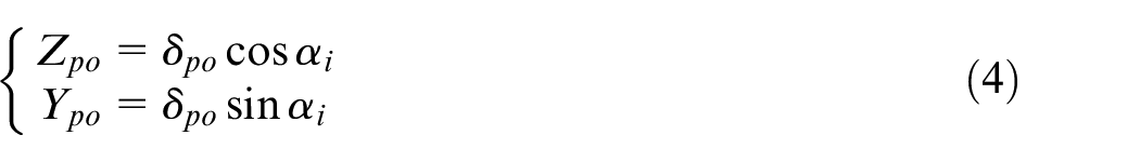
Where L is the original length of the profile, δpr and δpo are pre-stretching amount and pro-stretching amount respectively, Yi is the moving distance of the i-th die, R is the bending radius, αi is the angle at which the profile is fit with the i-th die during the bending process, ϕi is the rotation angle of the i-th die, Di is the distance from the i-th die to the first die, Z is the displacement of the clamp reference point along the Z axis, Y is the displacement of the clamp reference point along the Y axis, and D is the distance from the clamp reference point to the bottom of the profile. Zpo and Ypo is the displacement of the clamp reference point along Z-axis and Y-axis, respectively, during pro-stretching.
Research on section distortion of forming defect in multi-point stretch-bending
In the stretch-bending process, due to the tensile stress, the section distortion phenomenon will inevitably occur, including height shrinkage and width shrinkage, which will affect the forming quality of the part. The volume of the profile remains unchanged in the stretch-bending process. During pre-stretching stage, the profile is subjected to uniform forces. In the bending stage, the curvature of the profile starts to change due to the external bending moment, and the deformation of the profile is more complicated, so the axial direct stresses of nodes under different paths are analyzed at the end of bending, as shown in Figure 6(a). Paths a, b and c are in the outer part, the middle part, and the inner part of the bend, respectively. As the direction of direct stress is along the cross-sectional normal direction, the positive and negative values of direct stress have their physical meanings, where the positive value indicates tensile force, and the negative value indicates compressive stress. It can be seen that the nodal stress along path a is tensile stress, whose value fluctuates around the yield strength, indicating that the outer side of the profile bending is in a plastic tensile state; the nodal stress along path b is also tensile stress, but in the elastic deformation range. The nodal stress value in the middle of the profile along path c fluctuates around zero, but as it approaches the clamp, the stress at the node is compressive, indicating that the inner side of the profile near the clamp is in compression. According to the stresses in the section, the section after bending can be divided into plastic tensile zone, elastic zone and plastic compression zone. In order to more clearly illustrate the stress state during stretch-bending process, the stress cloud diagram of the cross-section near the clamp along the Z-axis is selected from the simulation results, as shown in Figure 6(b), and the colour change of the cross-section at each stage more intuitively describes the stress situation of the profile.
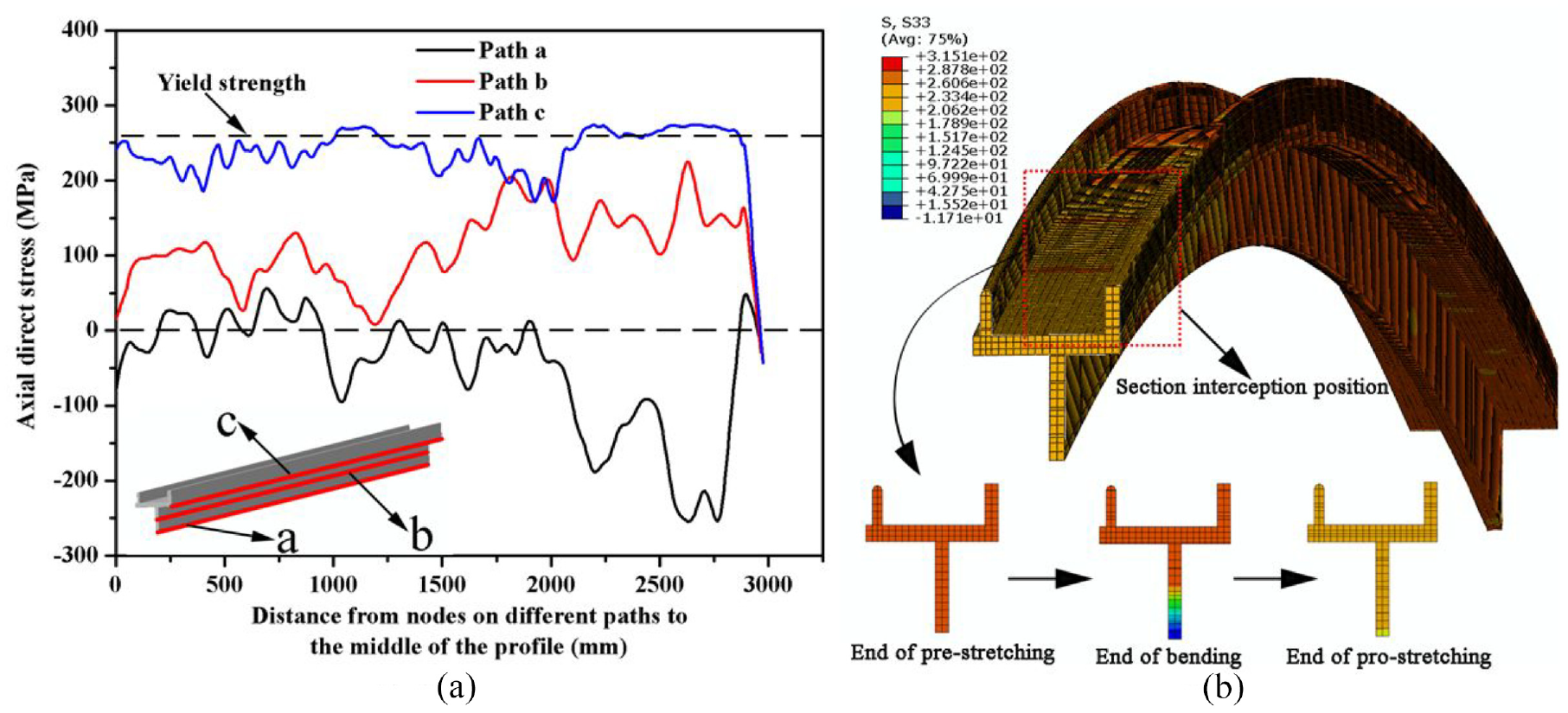
Direct stress distribution of nodes under different paths: (a) The axial direct stresses of nodes under different paths. (b) the change of cross-section at each stage.
Based on the above analysis, a physical analysis of the stretch-bending forming of the profile was carried out. At different stages of the forming process, the change of stress with strain on the inside and outside of the bend and the distribution of stress in the cross-section are different, as shown in Figure 7. When pre-stretching, the profile is generally considered to be stretched above the yield point, that is, point b. The path of change of stress with strain is o-a-b, when the stress distribution in the cross-section is uniform and the stress change is σpre.

In bending, the stress-strain in the cross-section is changed by the bending moment M. The outer fibres by the additional tensile effect along the straight line ab in Figure 7(a) loaded, the stress change for σw′, while the inner fibres along the straight line bc elastic unloading, the stress change for σn′. σn′ from small to large can cause the inner fibres elastic stretch, elastic compression and plastic compression in turn, the stress-strain relationship can be expressed as follows:
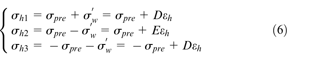
where σh1, σh2 and σh3 are the stresses in the plastic tensile, elastic and plastic compressive zones respectively, εh is the neutral layer strain, and D is the plastic modulus.
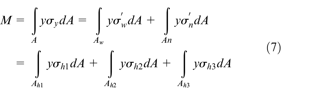
The external added bending moments is:
During the pro-stretching stage, all fibres will theoretically elongate uniformly, resulting in a redistribution of stress-strain in the cross-section. Fibres previously in plastic tension will be further subjected to plastic tension, fibres in elastic tension and compression will be reloaded along the linear cb, while fibres in plastic compression will change along the red dashed line in Figure 7(a), with the stress change across the cross-section during the replenishment phase shown as the red dashed line in Figure 7(b).
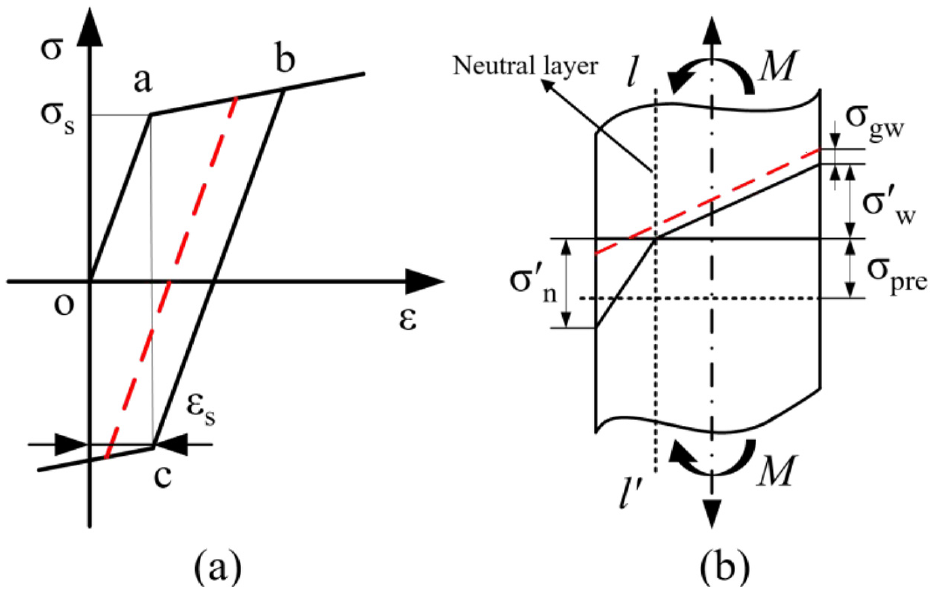
Schematic diagram the different stages of profile stretch-bending. (a) Variation of stress with strain at different stages. (b) Stress distribution in the section at different stages.
The presence of tensile and compressive stresses can have a large effect on the variation of the height and width of the section. Figure 8 shows the deformation of the cross-section after forming. In the pre-stretching stage, the profile is uniformly elongated under tensile stress, resulting in a reduction of the web height and panel width. During the bending stage, in the plastic stretching zone, a part of the panel and the web is subjected to a large tensile stress, and the height of a part of the web and the width of the panel are further reduced; in the elastic zone, a part of the web area is in an elastic state, so its height does not change after unloading after forming; in the plastic compression zone, if the compressive stress generated by the bending moment is much larger than the tensile stress in the pre-stretching process, the bottom area of the web will be compressed and destabilized, and its height will increase to a certain extent, but the degree of increase is much smaller than the degree of reduction in the part of the web in the plastic stretching zone, so the web height as a whole shows a reduction phenomenon. The pro- stretching after bending causes the overall tensile stress on the profile, which further reduces the panel width and web height. The change in panel width is denoted as
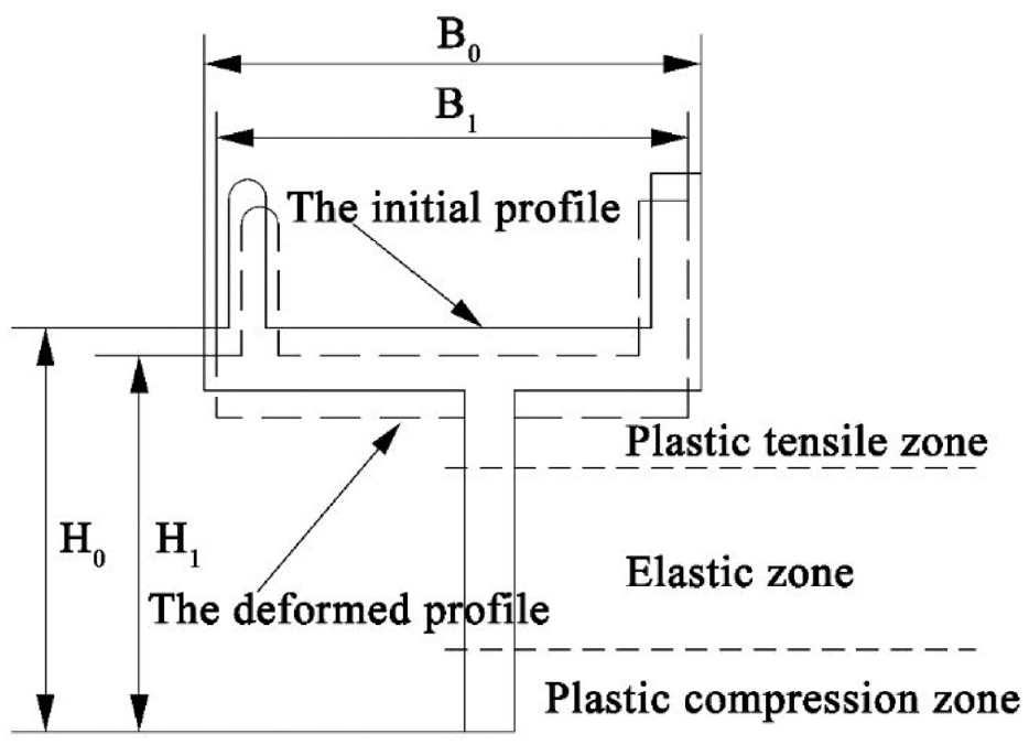
The deformation of the section after forming.
Numerical simulation results and discussion
Influence of bending radius on section distortion
In the stretch-bending, the bending radius is not only an important process parameter, but also an important design parameter, which basically represents the degree of deformation and will often play a key role in the forming results. 20 Thus, the section distortion under different bending radius is studied under the condition that the pre-stretching is 1%, the pro-stretching is 1%, and the friction coefficient is 0.15.
Figures 9 and 10 are Mises stress clouds and equivalent plastic strain clouds for different bending radius. The numerical results show that the maximum Mises stress is 335.4 MPa, 313.7 MPa, 306.9 MPa, 299.5 MPa and 297.1 MPa, respectively and the maximum equivalent plastic strain is 0.1206, 0.0765, 0.05908, 0.04938 and 0.04527 when the bending radius is 8000 mm, 10,000 mm, 12,000 mm, 1,40,000 mm and 16,000 mm. The larger the bending radius is, the smaller the deformation is, the smaller the maximum equivalent stress and the maximum equivalent strain are, and the distribution of stress and strain is more uniform. Moreover, the stress and strain in the contact area between the profile and the die is greater than that in the non-contact area, which is mainly caused by the constraint of the die on the profile. In addition, as the die is designed as a straight line, the profile cannot fit the dies well, so it is easy to produce stress concentration in the contact area between the die edge and the profile, and larger stress concentration may form some defects such as creases.
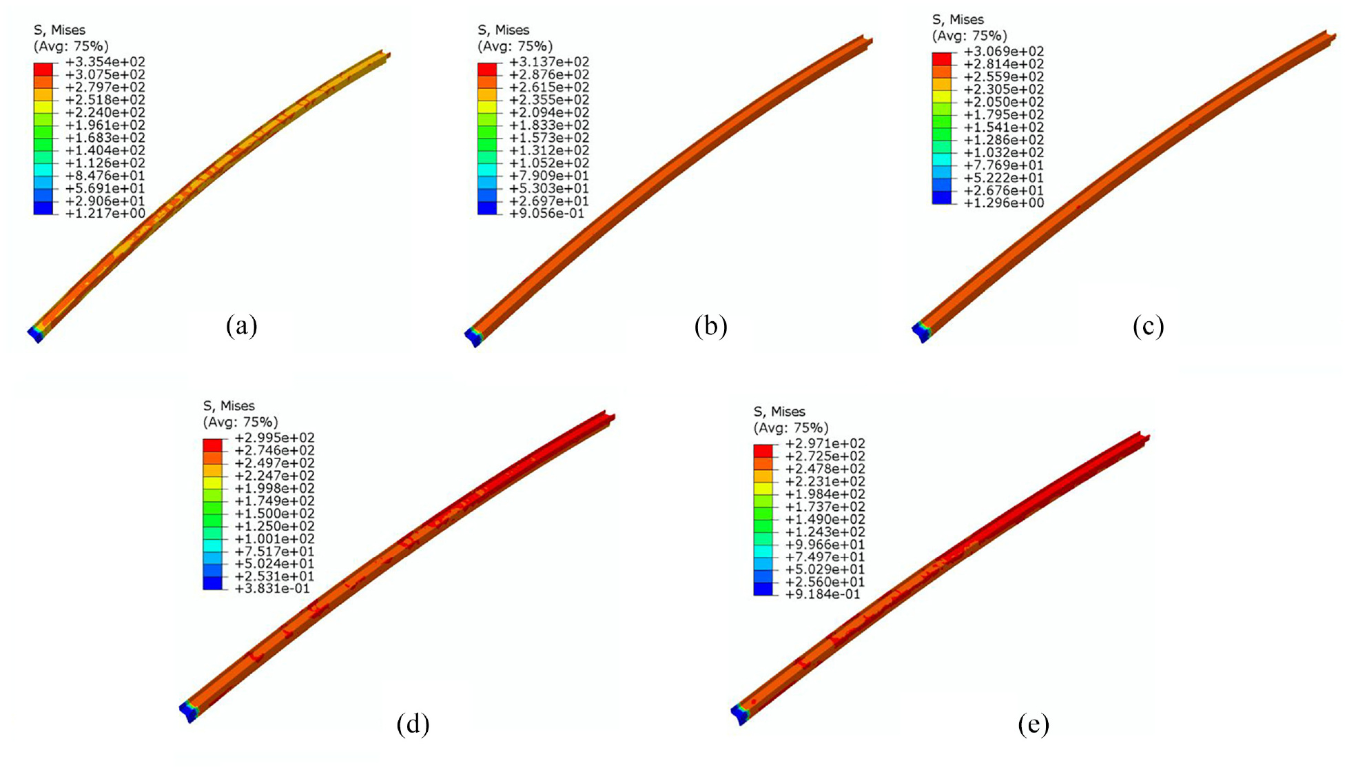
Mises stress clouds under different bending radius. (a) R = 8000 mm (b) R = 10,000 mm (c) R = 12,000 mm(d) R = 14,000 mm and (e) R = 16,000 mm.
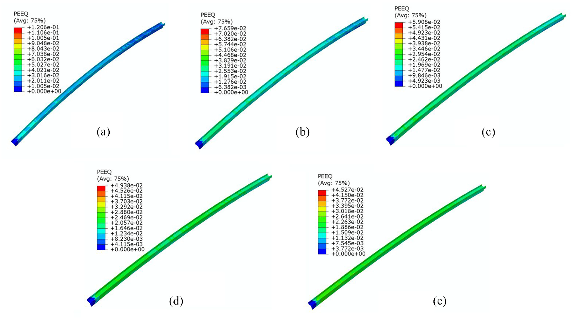
Equivalent plastic strain clouds under different bending radius. (a) R = 8000 mm. (b) R = 10000 mm. (c) R = 12,000 mm. (d) R = 14,000 mm and (e) R = 16,000 mm.
Figure 11 shows the distribution of section shrinkage values under different bending radius. The numerical simulation results show that the smaller the bending radius is, the larger the curve fluctuation is, the more serious the section distortion is, and the worse the forming quality is. Mainly the smaller the bending radius, the greater the additional tension on the outside of the bend and the greater the compressive stress on the inside of the bend. When R = 16,000 mm,
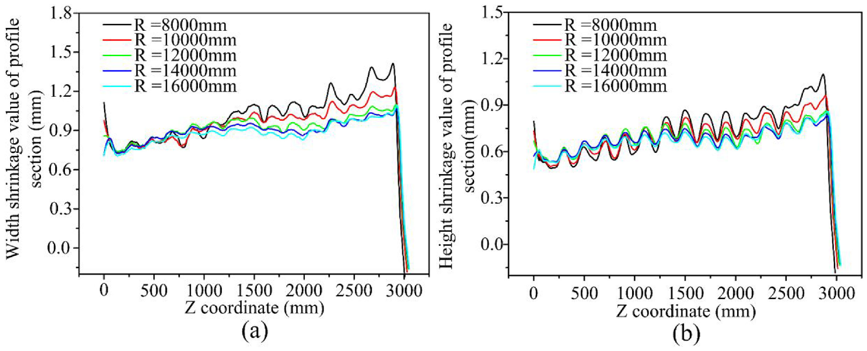
The distribution of section shrinkage values under different bending radius. (a) Width shrinkage (b) Height shrinkage.
Influence of pre-stretching amount on section distortion
In this section, the section distortion under different pre-stretching amount of 0.3%, 0.6%, 0.9% and 1.2% is studied under the condition that the pro-stretching is 1%, and the friction coefficient is 0.15. Figure 12 is the variation diagram of section distortion of different pre-stretching under different bending radius. The numerical simulation results show that the section shrinkage decreases with the increase of bending radius, and increases with the increase of pre-stretching amount. The maximum width shrinkage value vary from 0.78 mm to 1.46 mm, and the maximum height shrinkage value vary from 0.61 mm to 1.07 mm. The larger pre-stretching amount, the greater the tangential tensile stress to which the profile is subjected, and the greater the elongation of the profile when the volume remains unchanged.
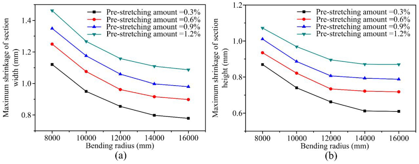
The maximum section shrinkage value under different pre-stretching under different bending radius (a) Width(b) Height.
Influence of pro-stretching amount on section distortion
In this section, the section distortion under different pro-stretching amount of 0.3%, 0.6%, 0.9% and 1.2% is studied under the condition that the pre-stretching is 1%, and the friction coefficient is 0.15.
Figure 13 is the variation diagram of section distortion of different pro-stretching under different bending radius. The numerical simulation results show that the change trend of section shrinkage with the increase of bending radius remains basically the same when pro-stretching is from 0.3% to 0.9%. But when pro-stretching is 1.2%, the overall increase trend of section shrinkage is obvious, especially when R exceeds 12,000 mm, the curve is relatively straight, and the influence of bending radius on section shrinkage is no longer obvious. The reason is that pro-stretching amount of has a great influence on the deformation under the smaller bending radius, but when R is large, the bending amplitude of the profile changes less obviously, so pro-stretching has no obvious influence on the section shrinkage value under the larger bending radius. The larger the pro-stretching, the more serious the section distortion, the worse the forming quality. Therefore, in the case of reducing the springback by applying pro-stretching, a smaller amount of pro-stretching should be used as much as possible to obtain a better forming quality.

The maximum section shrinkage value of different pro-stretching under different bending radius. (a) Width (b) Height.
Influence of friction coefficient on section distortion
In this section, the section distortion under different friction coefficient of 0.05, 0.10, 0.15 and 0.20 is studied under the condition that the pre-stretching is 1%, and the pro-stretching is 1%. Figure 14 is the variation diagram of section distortion of different friction coefficient under different bending radius. Numerical simulation results show that the shrinkage of section width and height both increased with the increase of friction coefficient. The larger the friction coefficient is, the worse the flow ability of the profile is, and the more likely to aggravate the difference between the fluidity of the profile in contact with the die and the fluidity of the suspended part of the profile, making the elongation of profile at the suspended part larger. When the friction coefficient is 0.05, the section shrinkage is the least. Hence, in the actual production, the forming quality can be improved by applying lubricant.
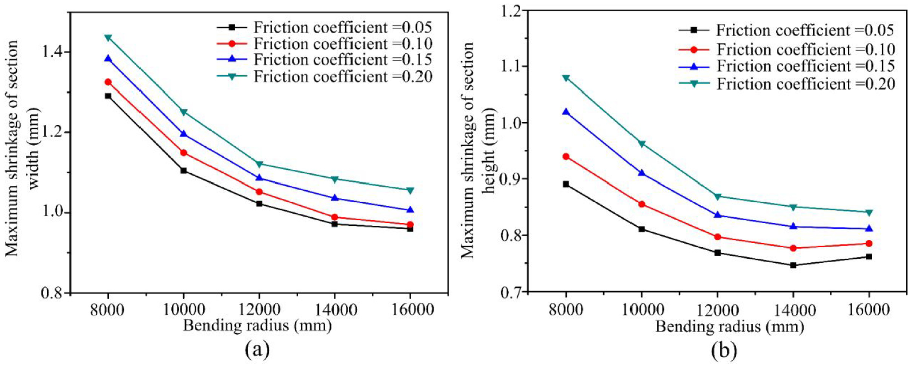
The maximum section shrinkage value of different friction coefficient under different bending radius. (a) Width(b) Height.
Multi-point stretch-bending forming experiment
In order to verify the accuracy of the simulation results, corresponding experiments were carried out in this paper. The aluminium profile component of the front frame of high-speed railway with a length of 6000 mm was used for multi-point bending experiments on a multi-point bending machine. Figure 15(a) is the multi-point stretch-bending process. In order to verify whether the forming rule is consistent with the simulation results, the NDI large-space measuring instrument PROCMM3500 optical tracker is used to scan the formed part, as shown in Figure 15(b). For the experiments, the positions of the contact zone between the die and the profile and the non-contact zone were selected for the measurement of the section width and height, and the same positions were also chosen for the simulation. The comparison shows that the trend of the simulated and experimental results is basically the same and that the maximum section distortion is at the overhang of the profile in the last die and the penultimate die, which is also consistent with the results of the above analysis, as shown in Figure 16. At the same time, through comparison, it is found that the experimental results and the simulation results of the maximum section shrinkage value under different bending radius, pre-stretching amount, pro-stretching amount and friction coefficient are basically consistent, which verifies the validity of the simulation, as shown in Figure 17.
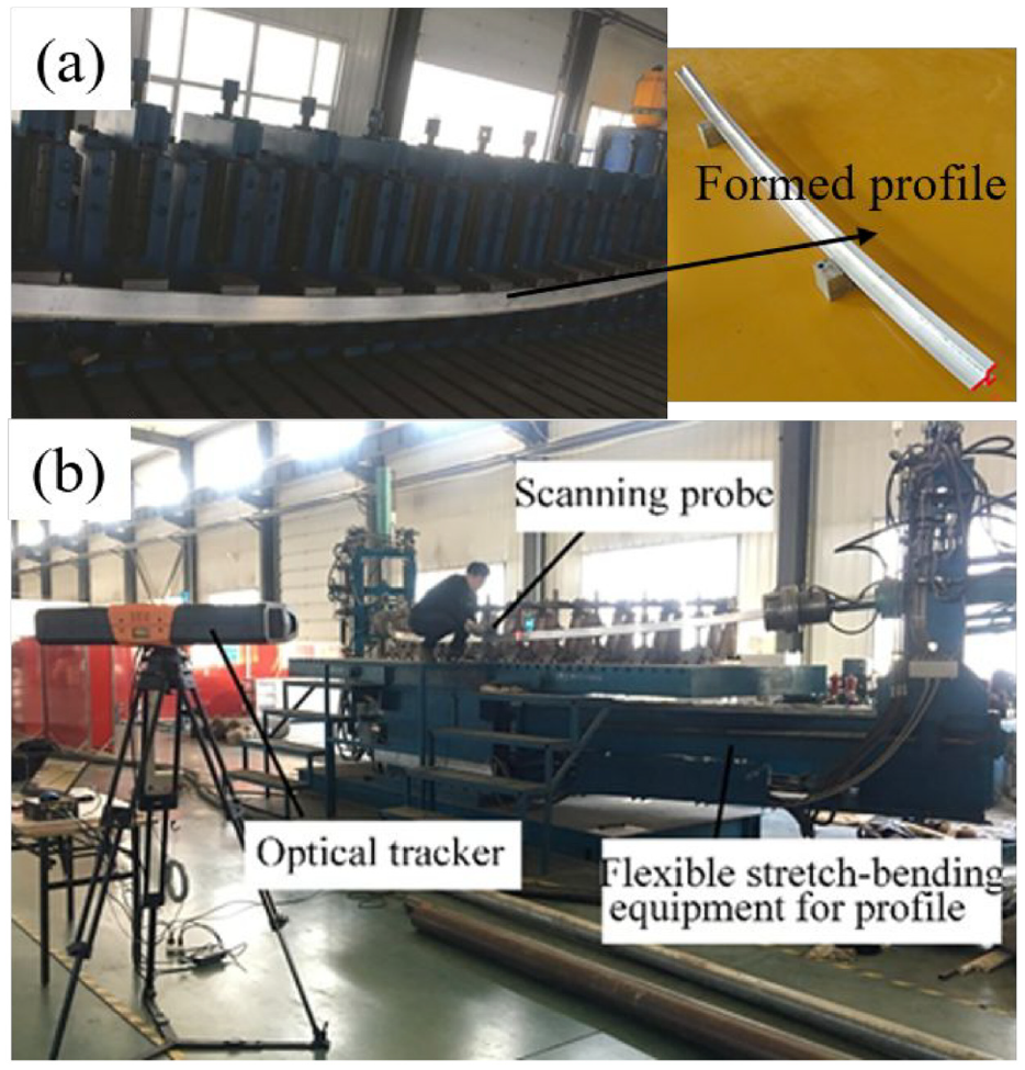
(a) Multi-point stretch-bending process (b) 3D scanning equipment to measure the deformation of the part.
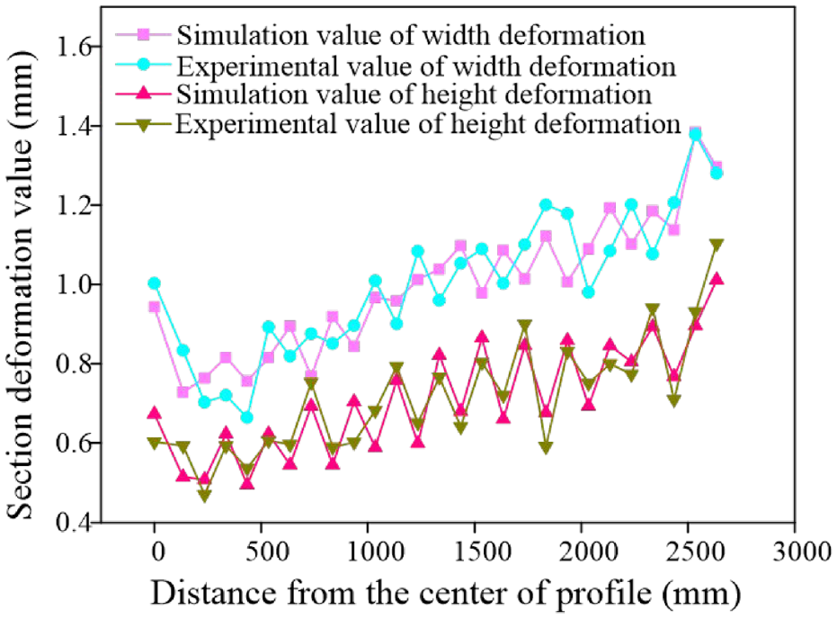
Comparison of experimental and simulation results for section deformation.
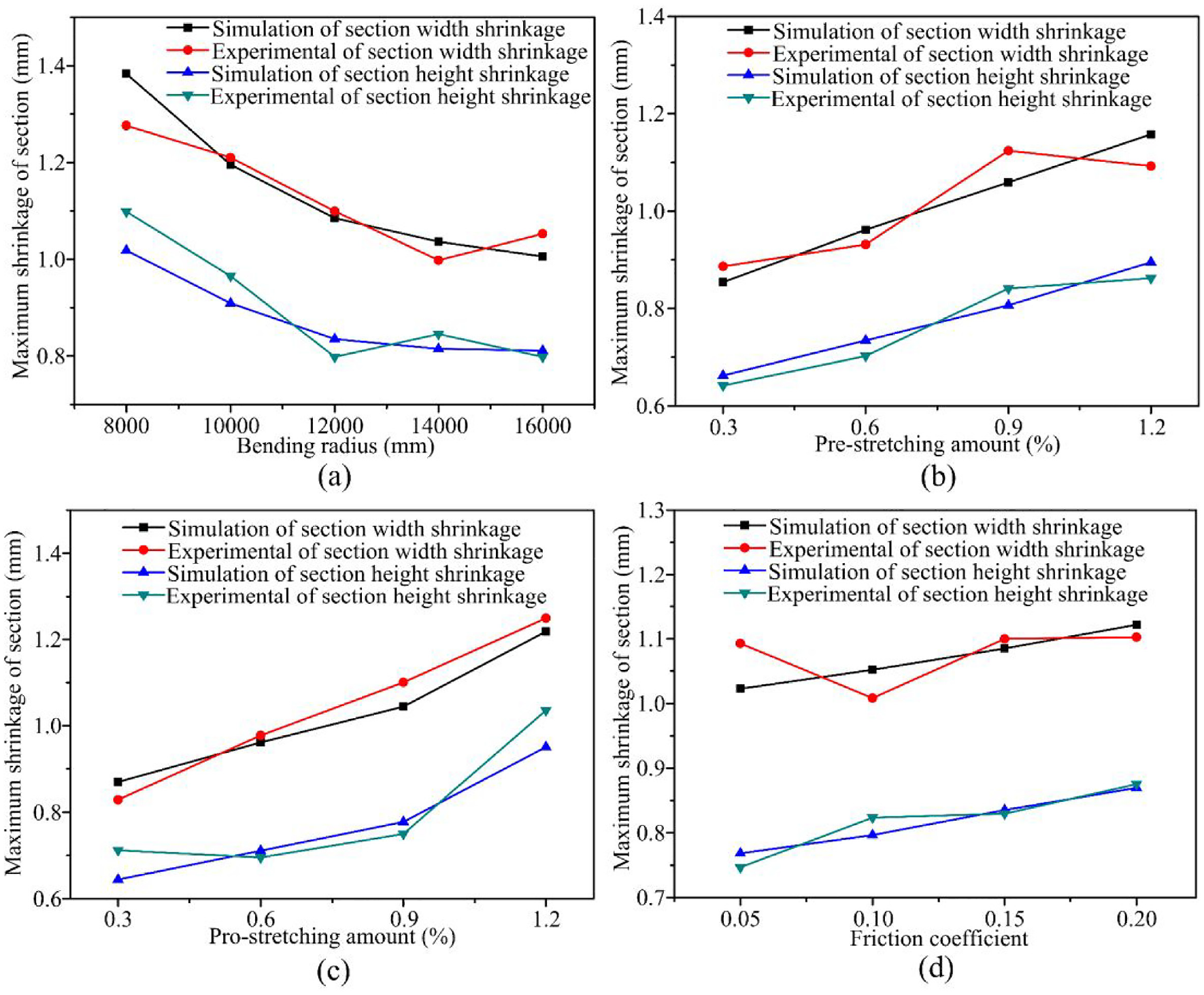
The maximum section shrinkage value of section width and height under different processing parameters. (a) Bending radius (b) Pre-stretching (c) Pro-stretching and (d) Friction coefficient.
Control of cross-section distortion
In the previous section, the influences of different processing parameters on section distortion have been studied. It can be seen that for different pre-stretching amount, pro-stretching amount and friction coefficient, the section shrinkage decreases with the increasing bending radius. Thus the relationship between the maximum section shrinkage δ and bending radius R can be expressed by formula (8):
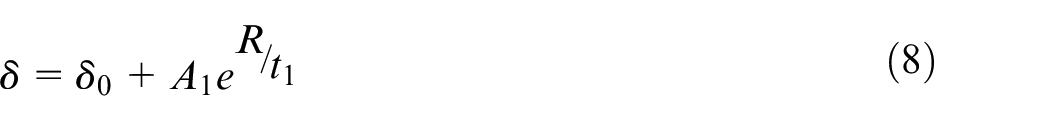
Where, unknown parameters
In the case of demanding high dimensional accuracy, section deformation is an important factor in determining forming accuracy. In actual production practice, the defects generated during profile processing and forming cannot affect the use (i.e., the defects are within the tolerance of the manufacturing of the parts). According to the actual use requirements of the aluminium headstock components of high-speed trains, the section width shrinkage and the section height shrinkage need to be controlled below 1 mm and 0.9 mm respectively. Based on the above study, the minimum bending radius for different process parameters without section distortion exceeding a given value is explored here, as shown in Figure 18(a)–(c). It can be seen from the figure that with the increase of pre-stretching amount, pro-stretching amount and friction coefficient, the minimum bending radius of the aluminium profile without section distortion that affects the use shows different degrees of increasing trend, that is the pre-stretching amount is 0.3%, the pro-stretching amount is 0.3% and the friction coefficient is 0.05, the bending radius of the profile is the smallest. It is mainly the increasing of pre-stretching amount and pro-stretching amount that leads to increased tangential stress, greater elongation deformation and increased section deformation. Regarding the minimum bending radius of the section width, it can be seen that there is no minimum bending radius when the pre-stretching amount is 1.2%, the pro-stretching amount is 1.2%, and the friction coefficient is 0.2, mainly due to the fact that the section distortion is so serious in the case of using these process parameter values that the improvement is almost negligible even if the bending radius is reduced. As for the shrinkage of the section height, there is no minimum bending radius only when the amount of pro-stretching amount is 1.2%, indicating that the pro-stretching amount has a more significant influence on the shrinkage of the section height. The quality control curves on section distortion can provide some reference for the actual processing boundaries. In the actual production process, suitable processing parameters can be selected for forming, which will greatly reduce the scrap rate of the parts.
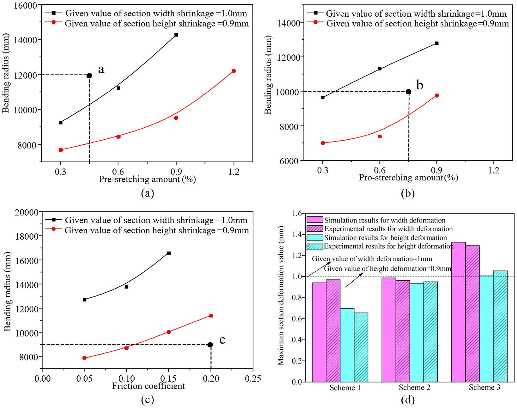
Minimum bending radius for different process parameters. (a) Pre-stretching amount (b) Pro-stretching amount(c) Fiction coefficient and (d) Section deformation for different schemes.
In order to verify the accuracy of the above section deformation processing boundary diagram, the parameters of points a, b and c in Figure 18 were extracted for the corresponding simulations and experiments, which were noted as Scheme 1, Scheme 2 and Scheme 3, respectively. The simulation and experimental results are shown in Figure 18(d). It can be seen from the figure that although there are errors between the simulation and experimental section deformations, the maximum error in section width is 3.12% and the maximum error in section height is 6.15%, which is within the acceptable range. According to the prediction of the processing boundary diagram, the section deformation of option 1 should meet the requirements, the section width deformation of option 2 should meet the requirements, while the section height deformation will exceed the given value, and the section deformation of option 3 will not be within the requirements. The simulation and experimental results of all three scheme are consistent with the predictions of the processing boundary diagrams, indicating that the processing boundary diagrams obtained for section deformation are of some reference significance for actual production practice.
The proposed quality control curve on section distortion in this paper, on the one hand, the choice of stretch-bending process parameters can be guided when product quality is the constraint, in order to reduce trial and error costs, shorten the cycle time, obtain qualified parts, thus achieving mass production of structural parts for the headstock of high-speed trains, as shown in Figure 19. On the other hand, this paper on the establishment of quality control curves is not limited to section deformation, but can be extended to other forming defects, such as springback, thinning, shape deviation, etc. It is also applicable to establish quality control curves under other influencing factors, such as structural dimensions, material variables, etc.
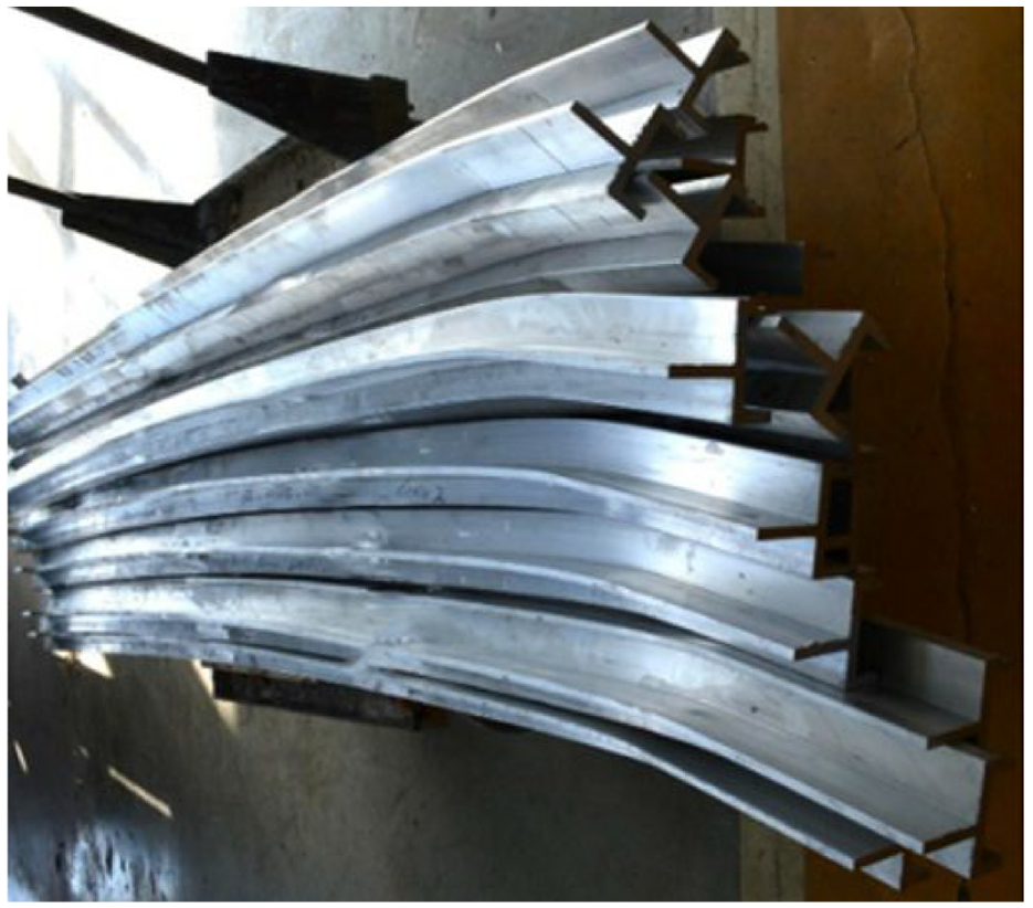
Mass production of profiles.
Conclusions
In order to gain a more comprehensive understanding of the section deformation pattern in multi-point stretch-bending, the influences of different processing parameters such as bending radius, pre-stretching amount, pro-stretching amount and friction coefficient on the section deformation are investigated through a combination of numerical simulations and experiments, and on the basis of this, the processing boundary diagrams of the section deformation is established in a simpler way to guide the mass production of the profile. The main conclusions are as follows.
During multi-point stretch-bending, the outer side of the bend is subjected to tensile stress and the inner side of the bend to compressive stress, which is the main cause of the section deformation of the profile. The maximum section deformation occurs in the overhang of the profile between the last die and the penultimate die.
Different process parameters have a definite effect on section deformation. The section deformation decreases with increasing bending radius and increases with increasing pre-stretching amount, pro-stretching amount and friction coefficient. The relationship between section deformation and bending radius can be expressed as an exponential relationship of decay for different process parameters.
The minimum bending radius increases with the pre-stretching amount, pro-stretching amount and the friction coefficient. At a pre-stretching amount of 0.3%, pro-stretching amount of 0.3% and a friction coefficient of 0.05, the minimum bending radius is smallest and the profile has the best formability.
Several multi-point bending experiments were carried out on aluminium profiles. The experimental results and the simulation results basically match each other, verifying the validity of the model. At the same time, the reliability of the established processing boundary diagrams of cross-sectional deformation has been demonstrated by means of corresponding simulations and experiments. For this reason, the numerical simulations allow the optimisation of the machining parameters and thus guide the actual production practice and cost savings.
Footnotes
Authors’ contributions
Yi Li, and Jicai Liang developed the idea of the study, Chenyang Lv, and Ce Liang participated in its design and coordination and helped to draft the manuscript. Yi Li, and Chenyang Lv contributed to the acquisition and interpretation of data. Ce Liang provided critical review and substantially revised the manuscript. All authors read and approved the final manuscript.
Declaration of conflicting interests
The author(s) declared no potential conflicts of interest with respect to the research, authorship, and/or publication of this article.
Funding
The author(s) disclosed receipt of the following financial support for the research, authorship, and/or publication of this article: This work was financially supported by the Project of Jilin Provincial Scientific and Technological Department (20190302037GX); the China Postdoctoral Science Foundation (2017M611321).
Availability of data and material
The datasets used or analysed during the current study are available from the corresponding author on reasonable request.
Code availability
Not applicable.