
Abstract
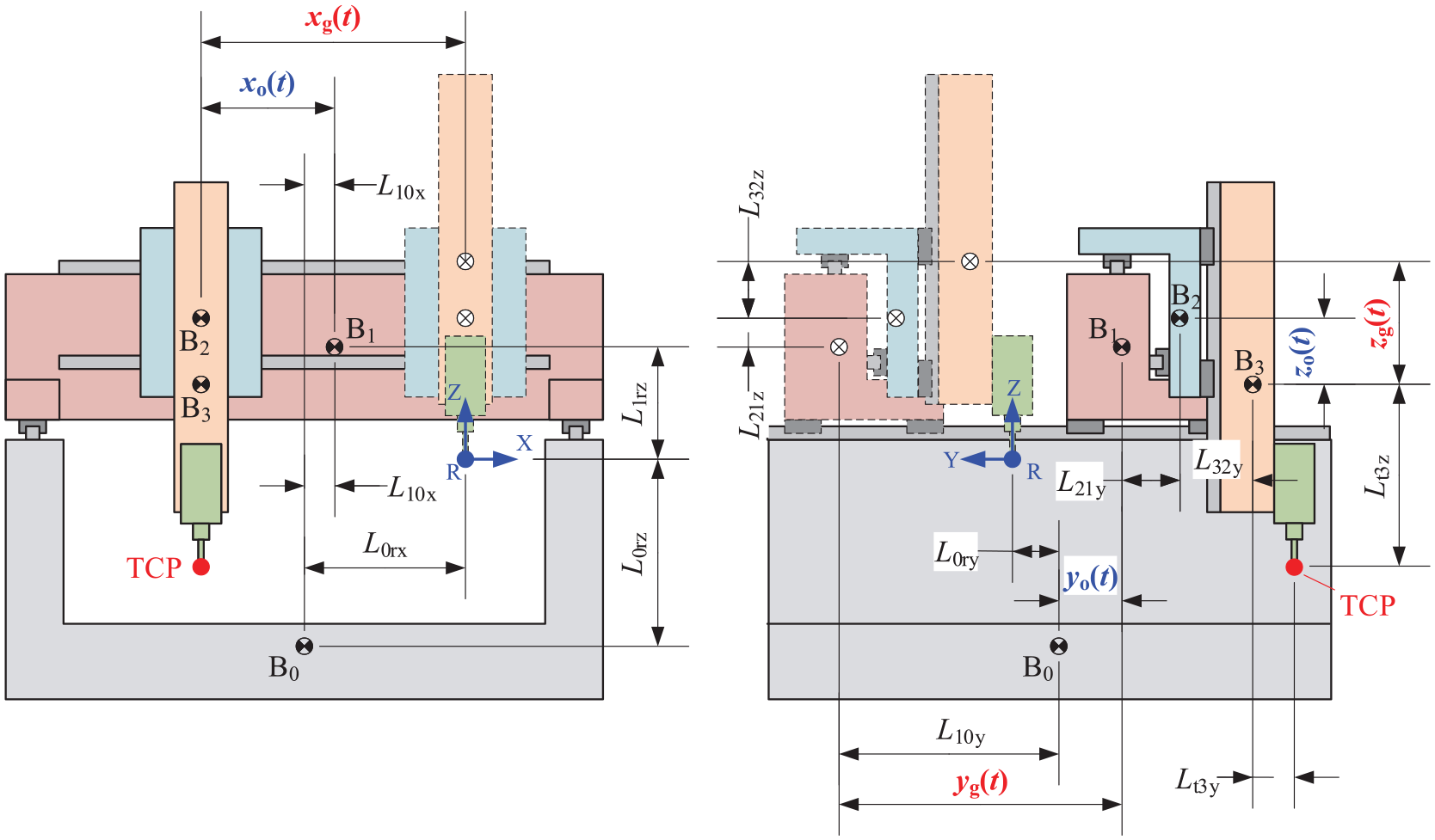
During the working process of high-speed multiaxis machine tools, inertial forces can cause vibration and deformation of mechanical structure, which lead to the dynamic error of tool center point (TCP) relative to worktable and can adversely affect the machining performance. Considering the varying feed positions and accelerations during machining, a parameter-varying multi-rigid-body dynamic model of a 3-axis gantry machine tool is proposed. This model represents the position dependent structural dynamics and inertial forces, which can simulate the dynamic error of TCP relative to worktable within the entire workspace. The results show that the dynamic error in one direction is affected by the feed motions of multiple feed axes. The magnitudes of the dynamic error significantly vary with the position of Z-axis. And the dynamic errors in Y- and Z-direction show different varying trends. Then the theoretical model is used to discuss the dynamic error and position dependency. The expressions of TCP dynamic response and inertial forces reveal the reason why the dynamic errors in Y- and Z-direction show different varying trends.
Introduction
The increasing feed accelerations of feed axes enhance the inertial forces effect during working process of high-speed machine tools. The inertial forces can cause vibration and deformation of mechanical structure, which lead to dynamic error of TCP relative to worktable (DETW).1,2 For multi-axis machine tools with kinematic coupling, axis coupling effect brings the coupling forces among multiple axes and varying structural dynamics.3–6 These effects result in the complex characteristics of DETW during feed motions, which make the analysis and control of dynamic error of high-speed multiaxis machine tools more challenging.
The dynamic error induced by inertial forces during accelerating and decelerating stage has received great interest in the process of design and analysis of high-speed and high precision machine tools. In recent years, the related content has been added in international standards. Slocum, 7 Heisel and Gringel, 8 and Reinhart and Weissenberger 9 indicated that inertial forces can cause vibration and deformation of mechanical structure. Brecher et al. 10 defined the distance of the gravity center to the incidence point of drive force as Steiner Distance which is one of the crucial factors that influence acceleration forces induced error. This kind of error was considered as an important error source when designing high precision machine tools. Bringmann and Maglie, 11 Nguyen et al., 12 and Thoma et al. 13 proposed in-talk and cross-talk concepts to describe the dynamic deviation at TCP of machine tools with inertial effect. And Inertial Cross-Talk was presented in ISO 230-8:2009 to evaluate the vibrations of machine tools during accelerations and decelerations.
The dynamic error cannot be directly measured by rotary encoder and linear encoder,14,15 which result in that the traditional feedback controller is incapable of controlling DETW. Therefore, it is necessary to develop a theoretical model which can estimate DETW. Parenti et al. 16 analyzed the effect of inertial deformation on machine tool accuracy by using finite element model. A simplified single degree of freedom (DOF) model was used to design a feed-forward compensation filter. Matsubara et al. 17 and Nagaoka and Matsubara 18 developed a transfer function model of machine tool structure using modal superposition method. A model-reference feed-forward controller was designed to control the load position of machine tool axes. Altintas and Khoshdarregi 19 characterized the structural dynamic mode of feed drive by using a second order transfer function model. The integrated vibration avoidance and contouring error compensation is developed using input shaping filter and pre-compensation. Uhlmann et al. 20 presented a reduced finite element model of machine tool structure. Denkena et al. 21 built a multi-rigid-body model of 2-axis feed system. They both proposed a Kalman filter containing the model of mechanical structure to estimate the dynamic dislocation and velocity of TCP. The Kalman filter was applied in the cascaded control of machine tool feed axes. Ansoategui et al.22,23 characterized the dynamics of feed drive and structure using 3-DOF lumped model. This model was used to estimate the maximum jerk of feed axes. Huang et al. 24 constructed a 4-DOF dynamic model of a single axis feed drive system to predict the tracking error and the elastic deformation. This model included the flexibility of the transmission and the machine bed. However, all the theoretical models in the above researches are linear time invariant (LTI) model. This kind of model cannot correctly represent the varying structural dynamics and inertial forces under axis coupling effect.
In recent years, the researchers have taken the axis coupling effect seriously for the demands of high-speed and high precision machining. The coupling forces were considered in the dynamic analysis of multiaxis machine tools, including inertial force,4,5 gravity force, 6 and friction force.3,25 In high-speed working condition, the inertial force effect is dominant because of the high acceleration. Many researchers have focused on the position dependent dynamics of multi-axis machine tool structure,26–29 including linear axis 30 and rotary axis. 31 These researches showed that the multiaxis configuration varies with the feed positions. The changing configuration leads to the redistribution of the structural inertia, which causes the variations of structural dynamics and inertial forces. In order to deal with the effect of the varying dynamics and inertial forces, Hiramoto et al. 32 proposed drive at the center of gravity principle to reduce inertial vibration. The changing center of gravity induced by feed motion was considered. Steinlin et al. 33 built a proportional model of cross-talk error and developed off-line compensation. The model was derived by linear fit of measured data. The proportion factor of the model was acceleration dependent and position dependent. In summary, limited open literature to date has reported modeling and discussion of DETW and its variation with feed positions. The existing models are too simple to characterize the structural dynamics and axis coupling inertial forces of a multiaxis machine tool. Therefore, it is necessary to develop a new theoretical model to study DETW and its position dependency. Detailed discussion of the position dependency of DETW is beneficial for the design and control of the dynamic error of high-speed multiaxis machine tools.
In this paper, a vertical gantry milling machine which is a typical 3-linear-axis machine tool with kinematic coupling is studied. Considering the varying feed positions and feed accelerations, the theoretical model is parameter-varying multi-rigid-body dynamic model. Dynamic response at TCP in the orthogonal direction of the feed direction is used to evaluate the DETW during accelerating stage. The variation of DETW with the feed positions is analyzed. By using the theoretical model, the effect of structural dynamics on the dynamic error and the mechanism of the position dependency of the dynamic error are discussed.
Dynamic modeling and solution process
Parameter-varying dynamic model considering the variation of feed positions
A gantry-type vertical milling machine which is a typical 3-linear-axis structure with kinematic coupling is studied. The equivalent dynamic model of the machine tool structure is multi-rigid-body model
34
as shown in Figure 1. The structural components are considered as rigid bodies. The machine tool structure is composed of four rigid bodies. The machine bed is written as
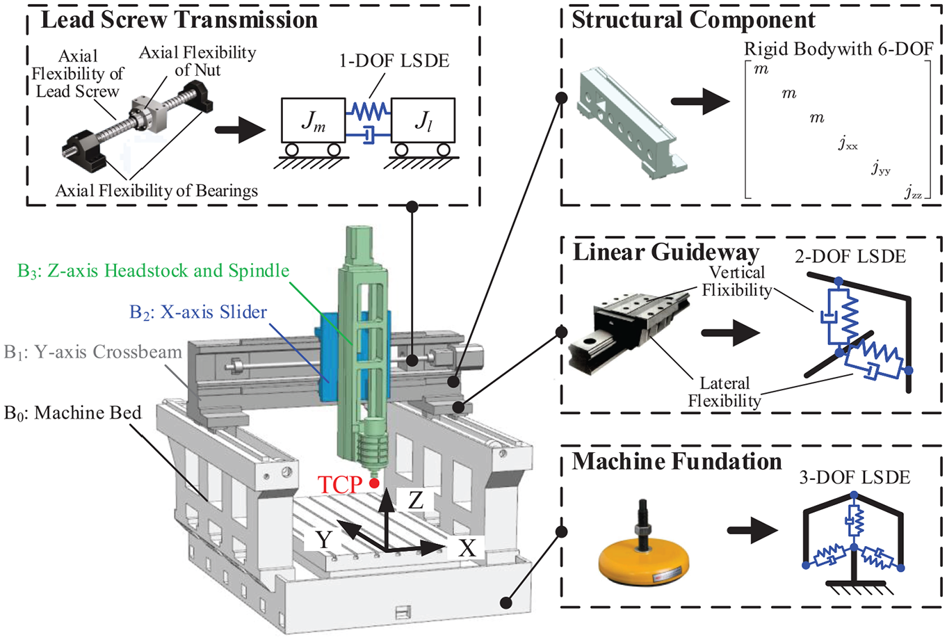
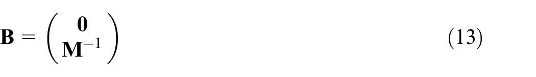
Equivalent dynamic model of machine tool structure.
The geometric parameters and feed motions of the machine tool are shown in Figure 2. Let the origin of the global reference frame RXYZ be located in the TCP position when all feed axes are at reference position.
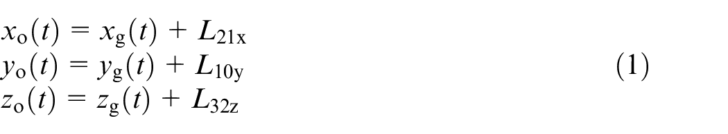
Geometric parameters and feed motions of the machine tool.
The structural components is modeled as rigid body with spatial 6-DOF. The DOFs of a structural component are given by:

where
The structure of the machine tool is typically treelike multi-body structure. Using the relative coordinate system, the DOFs
The

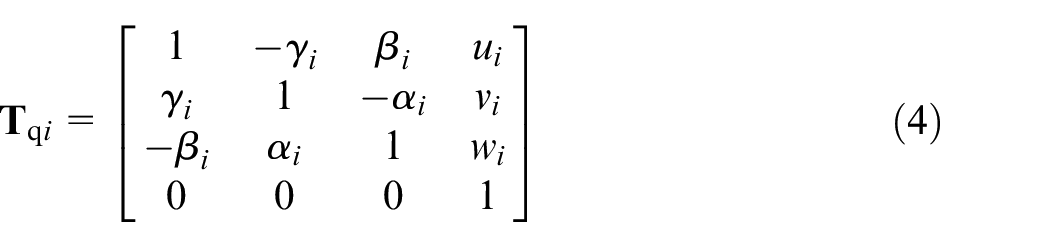
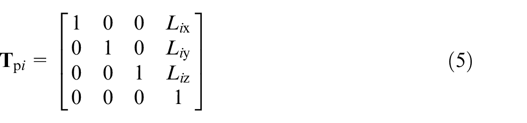
The transformation matrix of rigid body

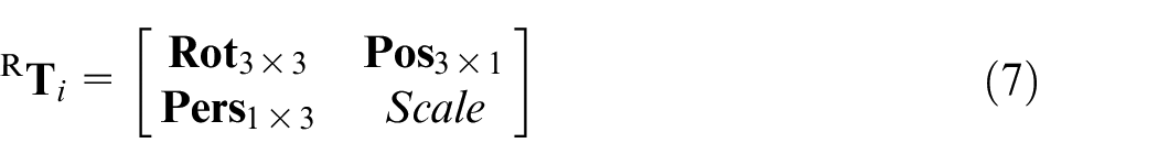
where
The deformations of LSDE can be derived by the position vector of the LSDE relative to the COG of structural components and the DOFs of structural components using homogeneous transformation. The position vector of LSDE relative to the COG of structural components is
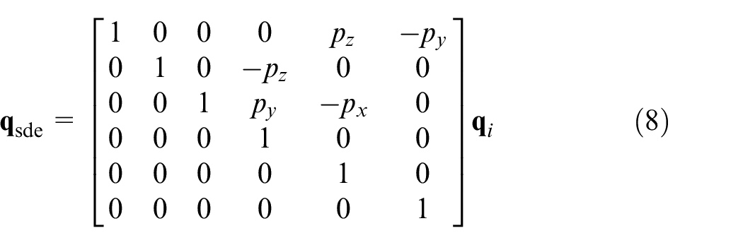
Therefore, the deformation of the LSDE can be given by:
The movements of all rigid bodies and the deformations of all LSDE have been derived. The kinetic energy
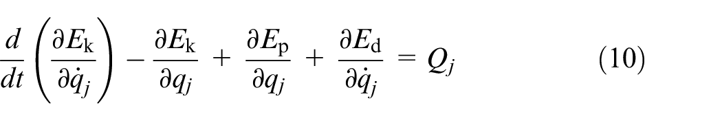
here j is the number of the generalized coordinates.
The dynamic stiffening terms in the dynamic equations are neglected. The terms corresponding to the feed accelerations
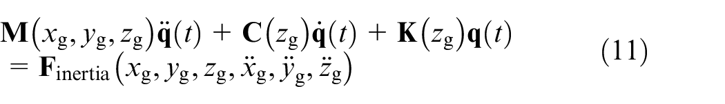
where
It can be seen that the derived dynamic equations are parameter-varying equations. The dynamic matrices vary with the feed positions, which reflect the position dependent structural dynamics. The input forces are a function of the feed positions and accelerations, which characterize the axis coupling inertial forces determined by the feed positions and accelerations.
Solution process of dynamic error of TCP relative to worktable
The DETW during the accelerating stage of one feed axis is simulated in this study. Let the feedrate is 5000 mm/min and the acceleration is 2
In order to calculate the feed acceleration, a simplified servo model is proposed, as shown in Figure 3. The mechanical system of feed drive is modeled using 2-DOF lumped model. Here
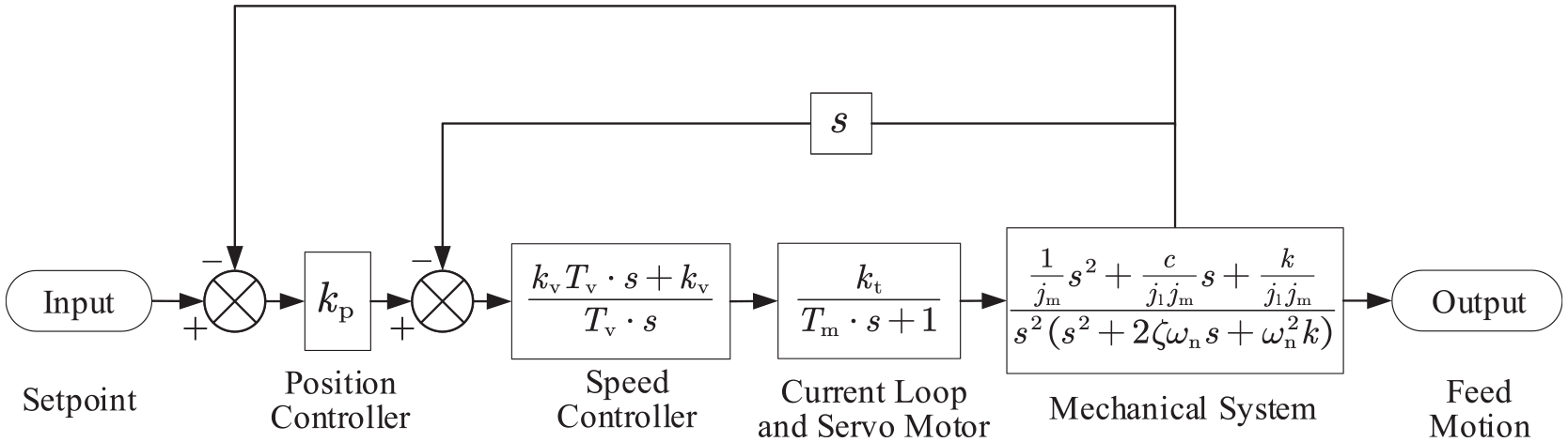
Simplified servo model.
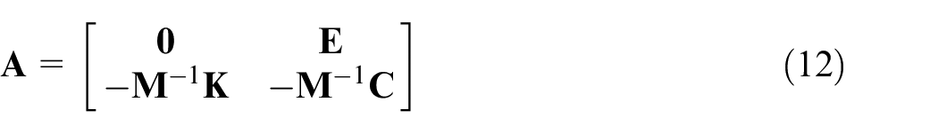
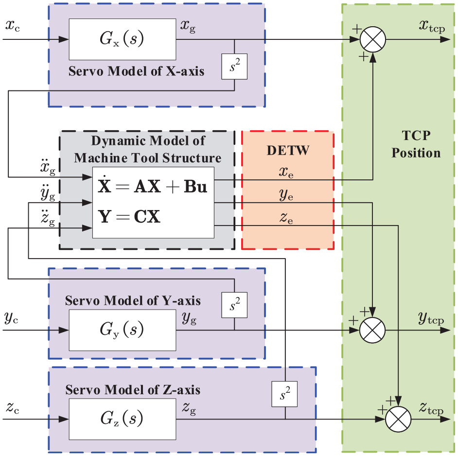
A multi-input-multi-output (MIMO) state space model of the system is proposed to calculate DETW. The input signals of the state space model are the feed accelerations of the three feed axes. The output signals of the state space model are DETW in X-, Y- and Z-direction. The state-dynamic matrix
The input matrix
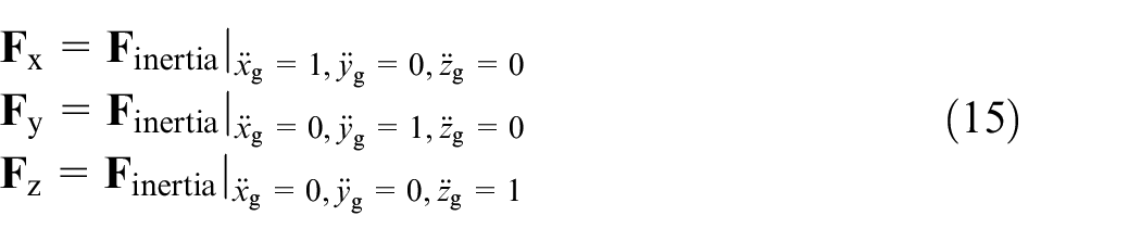
The input vector

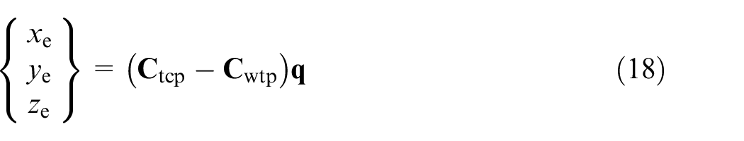
The transformation matrix of TCP with respect to the global reference frame RXYZ is
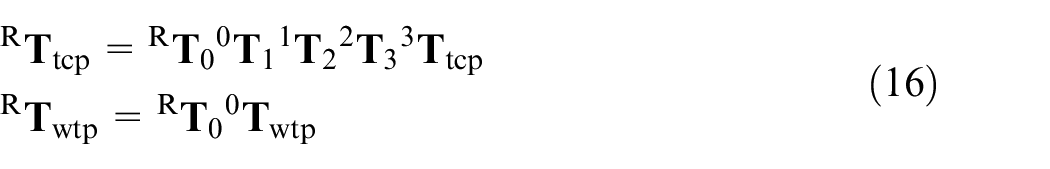
The translational vector
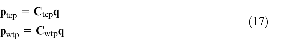
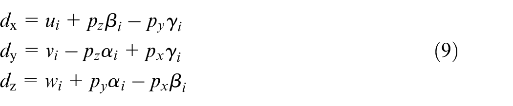
The DETW in X-, Y-, and Z-direction can be derived by equation (18). The expressions of
The output matrix

The above equations can be stiff ordinary differential equations (ODEs). Therefore, the solution algorithm for solving stiff ODEs was used in this study, such as ode15s and Gear method. The block diagram of the solution process is shown in Figure 4.
Block diagram of the solution process of dynamic error of TCP relative to worktable.
Experimental setup
Etalon LaserTracer MultiTrace system was used for measuring DETW. The experimental setup is shown in Figure 5. The sampling frequency was set to 1000 Hz. The maximum trace velocity of the measuring system was 10
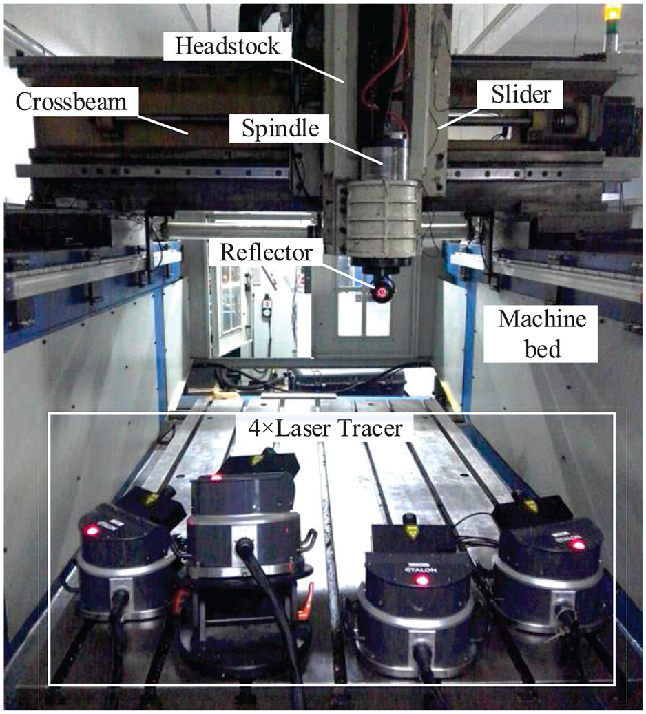
Experimental setup for measurement of dynamic error of TCP relative to worktable.
The feed rate was set to 5000
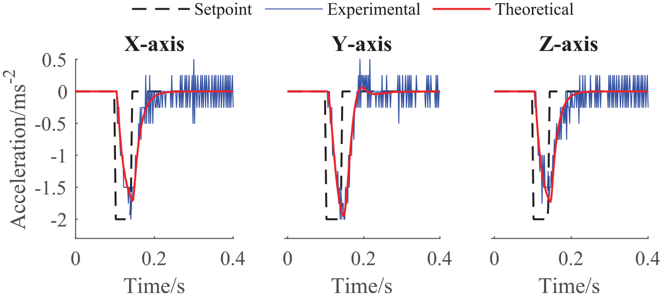
Experimental and simulated feed accelerations of X-, Y-, and Z-axis.
Results and discussion
Dynamic error of TCP relative to worktable
Figure 7 shows theoretical and experimental DETW in the orthogonal directions of feed direction during the accelerating stage of each feed axis. The feed positions were
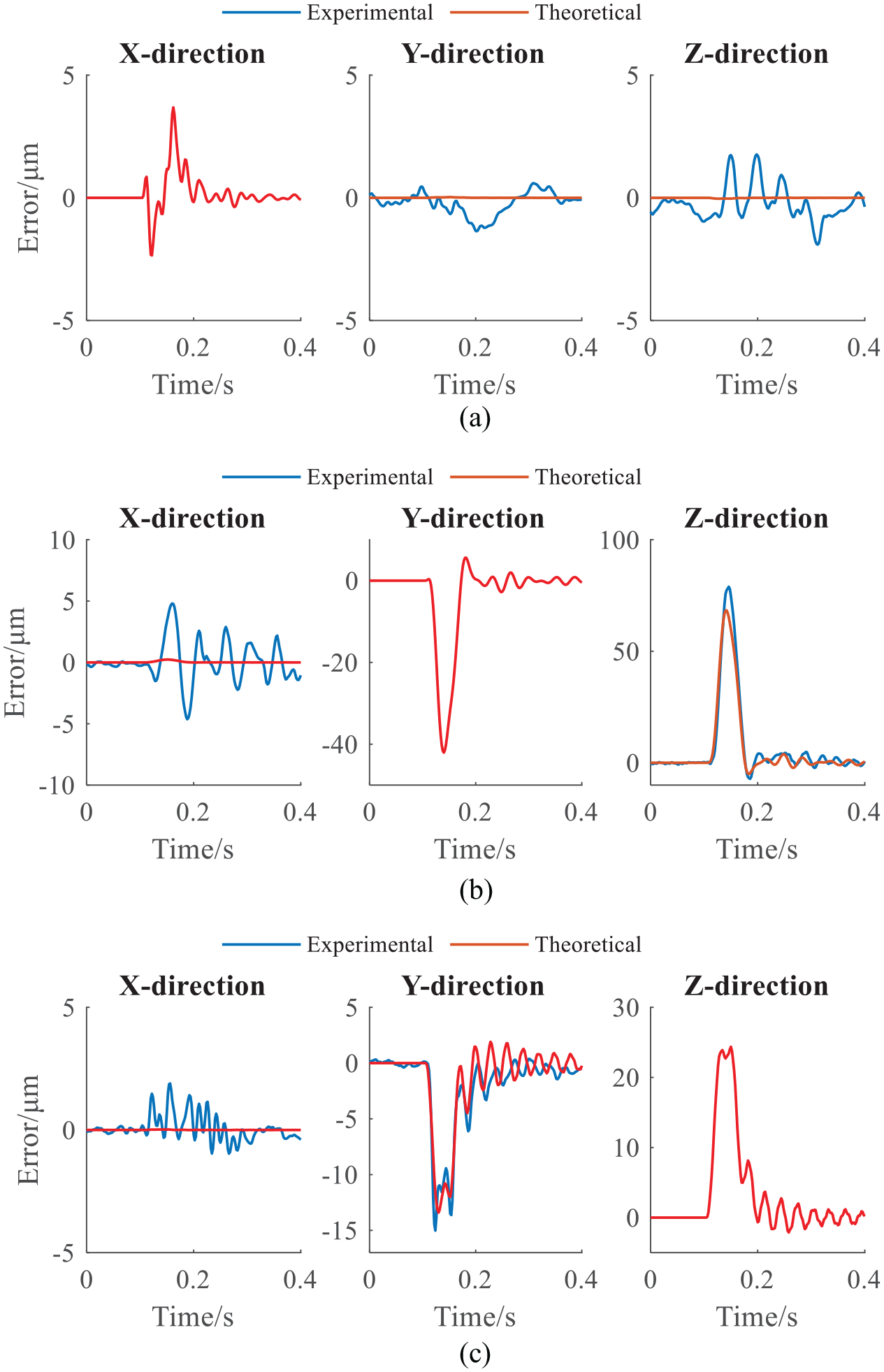
Dynamic error of TCP relative to worktable: (a) dynamic error during the accelerating stage of X-axis, (b) dynamic error during the accelerating stage of Y-axis, and (c) dynamic error during the accelerating stage of Z-axis.
The DETW in one direction is not only influenced by the feed axis in this direction but also influenced by other feed axes. Figure 7(a) shows that
In order to discuss to influence of structural dynamics on DETW, frequency domain analysis and numerical modal analysis are undertaken. Figure 8 shows the frequency responses of DETW. The excitation is the acceleration of one feed axis. Figure 9 shows the first 9 mode shapes. It is obvious that the second and third modes are the relevant modes to the DETW during the accelerating stage of Y- and Z-axis. The second mode is the most dominant mode for
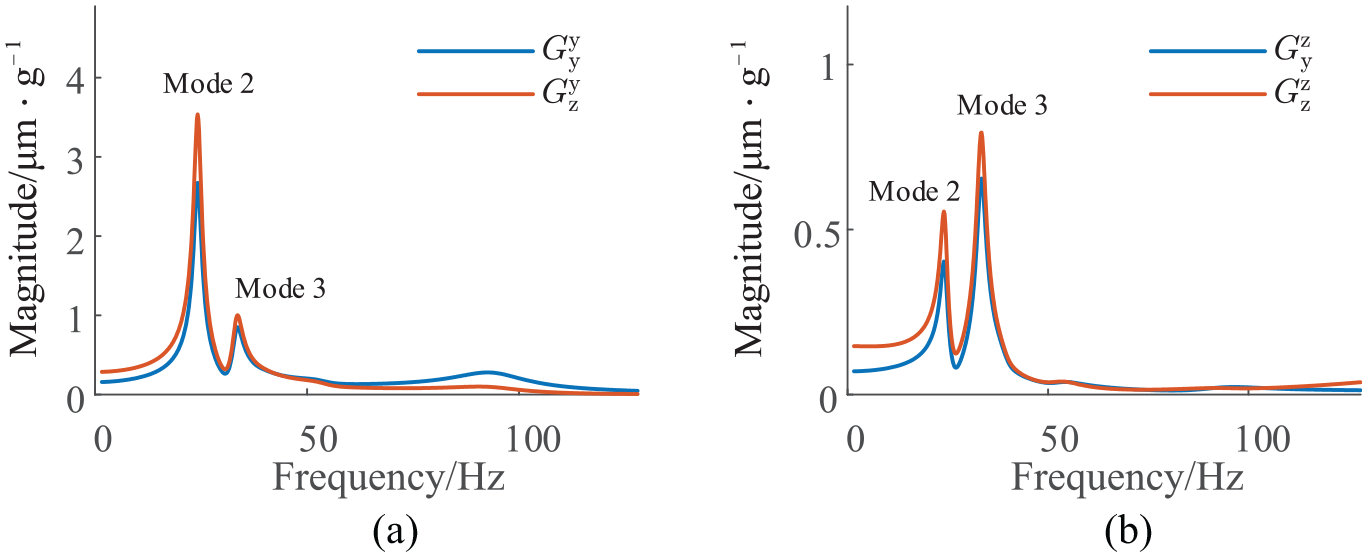
Frequency response of dynamic error: (a) frequency response of dynamic error during the accelerating stage of Y-axis and (b) frequency response of dynamic error during the accelerating stage of Z-axis.
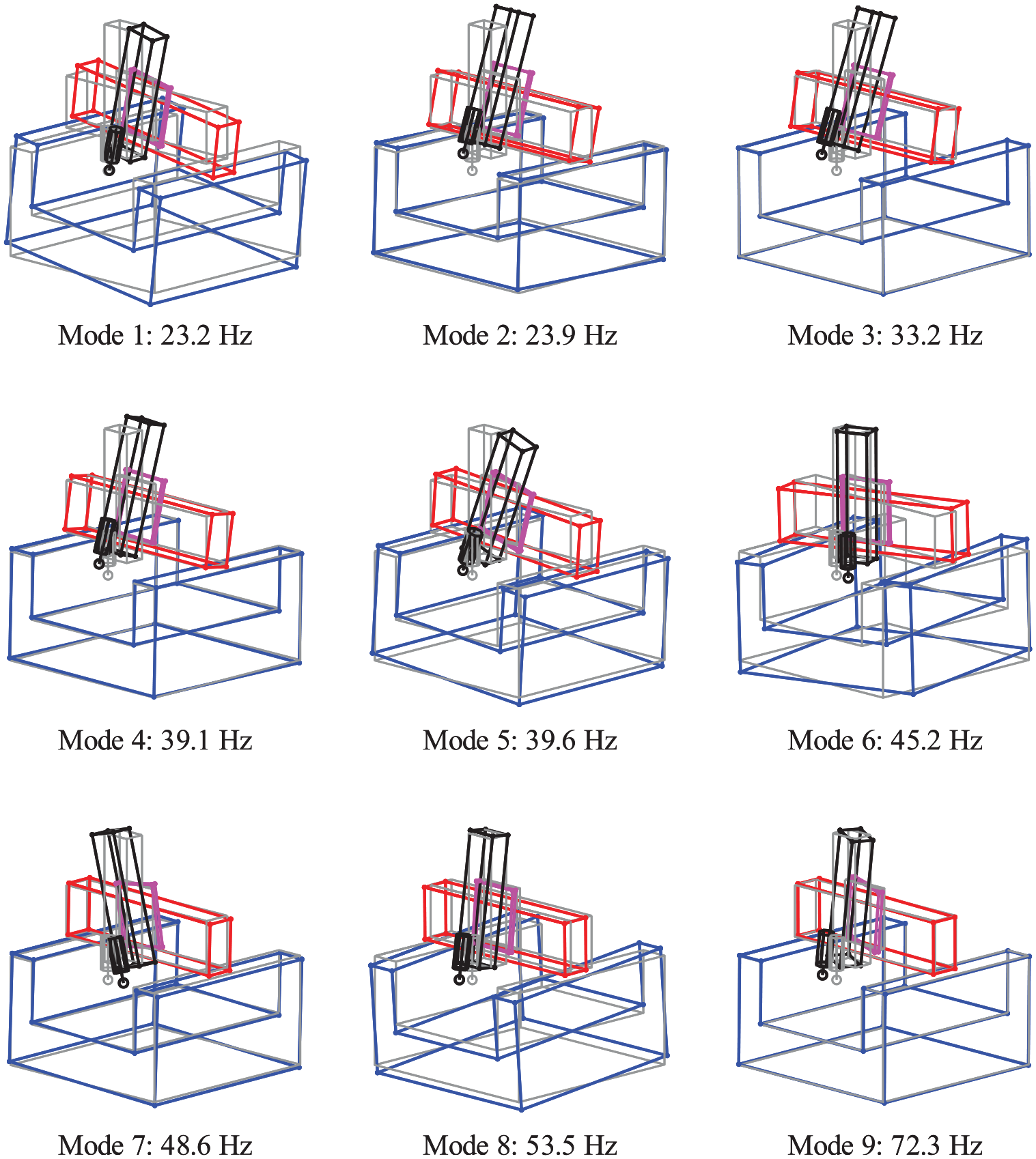
First 9 mode shapes of the machine tool structure.
The expressions of DETW is written as equations (24)–(26) in Appendix. The DETW in Y-direction is composed of the terms corresponding to
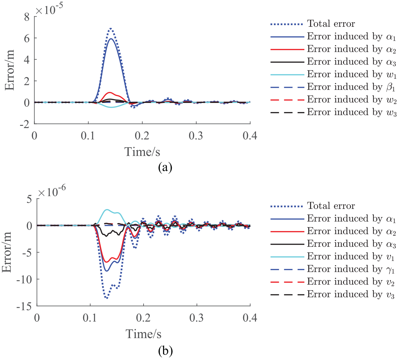
Composition of the dynamic error: (a) dynamic error in Z-direction during the accelerating stage of Y-axis (
Position dependency of dynamic error
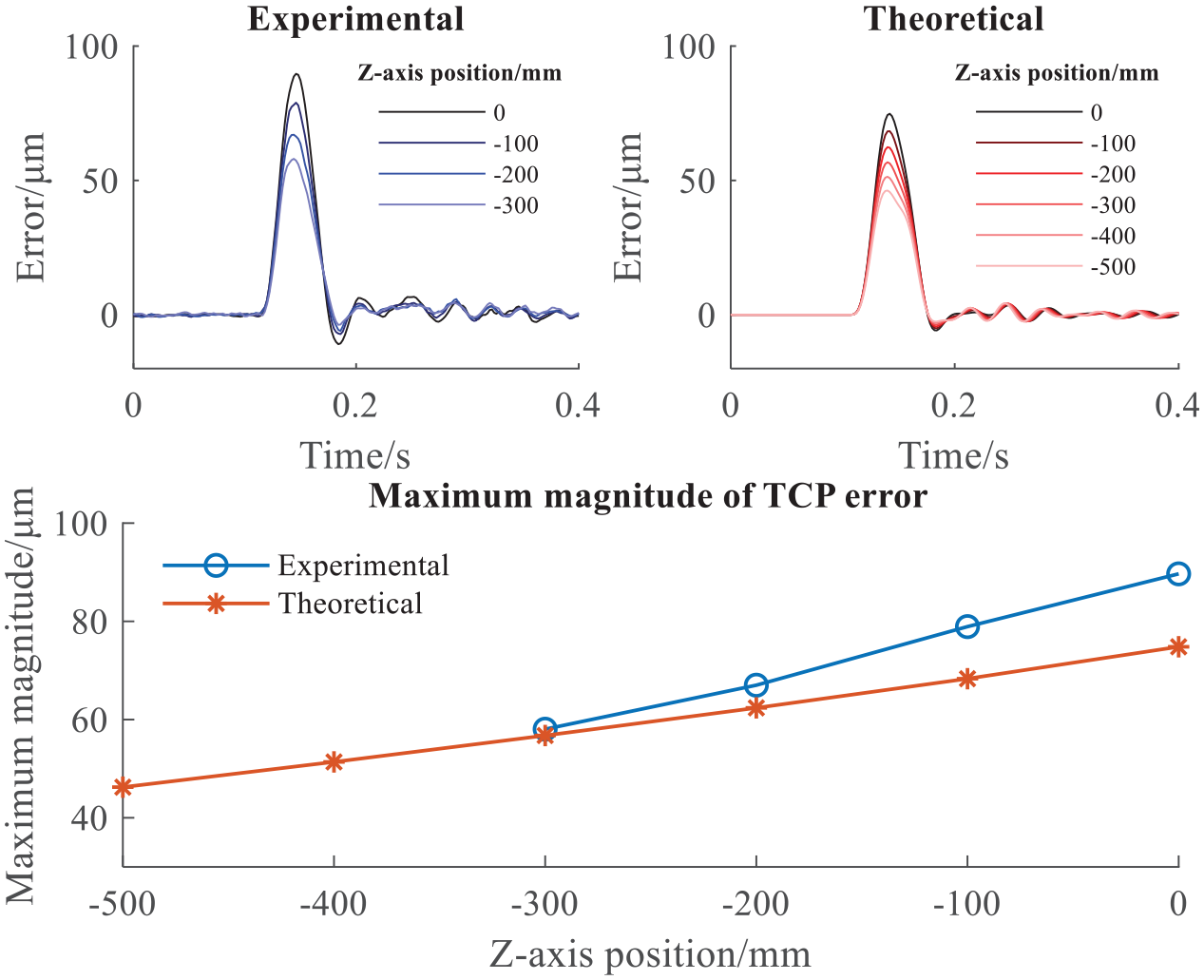
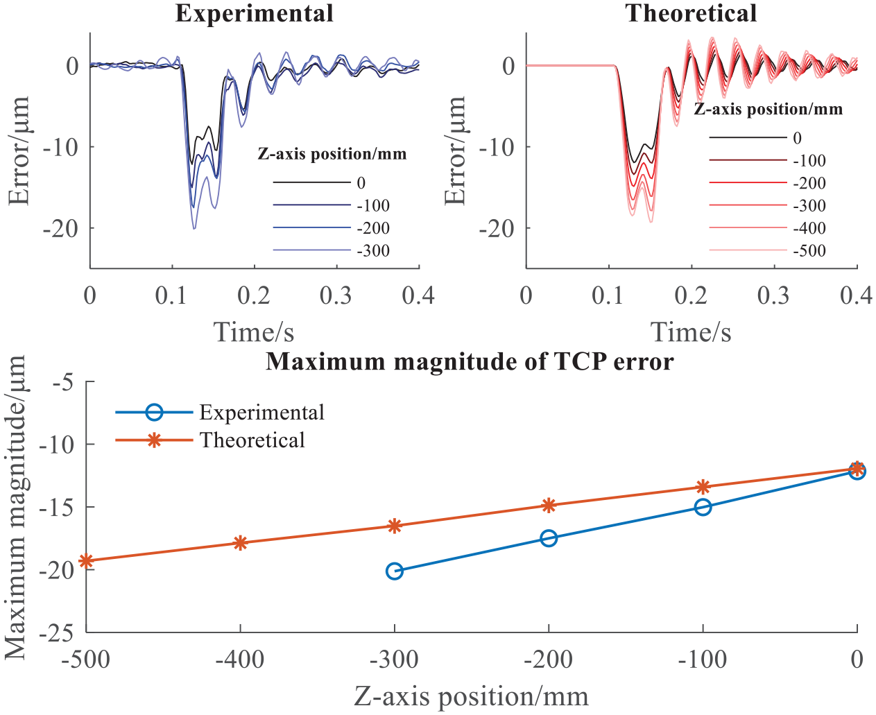
Position dependency of the dynamic error in Z-direction during the accelerating stage of Y-axis.
Position dependency of the dynamic error in Y-direction during the accelerating stage of Z-axis.
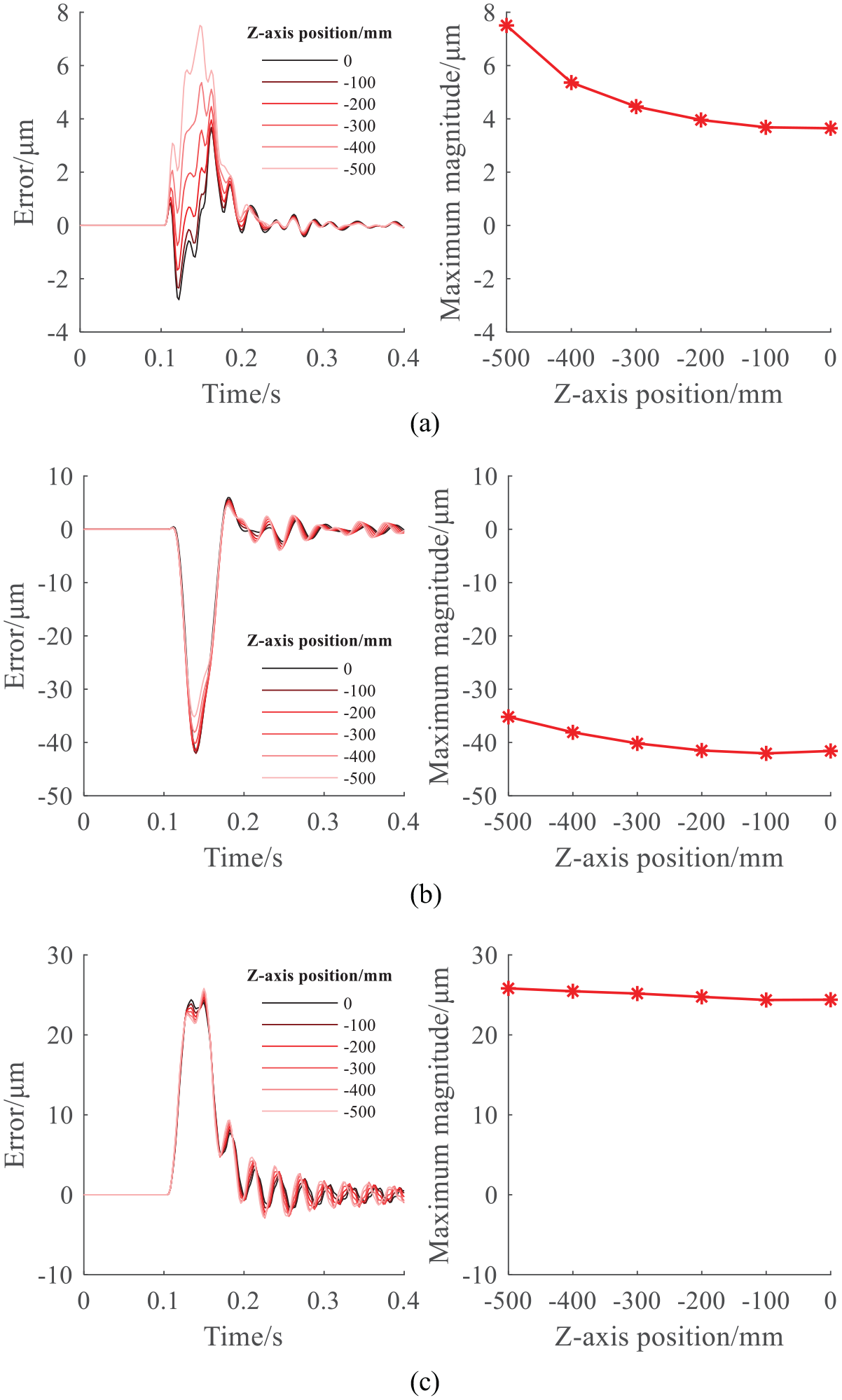
Position dependency of the dynamic error in feed direction: (a) dynamic error in X-direction during the accelerating stage of X-axis, (b) dynamic error in Y-direction during the accelerating stage of Y-axis, and (c) dynamic error in Z-direction during the accelerating stage of Z-axis.
The variations of inertial forces and structural dynamics with feed positions determine the position dependency of DETW. The inertial forces generated by Y-acceleration vary with Z-position. While the inertial forces generated by Z-acceleration do not vary with Z-position. The inertial forces can be expressed by equation (11) and can be calculated by multiplying
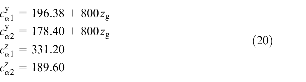
The dynamic response at TCP of the machine tool structure vary with the feed positions. And the dynamic response at TCP in different direction shows different trend. The expressions of DETW in X-, Y-, and Z-direction are given by equations (24)–(26) in Appendix. Considering the geometric parameters of the machine tool, these equations can be written as equations (21)–(23). These equations show that there is a negative correlation between
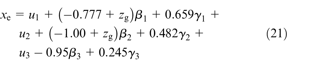
Figure 14 shows the variation of
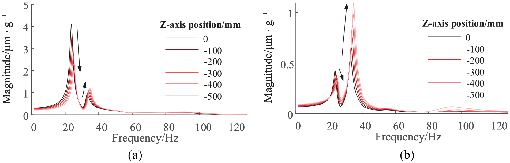
Frequency response for different Z-positions: (a) dynamic error in Z-direction during the accelerating stage of Y-axis and (b) dynamic error in Y-direction during the accelerating stage of Z-axis
Conclusions
This research was undertaken to model and analyze the dynamic error of TCP relative to worktable of multiaxis machine tool. The variations of structural dynamics and axis coupling inertial forces with feed positions are considered. The position dependency of dynamic error is discussed. The main conclusions are as follows:
The parameter-varying dynamic model of machine tool structure is proposed considering the variation of feed positions. The proposed model can describe the position dependent structural dynamics and inertial forces, and can calculate the dynamic error when the feed axes are in different positions.
The dynamic error in one direction is affected by the feed motions of multiple feed axes. The magnitudes of dynamic errors in Y- and Z-direction considerably vary with the feed position of Z-axis and have different varying trend. The relative decrease of the dynamic error in Y-direction is 35% when the feed position of Z-axis changes from 0 to
The frequency domain analysis, numerical modal analysis, and the compositions of dynamic error reflect the effect of the structural dynamics on the dynamic error. The results indicate that the linear guideways of crossbeam and slider are the weak components of the machine tool structure.
The expressions of TCP dynamic response and inertial forces reveal the reason why the dynamic errors in Y- and Z-direction have different varying trend. The position dependency of the dynamic error in Y-direction is only determined by the variation of inertial forces. While the position dependency of the dynamic error in Z-direction is only determined by the variation of TCP dynamic response.
Footnotes
Appendix
Declaration of conflicting interests
The author(s) declared no potential conflicts of interest with respect to the research, authorship, and/or publication of this article.
Funding
The author(s) disclosed receipt of the following financial support for the research, authorship, and/or publication of this article: This work was supported by the National Natural Science Foundation of China (No. 51905410, No. 51605374); China Postdoctoral Science Foundation (Nos. BX20180253, 219945); and the Fundamental Research Funds for the Central Universities.