
Abstract
This paper proposes a calibration method for continuous measurements with a double ball bar (DBB) used to identify the position-dependent geometric errors (PDGEs) of the rotary axes of five-axis machine tools. The different DBB installation modes for the rotary axes of the spindle and workbench are established, and the same initial DBB installation position is used for multiple tests. This approach minimizes the number of required DBB installations, which increases the measurement efficiency of the PDGEs of the rotary axes and reduces installation errors. PDGEs identification based on the adaptive least absolute shrinkage and selection operator (LASSO) method is proposed. By assigning coefficients to the PDGEs polynomial, the ill-conditioned problem of the identification process can be effectively avoided, thereby improving the identification accuracy. The measurement and identification methods proposed in this paper are verified by experiments on a five-axis machine tool. After compensation, the PDGEs are obviously reduced and the accuracy indexes of the circular trajectory tests performed under multiaxis synchronous control are obviously improved.
Keywords
Introduction
Five-axis machine tools have shown the ability to fabricate a large variety of precision components with complex surfaces that satisfactorily meet industrial demands. The two additional rotary axes give these machines a unique advantage over three-axis machines.1,2 However, the number of error sources increases as the number of motion axes increases, which inevitably decreases the accuracy of five-axis machine tools.3,4 Geometric errors are always one of the main quasi-static factors that influence the geometric accuracy of rotary axes.5,6 A five-axis machine tool with a tilting head and a rotary table has 12 position-dependent geometric errors (PDGEs) and 13 position-independent geometric errors (PIGEs) 7 ; thus, to ensure the efficiency and quality of component machining with freeform surfaces, the geometric accuracy of the motion axes must be calibrated quickly and precisely.
The geometric error of a machine tool must be measured before calibrating the geometric accuracy. Direct and indirect measurement methods are developed based on certain established measurement devices. 7 He 8 proposed a dual optical path method for measuring the geometric errors of the linear and rotary axes of a five-axis machine tool. Du 9 developed a method of composite trajectory including circular and non-circular motion based on the use of a cross-grid encoder. Liu 10 established a binocular-vision-based method for calibrating PIGEs of the rotary axis of an RTTTR-type (note that the R and T represent rotational and translational axes, respectively) five-axis machine tool. Ibaraki S 11 and Wang 12 proposed standard method for assessing the accuracy of five-axis machine tools using rectangular bosses and S-shaped test pieces, respectively. Zhang 13 proposed a three-point method based on sequential multilateration to measure the geometric error of machine tools with a laser tracker. Bringmann and Knapp 14 developed an identification algorithm for all PDGEs of rotary axes that used the “chase-the-ball” test. However, it is difficult to measure PDGEs or PIGEs of rotary axes through direct measurements.15,16 To our knowledge, no special measuring instruments can realize direct measurements of the geometric error of rotary axes without requiring a decoupling algorithm. Geometric error has unique characteristics both in quantity and in the intrinsic nature of the geometric error terms of different types of machine tools.12,17,18,19 This means that the geometric error measurement method developed for a five-axis machine tool with a tilting rotary table cannot be used for a five-axis machine tool with a tilting head and a rotary table. 12 In addition, few studies have measured the PDGEs of the rotary axes in a five-axis machine tool with a tilting head and a rotary table with few double ball bar (DBB) installations.
The characteristics of indirect measurement methods determine the necessity of establishing a decoupling algorithm in the process of geometric error identification. Multibody system theory and the homogeneous coordinate transformation method are common and important theoretical tools for characterizing the mapping relationship between geometric error terms and position and posture vectors.20,21 Lee et al 22 adopted a C1-type continuous function to characterize the PIGEs and PDGEs of a TTTTT-type five-axis machine tool, and the installation errors and PDGEs at different positions were simulated and analysed. Jaroslav 23 analysed special classes of matrices over dual numbers and established a multiaxis machine geometric error model with dual number calculus. Li et al 24 proposed an automatic modelling algorithm to represent the geometric error terms based on a combination of moving least squares and Chebyshev polynomials. Cheng et al. 25 established a volumetric geometric error model by combining exponential screw theory with topological structure and measured data. For PDGEs, polynomial models are effective at expressing their distributed features. Low-order polynomials are usually established in the identification process, which can lead to defects with lower accuracy, and ill-conditioned problems easily occur in complicated error identification models. A possible solution to this problem is simplifying the measurement method to avoid the probability of ill-conditioned problems, and then establish appropriate methods to improve identification accuracy.
Previous studies have mainly focused on geometric error measurements of a five-axis machine tool with a tilting rotary table and PIGEs of a five-axis machine tool with a tilting head and a rotary table.11,17,26 However, the measurement method for the PDGEs of the rotary axes in a five-axis machine tool with a tilting head and a rotary table lacks systematic research. In another respect, overfitting and ill-conditioned problems will increase the complexity of measurement and reduce the identification accuracy of the PDGEs of the rotary axes in a five-axis machine tool with a tilting head and a rotary table.
Structure of the proposed approach
In this paper, the contributions are listed hereafter. The first contribution is the proposed measurement method for the PDGEs of rotary axes in a five-axis machine tool with a tilting head, which is accomplished with minimal DBB installations. The other contribution is that the identification method based on the least absolute shrinkage and selection operator (LASSO) is established to improve the identification accuracy of the PDGEs. The approach presented in this paper consists of three main steps, as summarized in Figure 1.
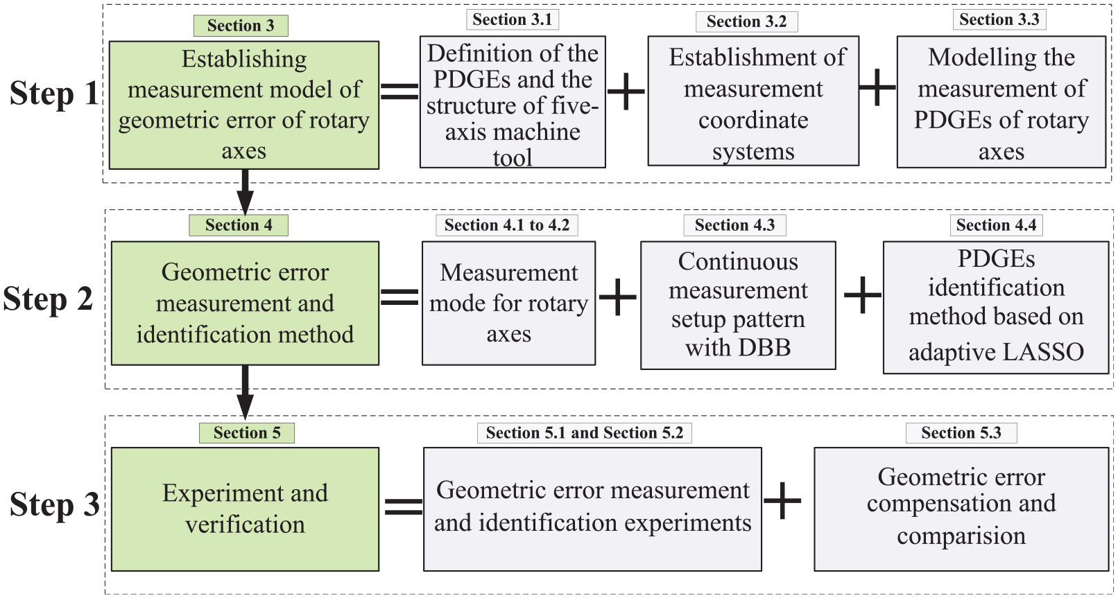
Framework of the proposed methodology.
Modelling the geometric error of the rotary axis of the five-axis machine tool
Definition of the machine tool structure and geometric error
The five-axis machine tool in this study consists of three linear axes (X-, Y-, and Z-axes), a tilting head (B-axis) and a rotary table (C-axis), as shown in Figure 2. According to the nature of rigid body motion, each motion axis has six degrees of freedom in the Cartesian coordinate system, and six motion errors exist in the corresponding direction of the motion axis.
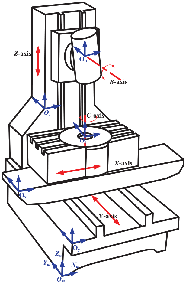
Schematic of the five-axis machine tool.
According to the definition of ISO 230-1, 27 PDGEs can be expressed with δij and εij, which represent the position error and angle error, respectively, wherein j represents the position coordinate and i represents the direction of error.
For the rotary axes in Figure 2, the six motion errors of the B-axis of the five-axis machine tool are position errors in the X, Y and Z directions, such as δxb, δyb, and δzb, and angle errors around the X, Y and Z-axes, such as εyb, εzb and εxb. For the C-axis, which contains position errors δxc, δyc, and δzc and angle errors are εxc, εyc and εzc.
Establishment of a measurement model for the PDGEs of the rotary axes
PDGEs can be described in the local coordinate system of the corresponding motion axis when the error model is established based on multibody system theory. The geometric error terms of the motion axis are defined in the local coordinate system of the motion axis itself rather than relative to the reference coordinate system of the computer numerical control (CNC) machine tool. This means that the measurement and identification of PDGEs should be performed in the local coordinate system of the motion axis itself. The local coordinate systems of the B- and C-axes are shown in Figure 2.
Modelling the motion error of the rotary axis
DBB is widely used to evaluate the performance of multiaxis machine tools. The PDGEs of the machine tool motion axis can be identified by circular trajectory tests with well-developed identification algorithms. The structure of the DBB is relatively simple, consisting of two precision balls and a magnetic telescoping bar.
Precision balls O1 and O2 are installed on the tool cup and centre mount, respectively. When there is relative motion between the measured parts in the machine tool, the displacement of the precision balls can be measured with the displacement sensor in the magnetic telescoping bar. The error of the motion radius and the error of the circular trajectory will be formed, and the PDGEs and PIGEs can be identified with an established geometric error model.
According to the multibody system theory and homogeneous transformation method, the position relationship between the feature body k and the adjacent low-order body unit l of five-axis machine tools can be expressed by the homogeneous transformation matrix as follows:

where
The positions of O1 and O2 in the measuring coordinate system are P1= [x1, y1, z1, 0]T and P2= [x2, y2, z2, 0]T, respectively. The accuracy of the rotary axes would not be affected by the PDGEs under ideal conditions, and the ideal transformation matrices of O1 and O2 are shown in equation (2).
When asynchronous motion exists in the C- and B-axes, one precision ball moves with the tool cup or centre mount while the other remains stationary. Hence, the matrix responding to the stationary axis is the unit matrix, and the C- and B-axes are set to exhibit asynchronous motion to enable efficient and accurate measurements.
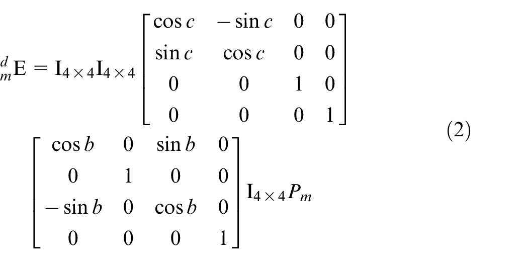
where Pm is the position of O1 and O2 in the measuring coordinate system.
The accuracy of the rotary axes would be affected by PDGEs under actual conditions, and the transformation matrices of O1 and O2 are expressed as follows:
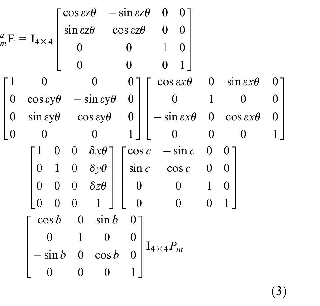
where θ represents the rotation angle of the C- and B-axes.
The distance between the precision balls of the DBB in the ideal state and the actual state can be determined by the positions of O1 and O2. The expression of the distance between the precision balls of the DBB is as follows:

The length variation between the precision balls of the DBB is a space error vector in three directions, which can be expressed as follows:

The expression of the error vector can be determined by substituting the homogeneous transformation matrix. Conducting asynchronous motion of the C- and B-axes can effectively avoid the influence of servo error and is conducive to identifying the PDGEs of the rotary axes accurately and effectively. Therefore, when measuring the geometric error of the C-axis, it is necessary to ensure that the precision ball at the tool cup is not affected by the motion of the B-axis, and the motion of the C-axis and linear axes should be minimized when performing the circular trajectory test to identify the geometric error of the B-axis. The length variations along the orthogonal directions of the spatial error vector of the C- and B-axes can be obtained by circular trajectory measurements. These length variations can be expressed as follows:
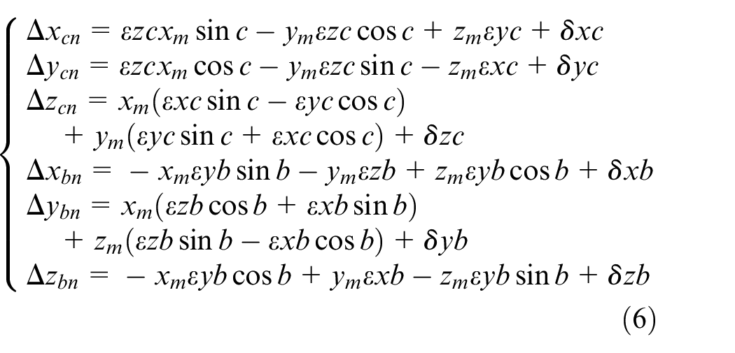
where n represents the measurement mode under different installation positions.
The PDGEs of the rotary axes can be identified by the least squares method, and different measuring positions can be predefined. The analytical solutions of six geometric errors are determined from the measured data of the circular trajectory.
Measurement patterns for determining the geometric errors of the rotary axes
Circular trajectory tests can be conducted in the XY, ZX and YZ planes without having to setup and recentre the DBB between each test. The initial position of the precision ball of the DBB is set in the measuring coordinates to ensure that the circular trajectory measurement is carried out successively at the same initial installation position, and then the installation position of the DBB is changed to implement the trajectory measurement at the next installation position. In this process, the magnetic telescoping bar of the DBB does not have to separate from the tool cup and centre mount, and it essentially belongs to the same installation. The geometric errors of the two rotary axes in the identification process are linearly independent when setting the motion forms of the rotary axes.
Setup and measurement mode for the C-axis
While the position of the precision ball on the tool cup moves along the measuring coordinate system, which is defined by the C-axis of the machine tool, and the other motion axes remain stationary, the length variation of the DBB will be affected by the precision ball that is clamped in the centre mount when the C-axis rotates. From the expression of the measurement model of PDGEs (equation (6)), it can be found that the establishment of a non-singular matrix of PDGEs is an essential condition for identifying six geometric errors of the rotary axis. Thus, six linear independent positive definite equations are constructed. Note that xi, yi and zi (i = 1, 2… 6) in equation (6) correspond to the initial installation position of the precision ball on one side of the worktable in the measuring coordinate system. Three installations and six measurement patterns were planned for identifying the PDGEs of the rotary table on the five-axis machine tool with a tilting head. The installation and measurement pattern are shown in Figure 3.
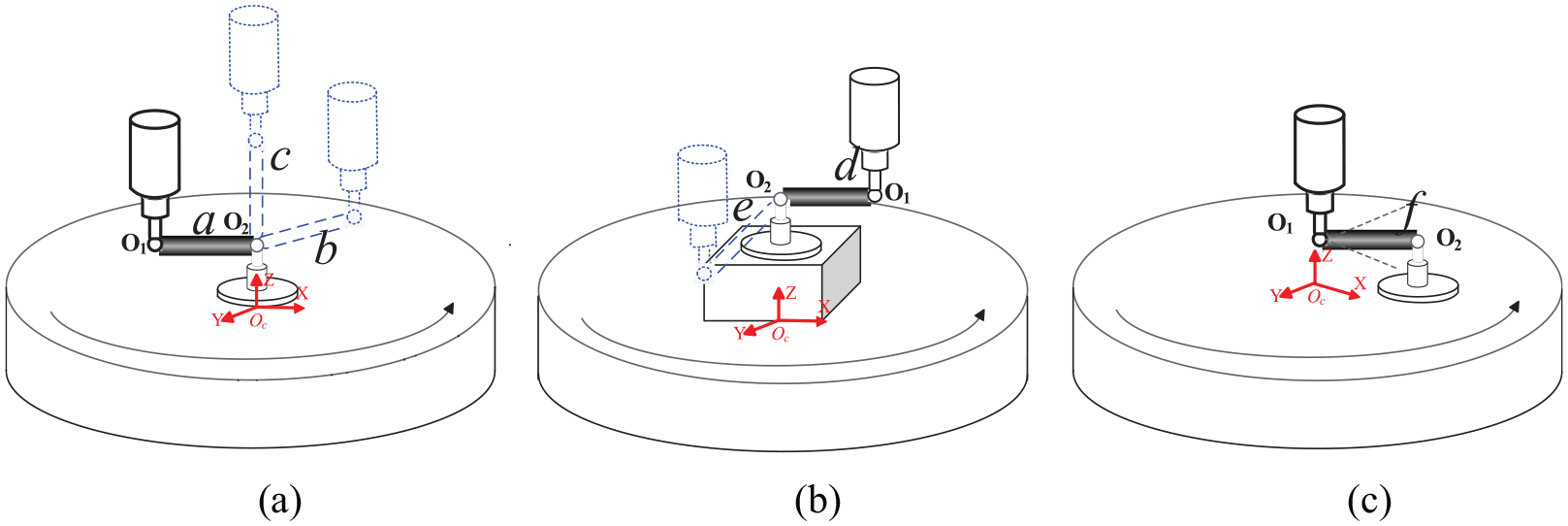
DBB setup and measurement mode for the C-axis: (a) First setup, (b) Second setup, (c) Third setup.
In the first installation of the DBB, the telescoping bar of the DBB is installed along the direction of the X-, Y- and Z-axes. In the second installation of the DBB, the telescoping bar of the DBB is installed along the direction of the X- and Y-axes after resetting the centre mount along the C-axis. In the third installation of the DBB, O2 of the DBB is installed along the direction of the angular bisector between the X-axis and the negative direction of the Y-axis. The C-axis rotates in the XY plane, while the B-axis and other axes are kept stationary. The initial locations of O1 and O2 in the measuring coordinate system are shown in Figure 3.
Setup and measurement mode for the B-axis
The location of the precision ball that is attached to the tool cup does not coincide with the B-axis because there is a larger distance between the cutting tool end and the B-axis, which prevents the tool cup of the DBB from being accurately installed in line with the B-axis. To perform circular or arc trajectory tests, it is necessary to conduct multiaxis motion of the B-axis and linear axes.
The local coordinate system of the B-axis is used as the reference coordinate system for measuring the PDGEs of the B-axis. The installation and measurement pattern are shown in Figure 4.
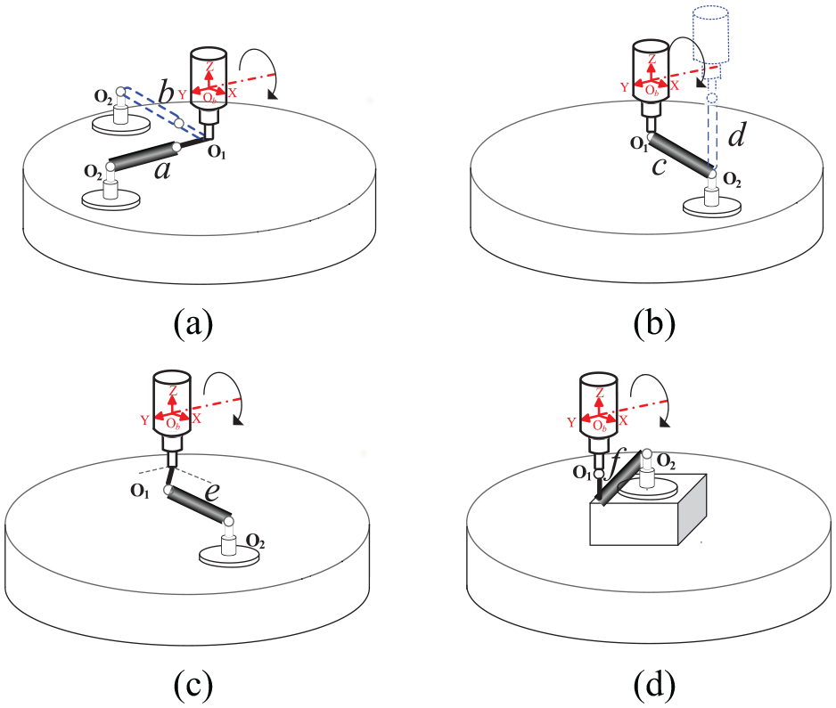
DBB setup and measurement mode for the B-axis: (a) First DBB setup, (b) Second DBB setup, (c) Third DBB setup, (d) Fourth DBB setup.
In the first installation of the DBB, the telescoping bar of the DBB is installed along the direction of the X- and Y-axes, O1 is installed in the direction of the spindle, O2 is installed in the direction of the Y- or X-axes, and the distance between the precision balls is L+L1. In the second installation of the DBB, the telescoping bar of the DBB is installed along the direction of the X- and Z- axes, O1 is installed in the direction of the spindle, O2 is installed in the direction of X-axis, and the distance between the precision balls is L. In the third installation of the DBB, the telescoping bar of the DBB is installed and parallel to the direction of the X-axis, O1 is installed along the direction of the angular bisector between the X- and Y-axes, and the distance between the precision balls is L. In the fourth installation of the DBB, the telescoping bar of the DBB is installed along the direction of the X-axis, O1 is installed in the direction of the spindle, the distance between the precision balls is L, and O2 is on the centre mount that is clamped on the rotary table with a distance of H1. The B-axis rotates, the X- and Z-axes exhibit synchronous motion, and the other axes are kept stationary when performing circular or arc trajectory tests.
Continuous measurement mode based on the DBB setup
Multiple installations and measurements are bound to reduce the accuracy of the measurement results; however, circular trajectory testing with a DBB in different planes can be carried out continuously at the same initial installation position, and the DBB needs to be installed only once. Based on the above characteristics of the test setups of the DBB, to perform a volumetric test, five DBB setups were proposed in this section, wherein the DBB needed to move through the test trajectory shown in Figure 5.
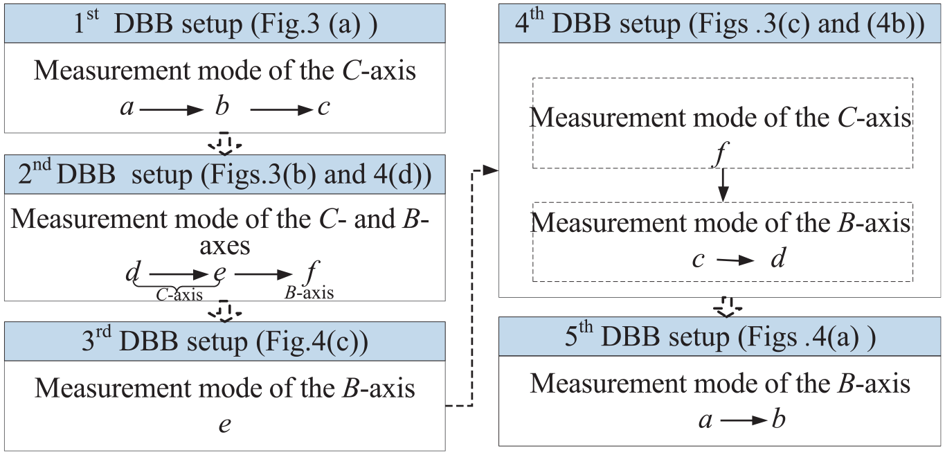
Measurement process based on five DBB setups.
As shown in Figure 5, the initial installation position of the DBB is consistent for the measurement mode of the C- and B-axes in the 4th DBB setup. Upon DBB installation, the influence of the installation error can be substantially avoided, and the measurement efficiency can be effectively improved.
PDGEs identification based on the adaptive LASSO method
The geometric errors of the rotary axis are related to the command position of the rotary axis, that is, the motion errors change with respect to the command position. Therefore, the motion errors of the C- and B-axes (the rotary axes) can be expressed as functions of the rotation angles. The PDGEs can be expressed as polynomial functions of the motion variables.9,20,27 The polynomial model of translational and angular errors of the rotary axes can be defined as follows:
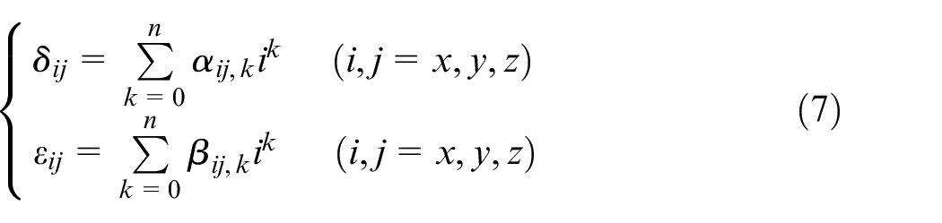
where αij and βij are the coefficients of the translational and angular error polynomials, respectively, and k is the order of the geometric error polynomials.
By combining equations (6) and (7), a linear mapping model between the geometric error source and the variation in DBB can be expressed as follows:

where Δl is the variation in the DBB in the five different setup positions, D is composed of the initial coordinates of O1 and O2 and the command value of the motion axes, and E is a vector consisting of translational and angular errors, which are functions of the coefficients and order of the geometric error polynomials.
The values of geometric error can be identified by solving equation (6), and the ill-conditioned problem can be effectively avoided when the initial position of the magnetic ball is installed properly. For the PDGEs of the rotary axes of the machine tool, the function forms are nonlinear, the coefficients of the geometric error polynomials are biased estimations, and the accuracy of the identified geometric error is always susceptible to measurement uncertainty. Hence, the adaptive LASSO regression method is adopted to overcome this problem in this paper. 28 The adaptive LASSO regression method is a regularization approach that simultaneously chooses variables and estimates parameters, and different weights are assigned to coefficients of the translational and angular error polynomials. The expression of the adaptive LASSO method model is defined as follows:
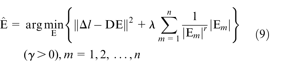
where λ and r are adjustment parameters.
In the adaptive LASSO method, different parameters of polynomial coefficients can be adjusted with a penalty function r; the more important the parameters of the polynomial coefficients, the smaller the adjustment parameters, and vice versa.
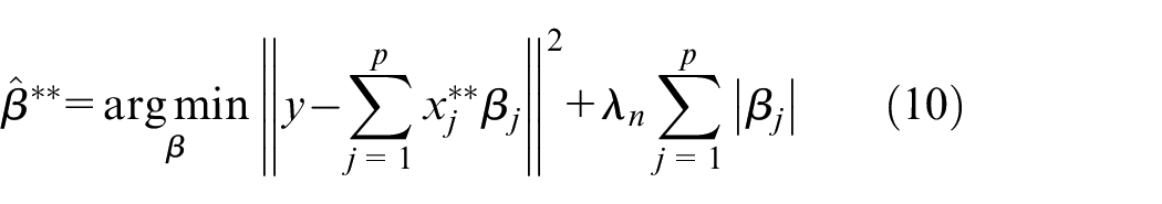
The adaptive LASSO estimates in equation (9) can be determined with the least angle regression (LARS) algorithm. 29 The basic steps are as follows:
1) Define
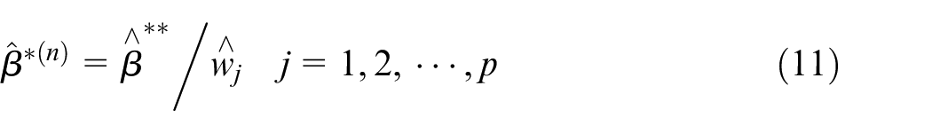
2) All adjustment parameters λ and n can be determined by solving the LASSO problem
3) Output the value of
According to the properties of the geometric error terms, the corresponding values are generated in the form of cubic polynomials.20,30 The measurement results show that the identification precision will be affected by the number of measurement points Mp and the order n of the polynomial.
Experimental verification
To reduce the influence of the environment on the measurement results, an air conditioning device is used to maintain the ambient temperature and relative humidity during the experiment at 20±2 °C and 60 ± 10% RH, respectively. A Renishaw QC 20-W type DBB is adopted for measuring the geometric error of the rotary axes. The measurement accuracy of the DBB is ±(0.7 + L·0.3%) μm, where L stands for the length covered by the measurement and the nominal length of L is 100 mm, L1 is 100 mm and the feed speed of the motion is 500 mm/min.
DBB setup and measurement
The travel range of the C-axis is from 0° to 360°, whereas the travel range of the B-axis is from −5° to 5°. The measured range of the B-axis is from −20° to 90° due to the limit of travel of the linear axis. The angular overshoot of the arc trajectories for the C- and B-axes is 5°. The total measurement processes include twelve measurement tests under five DBB setups. The measurement processes of the 1st DBB setup are depicted in Figure 3(a), and the details are as follows:
First, the rotary axes are reset to the initial position.
Second, the initial position (given in the measuring coordinate system hereinafter) of O2 is (0, 0, 60), and O1 is installed at (–100, 0, 60), (0, 100, 60) and (0, 0, 160) in the a, b and c measurement modes, respectively.
Finally, the B-axis is kept stationary and the C-axis is rotated from 0° to 360°, and then three modes of the C-axis measurement test are performed in sequence. After performing one mode of the C-axis measurement test, the C-axis is rotated to the initial position where C=0° without needing to install the DBB again, and the initial position of the magnetic ball is positioned at the predefined initial position in the measuring coordinate system.
The measurement processes of the 2nd DBB setup are depicted in Figures 3(b) and 4(d), and the details are as follows:
First, the rotary axes are reset to the initial position.
Second, the initial position of O2 is (0, 0, 120), and O1 is installed at (–100, 0, 120) and (0, 100, 120) in the d and e measurement modes, respectively. The B-axis is kept stationary and the C-axis is rotated from 0° to 360°, and the 2 modes of the C-axis measurement test are performed in sequence.
Finally, in the f measurement mode of the B-axis, the initial position of O1 is (0, 0, 260), and in the f measurement mode, O2 is installed at (0, 100, 260). The C-axis is kept stationary while the B-axis rotates from 0° to 90°.
The measurement processes of the 3rd DBB setup are depicted in Figure 4(c), and the details are as follows:
First, the rotary axes are reset to the initial position.
Second, the initial position of O1 is (35.36, 35.36, 260), and in the e measurement mode, the initial position of O2 is (135.36, 35.36, 260).
Finally, the C-axis is kept stationary while the B-axis is rotated from 0° to 90°, and the e measurement mode of the B-axis measurement test is performed.
The measurement process of the 4th DBB setup are depicted in Figure 3(c) and Figure 4(b), and the details are as follows:
First, the rotary axes are reset to the initial position.
Second, the initial position of O1 is (0, 0, 60), and in the f measurement mode, O2 is installed at (–70.71, 70.71, 60); the B-axis is kept stationary while the C-axis rotates from 0° to 360°.
Finally, the initial position of O1 is (0, 0, 260), and in the c and d measurement modes, the initial position of O2 is (100, 0, 260) and (0, 100, 360), respectively. Then, the C-axis is kept stationary while the B-axis is rotated from 0° to 90°, and the c and d modes of the B-axis measurement test are performed in sequence.
The measurement processes of 5th DBB setup are depicted in Figure 4(a), and the details are as follows:
First, the rotary axes are reset to the initial position.
Second, the initial position of O1 is (0, 0, 260), and in the a and b measurement modes, the initial position of O2 is (0, 150, 260) and (–150, 0, 260), respectively.
Finally, the C-axis is kept stationary while the B-axis is rotated from 0° to 90°, and the measurement tests in the a and b modes are performed in sequence.
During the C-axis measurement tests only the C-axis rotation is needed, and the six measurement tests required just three DBB setups, thereby greatly enhancing the measurement efficiency. The measurement process does not include synchronous motions of other axes, which increases the measurement accuracy. The B-axis measurement tests also minimize the number of DBB setups, and during the B-axis measurement tests, the other two axes are kept stationary, thereby offering better measurement consistency.
Identification result of the PDGEs of the rotary axes
In the twelve measurement modes of the five DBB setups, circular trajectory tests were carried out three times under the same experimental conditions to avoid disturbance according to ISO 230-1. Note that Δl can be determined with the measurement data of the circular trajectory test with the DBB. In this paper, the number of measuring points Mp is 180 and 45 for the C- and B-axes, respectively, and n = 3 is applied to establish the identification model. The LARS algorithm was used to obtain the adaptive LASSO parameter, and the adjustment parameters λ are 8.31 × 10⁻⁴ and 7.92 × 10⁻⁴ for the C- and B-axes, respectively. The identified values of PDGEs can be determined by substituting the values of the adjustment parameters into equations (4)–(6). The identified PDGEs of the C-axis are shown in Figure 6(a)–(d).
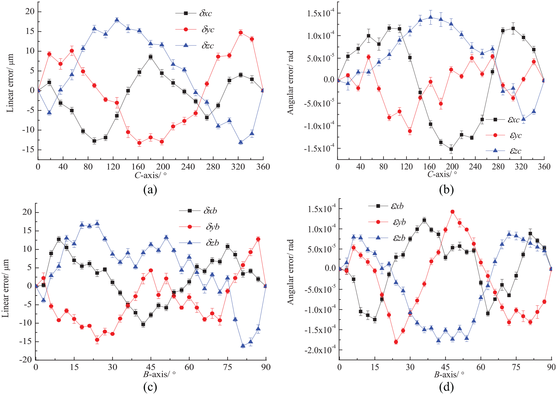
Identified PDGE results without compensation: (a) Linear errors of the C-axis, (b) Angle errors of the C-axis, (c) Linear errors of the B-axis, (d) Angle errors of the B-axis.
Figure 6 shows the mean of three measurements, and the error bar represents the expanded uncertainty. The maximum linear errors and angle errors of the C-axis were 1.4 μm and 3.2″ for the measured stroke, respectively. The maximum linear errors and angle errors of the B-axis were 1.7 μm and 3.5″ for the measured stroke, respectively. The uncertainty of the measurement and identification results was smaller than the repeatable positioning accuracy of the motion axes; thus, no significant difference existed among multiple measurements, and the measurement and identification accuracy had satisfactory consistency.
Geometric error compensation and accuracy comparison
The identified PDGEs can be compensated by generating new numerical control (NC) codes with inverse kinematic operation or post-processing software based on a well-defined compensation method,3,31 and the same measurements were performed based on the five DBB setups. Then, the identified PDGEs were determined after compensation. As shown in Figures 7(a) and (b), for the linear error of the C-axis, the average compensation rate was greater than 51.5%, and the maximum compensation rate was 74.6%. For the angle error of the C-axis, the average compensation rate was greater than 52.7%, and the maximum compensation rate was 80.9%.
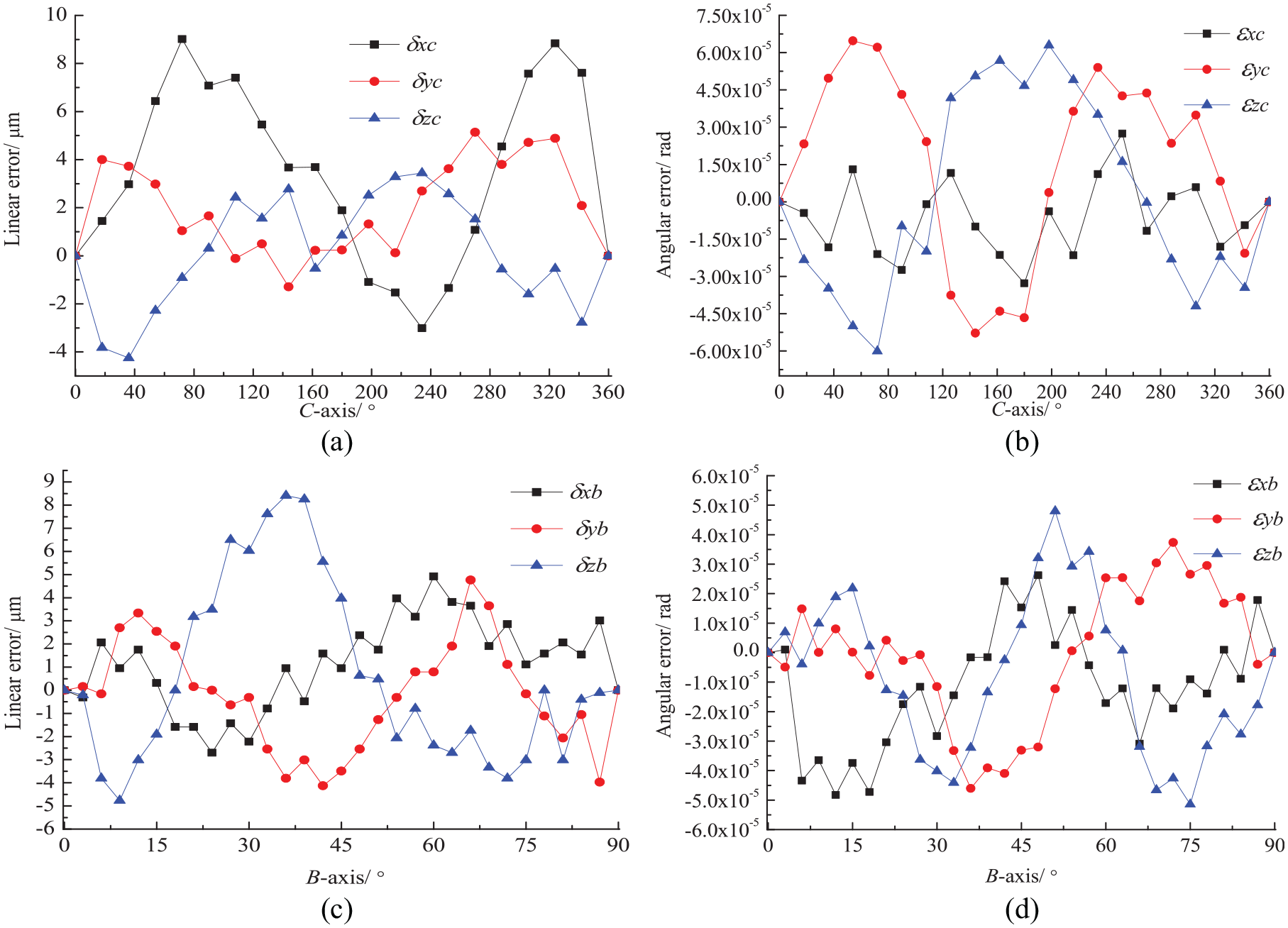
Identified PDGEs results with compensation: (a) Linear errors of the C-axis, (b) Angle errors of the C-axis, (c) Linear errors of the B-axis, (d) Angle errors of the B-axis.
As shown in Figures 7(c) and (d), for the linear error of the B-axis, the average compensation rate was greater than 68.4%, and the maximum compensation rate was 82.8%. For the angle error of the B-axis, the average compensation rate was greater than 64.6%, and the maximum compensation rate was 73.8%.
To further verify the identification accuracy of the method proposed in this paper, an experiment was carried out to compare the results from the proposed method with those from other common measurement methods; moreover, the compensation effects were analysed. ISO 10791-6:2014 32 specifies the measurement trajectory of an equivalent cone frustum with synchronous motion of the linear axes and rotary axes, as shown in Figure 8(a). The experimental setup of a DBB on a five-axis machine tool with a tilting head and a rotary table is shown in Figure 8(b).
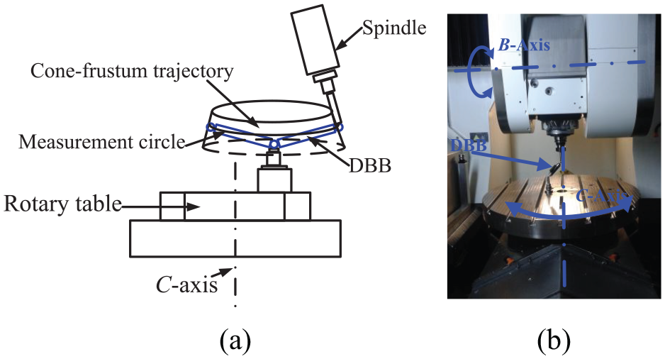
Cone frustum trajectory test setup: (a) Schematic of measurement trajectory and (b) Experimental DBB setup.
In the measurement stage, the inclined angle between the base of the measurement circle and the table surface is 30°, the apex angle of the cone frustum is 10°, the centre offset between the centre mount and the axis of the rotary table is 50 mm, and the feeding speed is 1000 mm/min, following the guidelines in ISO 10791-6:2014. Three measurements are conducted under the same experimental conditions and different compensation parameters.
A comparison of the equivalent cone frustum test results from the proposed method and the method in Jiang et al. 33 is shown in Figure 9.
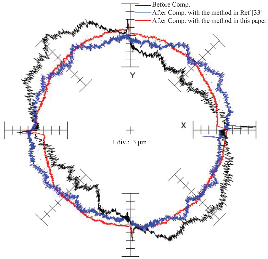
Comparison of measured trajectories.
As shown in Figure 9, the average radius deviation of the circular trajectory is 17.0 μm before PDGEs compensation, and the circular deviation of the circular trajectory is 25.3 µm. After the geometric error is compensated with the method in Jiang et al., 33 the average radius deviation of the circular trajectory is 11.4 μm, and the circular deviation of the circular trajectory is 14.0 µm. After error compensation is carried out with the method proposed in this paper, the average radius deviation and circular deviation of the circular trajectory are 6.4 µm and 8.6 µm, respectively.
After error compensation by means of the values of multiple measurements, the radius deviation and circular deviation are reduced by 44.7% and 32.9%, respectively. After compensating for the error based on five measurements and identification with the adaptive LASSO method, the radius deviation and circular deviation are reduced by 66.0% and 62.3%, respectively.
Conclusion
This paper proposes a successful measurement approach to identify 12 PDGEs of the rotary axes of a five-axis machine tool with a tilting head and a rotary table. The proposed systematic approach not only improves the measurement efficiency and reduces setup errors by setting the initial installation position of the DBB but also avoids the loss of PDGE identification accuracy caused by fitting and ill-conditioned problems. Validation of the measurement and identification results are also demonstrated in this study.
In this paper, we focus on the measurement and identification of PDGEs of the rotary axes of a five-axis machine tool with a tilting head and a rotary table. However, the PIGEs, thermal effect, load effect and other factors can cause variations in the quasi-static accuracy of the rotary axes of a five-axis machine tool machine tool; these effects should be taken into consideration in future studies.
Footnotes
Appendix 1
Declaration of Conflicting Interests
The author(s) declared no potential conflicts of interest with respect to the research, authorship, and/or publication of this article.
Funding
The author(s) disclosed receipt of the following financial support for the research, authorship, and/or publication of this article: The reported research was funded by the Science and Technology Development Special Project of Central Guide the Local Government of China (No. 2020ZY0002), the Natural Science Foundation of Inner Mongolia (No. 2019BS05008), the Inner Mongolia University of Technology Natural Science Foundation of China (No. BS201913), the National Natural Science Foundation of China (No. 61763036) and the National Key R&D Program of China (No. 2018YFB1307501).