
Abstract
The objective of this research is to develop a novel correction mechanism to reduce the fluctuation range of tools in numerical control (NC) machining. Error compensation is an effective method to improve the machining accuracy of a machine tool. If the difference between two adjacent compensation data is too large, the fluctuation range of the tool will increase, which will seriously affect the surface quality of the machined parts in mechanical machining. The methodology used in compensation data processing is a simplex method of linear programming. This method reduces the fluctuation range of the tool and optimizes the tool path. The important aspect of software error compensation is to modify the initial compensation data by using an iterative method, and then the corrected tool path data are converted into actual compensated NC codes by using a postprocessor, which is implemented on the compensation module to ensure a smooth running path of the tool. The generated, calibrated, and amended NC codes were immediately fed to the machine tool controller. This technique was verified by using repeated measurements. The results of the experiments demonstrate efficient compensation and significant improvement in the machining accuracy of the NC machine tool.
Introduction
With the rapid development of the manufacturing industry and the sharp improvement in machining level, the requirement for workpiece machining accuracy is increasing. Numerical control (NC) machine tools used to treat accuracy directly affect the accuracy of the workpiece dimensions. However, there are many factors that can lead to inaccurate machine tools, such as thermal, tool-wear-induced, control, and geometric errors.1,2
There is an effective method to improve machining accuracy by compensating for the geometric errors of the NC machine tool. The mechanism of error compensation entails human interaction to create a new kind of error “to counteract or weaken” the original error to improve machining accuracy. The compensation method is implemented by incorporating statistical analysis. 3 Soichi et al. 4 utilized the static “R-test” to correct the error motions of rotary axes. Methods for correcting and compensating for systematic geometric errors have been developed and described to improve manufacturing precision.5,6 Zhu et al. 7 defined a machine tool as a rigid multibody system and presented a method for compensating for integrated geometric errors. Schwenke et al. 8 reviewed the fundamentals of numerical error compensation. A general verification methodology has been presented based on the type of machine used to verify the number and movement of axes and the inclusion of the measurement system depending on the kinematics of the machine. 9
In addition, most studies have focused mostly on the mathematical models and calculation methods for machine tool volumetric error. To develop the related error compensation techniques, error correction models have been established to improve the accuracy of computer numeric control (CNC) machine tools.10,11 Hong et al. 12 discussed the influence of position-dependent geometric errors of rotary axes on a machining test of a cone frustum using five-axis machine tools. Zhang et al. 13 used a multiple linear regression method to identify the coefficients of the model. A compensation method for position errors of a rotation axis has been demonstrated in the literature,14–17 and it can be easily extended to angle errors of the guideway. To obtain the misalignment errors of rotational axes, the Denavit–Hartenberg method and Newton–Raphson iteration method were adopted in five-axis machine tools. 18 The Jacobin compensation mechanism was established for the controller of five-axis machine tools.19,20 Geometrical error compensation was developed using tool path modification. 21 However, the error-adjustment compensation method cannot accomplish parameter optimization after compensation. If the two compensation values of the adjacent points are too large difference, the tool moving path will not be smooth. In this study, a simplex method is proposed to optimize the compensation data. Fluctuations in cutting are reduced by minimizing the residual errors.
Moving path of the tool
Residual error after compensation
The movement path of the spindle relative to the worktable changes after compensation. Owing to the existence of residual error, the actual contour line and ideal contour line still do not coincide, as shown in Figure 1. The conventional compensation method directly fills the measured error value in the error compensation module without processing. If the corresponding error compensation data at two adjacent points vary greatly, the tool will fluctuate as it moves between these two points, which leads to a non-smooth running path. In fact, the smaller the relative movement of the tool relative to the machined workpiece, the lower the surface roughness of the processed parts. The key problem to be solved is to produce the best compensation effect when the tool movement displacement is minimal between two adjacent acquisition points.
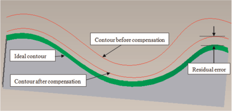
Tool movement path.
Analysis of the tool running path
Position error is still produced when the worktable moves on the guideway after compensation. In the XOY plane,
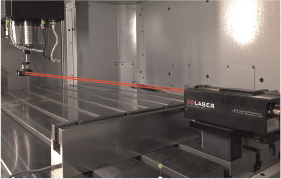
Straightness measurement of the machine tool made by the laser interferometer.
There is a deviation between the actual error value from the controller of the NC machine tool and the measurement error value from the laser interferometer. Here, the measured value was equivalent to the error compensation value. The location relationship between the two points is shown in Figure 3. The actual deviation of the relative position of the cutting tool and workpiece is significant when the measurement value is used as the compensation value. Specifically, these expressions are


Based on the above expressions,


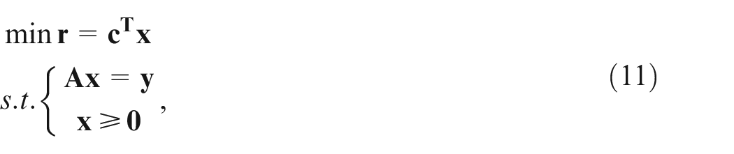
Minimization of r is required in the calculations. This problem can be described in classical mathematics theory as a problem in which r is to be minimized. The significance of this work is that it transforms the optimization method into a linear programming problem to be solved. The simplex method was chosen as the multiparameter optimization algorithm. When the straightness error of the machine tool guide is optimized, the relative displacement between the cutting tool and the workpiece is effectively reduced. Therefore, reducing the fluctuation range of the cutting tool can improve machining precision and processing efficiency.
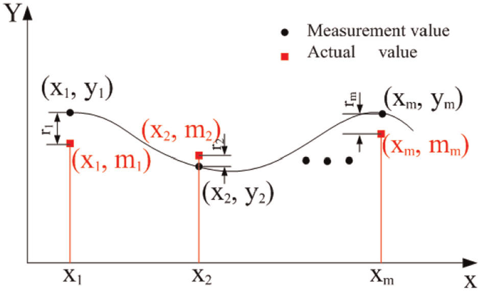
Location relationship between the actual value from the controller of the NC machine tool and the measurement value from the laser interferometer.
Error compensation analysis
The enveloping surface formed between the tool moving path and measuring axis was the smallest. A total of m sampling points on the tool path line were used as the analysis objects after error compensation. The simplex method was used to iterate the objective function to find a group of basic feasible solutions. Analysing the tool path is required to compare the compensation value with the theoretical value. The minimum envelope formed by the measured value and the theoretical value is then selected in the XOY plane, as shown in Figure 4.
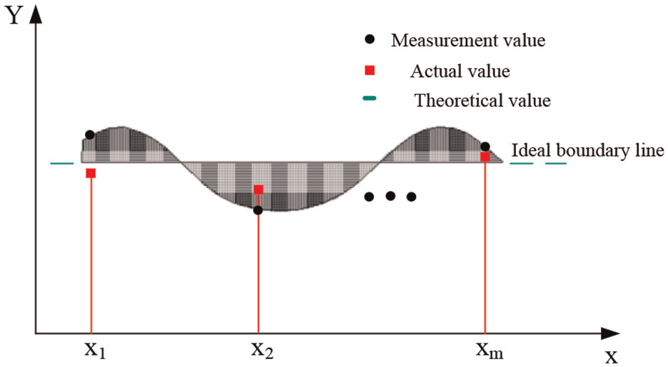
Evaluation of the error compensation value.
The following minimum region equation can be used to describe the region included:

where A, B, and C are the equation coefficients of the envelope area surface. From this, the m sampling points on the plane were measured, and the coordinate values of each point are

The relative position of each point is constructed according to the minimum area method, and the following functions can be obtained:

In the above formula,
The simplex method was used to iteratively solve the objective function, and then the values of
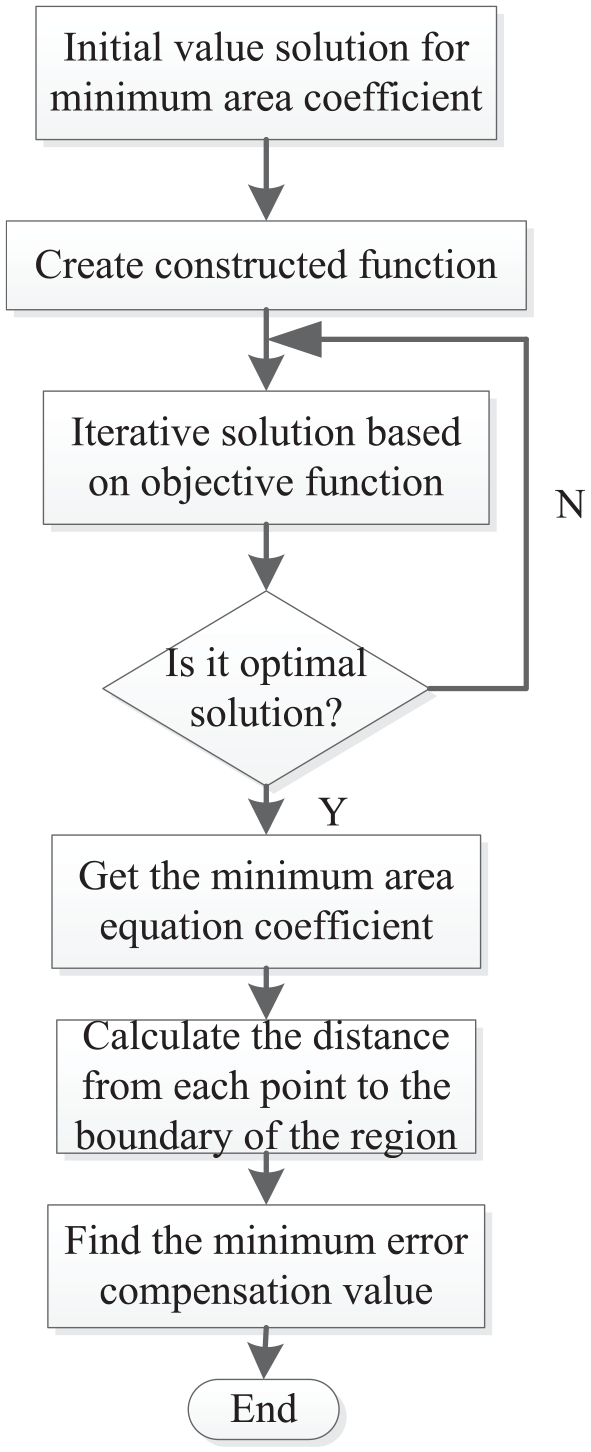
Flowchart using the simplex method to find a solution.
Solution of the objective function
The coordinate points

The constraint condition of the above formula is that the value of
where

Matrix

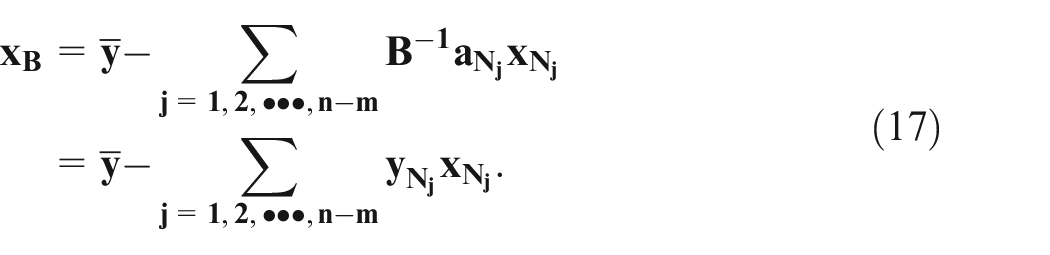
The objective function can be expressed as a non-base variable as follows:
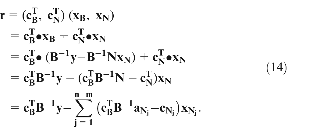
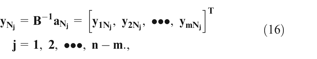
The following expressions are defined:

Therefore, equation (13) can be converted into
If the base variables are
If
If at least one component is greater than 0 in
When
The expression for the corresponding non-base variable
Selecting the base variable was done in a round-robin fashion. The loop is exited when the objective function achieves the optimal solution or when the objective function becomes unbounded. The simplex method was used to optimize the measured values. This prevents the adjacent error compensation data from having a mutation. A set of numerical values obtained by using this calculation method was then conveyed to the compensation module, and the relative displacement fluctuation of the cutting tool and workpiece is minimal after compensation.
Compensation methodology verification and experimentation
The deformation of the guideway will reduce the installation precision of the machine tool and cause a change in the beeline and angular magnitude, which can reduce the manufacturing precision of the machine tool. To measure the tool position and direction before and after error optimization, the measuring paths were corrected to test the straightness error of the machine tool guide. To avoid installation error of the measuring equipment and maintain the same measuring conditions, the running conditions must be identical before and after compensation. The compensation data after error optimization were based on error correction using the software that produced the new NC codes. The movement path of the cutting tool was created based on the tool position file and error information of the machine tool. The actual path of the tool movement was compared with the measurement value repeatedly until it reached the optimal value.
Two types of measurement experiments were conducted to verify the compensation effect. A laser interferometer was used to measure the straightness error of a three-axis machine tool. Through comparative experiments, it was proved that the optimized tool path was smooth.
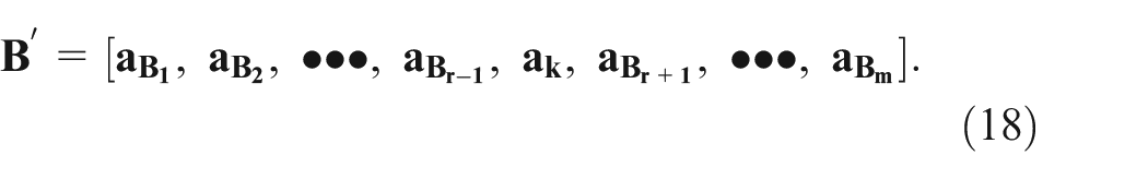
The measurement process was executed under controlled environmental conditions to avoid the influence of random factors. The status parameters of the machine tool were recorded carefully. The path of the tool reciprocating motion was measured to verify the effectiveness of the error optimization. Machine tool errors were measured by a laser interferometer, the positional information of the table was fed into the developed postprocessing software, and then the compensation value was converted to NC codes, which were fed directly to the machine tool. The new NC codes created in this manner were executed in the machine tool, and its movement was tracked using a laser interferometer. Figure 6(a) and (b) show the straightness errors in the Y and Z directions, respectively, when the table moves along the X axis after compensation. The experiment results indicate that the tolerance range of the straightness error
Straightness error of the table moving along the X axis (a) in the Y direction and (b) in the Z direction.
Similarly, Figure 7(a) and (b) show the straightness errors in the X and Z directions respectively, when the table moves along the Y axis after compensation. The experiment results indicate that the tolerance range of the straightness error
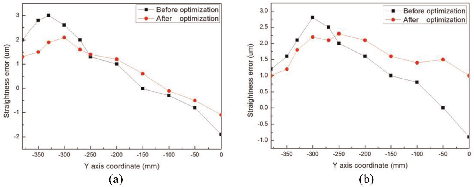
Straightness error of the table moving along the Y axis (a) in the X direction and (b) in the Z direction.
Throughout the straightness measurement results, the error range resulting from the table moving along the X axis or Y axis was reduced after optimization. It is worth noting that the experiment only verified tool fluctuations caused by straightness errors. In fact, other error sources, such as rotation and verticality errors, will also have an impact. A reasonable conclusion can be drawn that the proposed simplex method in this study is a feasible way to optimize error compensation data.
To further verify the effect of data optimization, a profiler was adopted for roughness measurements to identify the surface quality of the machined parts. A practical cutting experiment was conducted using a three-axis machine tool. The specific cutting parameters were as follows: (1) 5 μm for the depth of the cut, (2) 1000 rpm for the spindle speed, and (3) 12 μm/r for the feed rate. The measured surface roughness value was 9.6 μm before optimization and the measured surface roughness value was 4.5 μm after optimization. Figure 8 shows the surface quality of the processed parts. The compensation data that have not been optimized were directly sent to the CNC system, and the cutting track of the machined part surface is obvious, as shown in Figure 8(a). After the compensation data were optimized, the cutting track of the machined part surface became blurred, as shown in Figure 8(b).
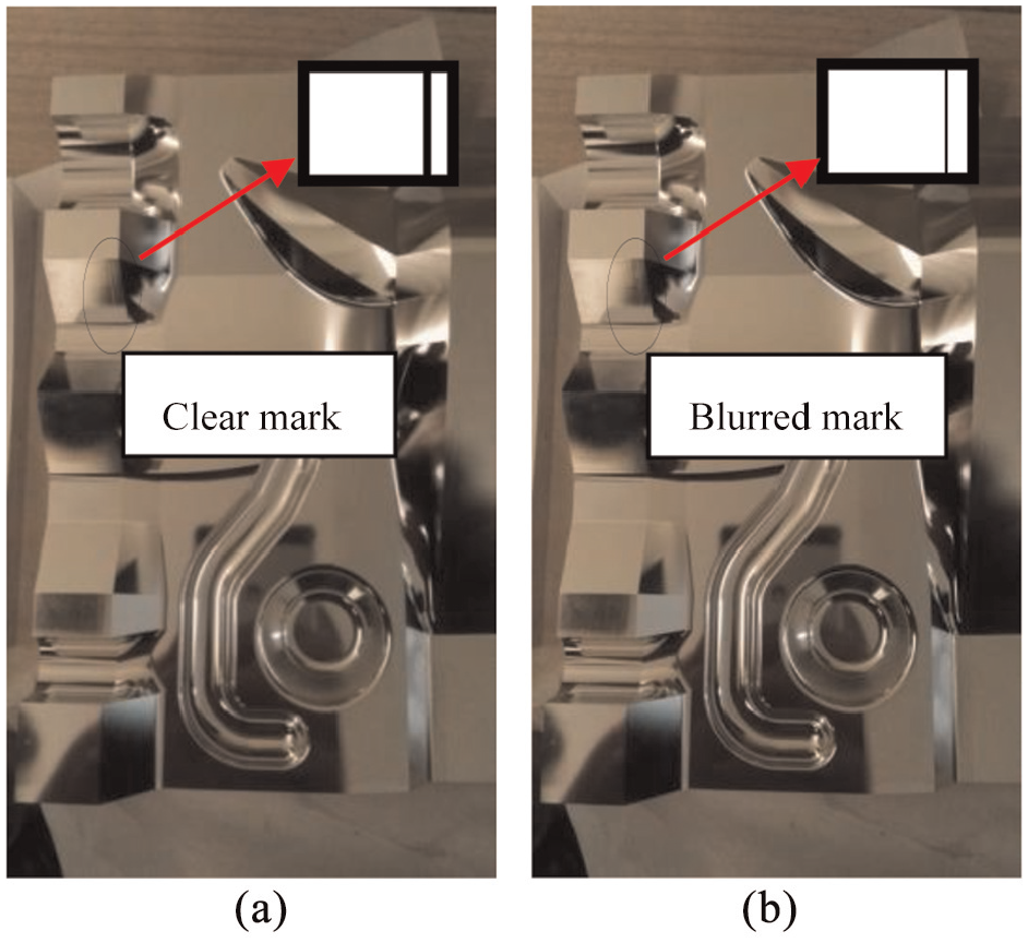
Surface quality of the part machined: (a) clear mark and (b) blurred mark.
The analysis reveals an obvious reduction in the fluctuation range of the tool operation. This demonstrates that the implementation of the method is feasible. Therefore, the compensation data can be optimized based on the simplex method theory, which is a perfect way to reduce tool fluctuation.
Conclusion
A new optimization method for tool path calculation in an NC machine tool was proposed. The proposed method is based on the simplex method of linear programming. The measured value produced by the laser interferometer was not compensated directly. The tool fluctuation range were reduced after the compensation data were optimized. The corrected compensation value was transmitted to the error compensation module, and the position of the tool was calculated. Measurement experiments were executed in a real machine tool to evaluate the mathematical method developed for the optimization of compensation data.
The simplex method has a strong potential advantage owing to its good optimization effect. This algorithm can smoothen the running path of the tool and increase the surface quantity of the workpiece. In addition, no special measuring devices need to be developed. The new approach was implemented in a prototype software system. This technique reduces the tool fluctuation range, as revealed from an examination of the compensating effect using a laser interferometer. Finally error optimization data were verified as being able to efficiently compensate for the straightness error of the machine tool. In addition, the optimization method of error compensation is equally applicable to other types of machine tools. Moreover, a measurement experiment was conducted with the machine under dry running. In fact, vibration, deformation, and other errors will also affect measurement accuracy. A related study should be conducted in the future to further improve the dynamic accuracy of machine tools.
Footnotes
Declaration of conflicting interests
The author(s) declared no potential conflicts of interest with respect to the research, authorship, and/or publication of this article.
Funding
The author(s) disclosed receipt of the following financial support for the research, authorship, and/or publication of this article: Financial support from a National Science and Technology in China Major Project for research on the application of technical specifications in domestic CNC systems (No. 2019ZX04024001) is gratefully acknowledged.