
Abstract
One of the major sources of error in machining operations is the inaccurate positioning of the workpiece in the fixture. Generally, the surface of the workpiece that is in contact with the fixture locators is used as a workpiece reference surface (WRS). Errors in the WRS can lead to improper placing of the workpiece in the fixture and, in turn, to inaccurate machining operations. In this paper, a method is introduced that eliminates the effect of WRS errors on machined features produced in a milling operation. In the proposed method the positioning of the workpiece with consideration of WRS errors is mathematically modelled using homogenous transformation matrices. This model is then used to compensate the effect of WRS errors by modifying the machining toolpath. A post-processing workpiece error compensation module is developed that modifies the initial NC-codes that are generated from a CAM system. The presented method is verified using the simulation software NX and VERICUT and experimental studies. The results confirm that this method can be used to successfully compensate these kinds of errors.
Introduction
There are several sources of error in machining processes, such as machine tool geometric,1–4 thermal5–7 and deformation errors,8–11 fixturing errors12–14 and workpiece reference surface (WRS) errors. The fixturing errors consist of positioning errors and deformation errors. Positioning errors may be due to inaccuracies in the fixture and its elements whereas deformation errors are related to the deformation of the workpiece and fixture under machining and clamping loads. WRS errors can cause inappropriate placing of the workpiece in the fixture and as a result the workpiece can be subject to inaccurate machining operations.
Workpieces usually have two kinds of reference surfaces: design and manufacturing surfaces. The design reference surfaces of a workpiece are those surfaces that are in contact with other components in a mechanism or a machine. Thus, all other features of the workpiece have their dimensions relative to the design reference surface. Also, in the measuring procedure of the workpiece after manufacturing, these design reference surfaces are used as references for inspection purposes.
The manufacturing reference surfaces enable features on a workpiece to be interrelated during machining operations. The machining reference surfaces are used to specify the position of the workpiece relative to the cutting tool and the machining coordinate system. If the machining and design reference surfaces are identical, then the possible errors created by changing the design reference surfaces to machining reference surfaces are minimal. However, often due to design considerations, the design reference surfaces are different from the manufacturing reference surfaces. In this case errors due to this translation may occur. In this paper, the reference surfaces act as manufacturing reference surfaces. In machining operations, the reference surfaces of the workpiece are placed on the fixture locators.
Generally, a workpiece is machined in several operations with a different feature being created in each operation. Normally, the first machined features are used as reference surfaces for machining new features. Thus WRS errors can originate as a result of a raw workpiece or a faulty operation in previous machining stages. These errors can result in inaccuracies in the newly machined features. Therefore, to manufacture error-free parts, the errors of the reference surface should be as low as possible and they must be manufactured accurately in previous operations. However, regarding design considerations, it is not always necessary. Making these reference surfaces accurately, increases the time and cost of the product.
A new method for manufacturing error-free workpieces that can help to decrease the production time and cost is presented in this paper. In this method, the WRSs are mathematically modelled with respect to their errors. Using this model, the necessary homogenous transformation matrices 15 (HTMs) for transforming the machining toolpath to compensate the WRS errors are generated. These HTMs are used in a prepared workpiece error compensation (WEC) module. This module translates the initial machining toolpath via modifying initial NC-codes which are generated from a CAD/CAM system.
The proposed method could be a significant aid to production industries. In these industries, the parts are usually manufactured in several steps. In each step some features are formed on the parts. These features are not necessarily the final features of the parts and are the reference surfaces for machining the final surfaces. If these reference surfaces are machined incorrectly in previous steps, the final features are not machined correctly. Thus, even though these reference features may not be important in themselves or for the functioning of the final part, they are important in the sense that they do provide reference surfaces for final finished parts. Some of these reference surfaces may even be machined and removed completely at some stage of the machining process. The presented method attempts to solve these problems and reduce the cost of production.
In the following sections, the related literature is reviewed. The mathematical modelling of WRS errors and their compensation procedures are explained. Finally, the presented method is verified by performing experimental tests and simulations using the simulation software NX 16 and VERICUT. 17
Review of related research work
There is a relatively sparse literature on the modelling and compensation of WRS errors. Some of the existing literature is focused on the prediction and compensation of force-induced errors in workpieces. Cho et al. 18 presented a compensation methodology for the machining of profile surfaces. Their method utilizes an on-machine measurement system and modifies the machining toolpath and parameters to compensate the errors. Ratchev et al. 19 presented an analytical flexible force model with a finite element model that is used to predict the machining form error of low-rigidity parts. Ratchev et al. 20 also introduced a multilevel error compensation method for force-induced errors in the machining of thin-walled structures. They predicted the part deflection in the machining toolpath and optimized the toolpath to compensate the predicted errors. Wan et al. 21 presented a systematic procedure for the simulation of a peripheral milling process of thin-walled parts. The method was used to optimize the process parameters to achieve high-precision milling. Subsequently, Wan et al. 22 focused on controlling the force-induced errors in milling of low-rigidity parts. They attempted to increase precision while maintaining a desired productivity level.
About the WRS, in the existing literature, only the effects of the WRS errors on the inaccuracies created in machined features have been studied. Estrems et al. 23 presented a technique that was able to identify the corners of a workpiece that could potentially be inaccurate; it was based on fixture and workpiece inaccuracies and uncertainty of the machining process. They predicted whether or not a machined workpiece would be acceptable. Introducing a method for decreasing those inaccuracies would complete that work. Also, Qin and Zhang 24 studied the effect of workpiece position errors, workpiece elastic deformations errors and inconsistent datum errors on the accuracy of machined features. Wan et al. 25 investigated three types of errors, i.e. machine tool, fixture and WRS errors and presented a unified framework that utilized differential motion methodology to model the errors. They applied this approach to systems with adjustable pins; the errors being accommodated by adjusting the locator pins. Shen 26 presented a method for estimating uncertainties due to geometric form errors in WRSs, fixture locating point variations and coordinate measurement errors and their propagation through multistage manufacturing processes. They only studied the errors and did not introduce a useful method for decreasing them. Also, Djurdjanovic and Ni 27 studied the influence of fixture errors, locating datum feature errors and measurement datum feature errors on the dimensional inaccuracies of machined features. Loose et al. 28 investigated multistage machining processes and used HTMs to translate geometric dimensioning and tolerance characteristic of the WRSs to predict machined feature accuracies in subsequent processes. Zhou et al. 29 used a state space model to represent geometric deviations of the workpiece due to the errors of each machining process in multistage processes.
The discussed works are mostly concerned with the problem of predicting whether or not a workpiece is acceptable as a result of various error sources. To the authors’ knowledge no attention has been paid to solving the problem of the compensation and cancelling of WRS errors. In this paper a method for mathematical modelling of the WRSs with respect to their errors and compensating them is presented. Figure 1 is a flow chart of the presented method.
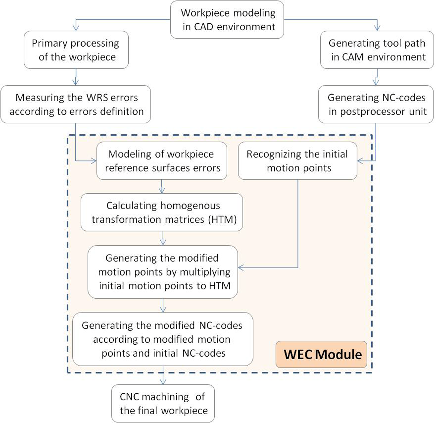
The proposed method for compensating the effect of WRS errors on workpiece features in CNC machining.
Assumptions
The following assumptions are made in the present work.
A general workpiece with three reference surfaces is considered in this work.
The general 3-2-1 principle is used for fixture layout design.
The contact between the fixture locators and the workpiece surfaces are point-surface type.
The surfaces of the workpiece that are placed on the fixture locating system are planar.
The workpiece and fixture elements are rigid; thus deformations due to clamping or cutting forces are not considered.
The errors due to the machine tool and fixtures and other sources are not considered.
Mathematical modelling of the WRS
In this section, the WRS and its errors are introduced and mathematically modelled. Generally, in 3-2-1 fixtures three surfaces of the workpiece are placed on fixture locators. These surfaces act as the WRSs.
WRS errors
For each reference surface three geometric errors are considered; one longitudinal and two angular errors. Since the workpiece has three reference surfaces, it has a total of nine errors.
Three longitudinal errors
Six angular errors
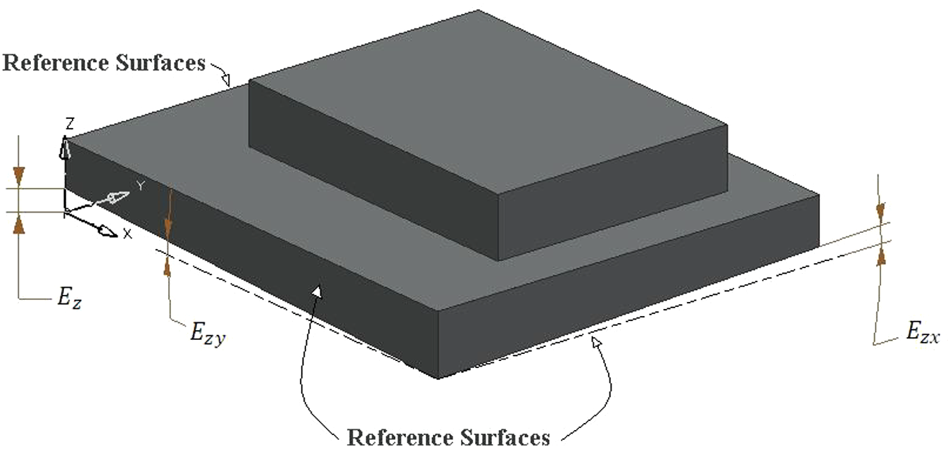
Some errors of the WRSs.
Figures 3(a) and (b) show the accurate and inaccurate positioning of a workpiece in a fixture. In Figure 3(b), the WRSs contain errors and thus the workpiece is placed on the fixture incorrectly.
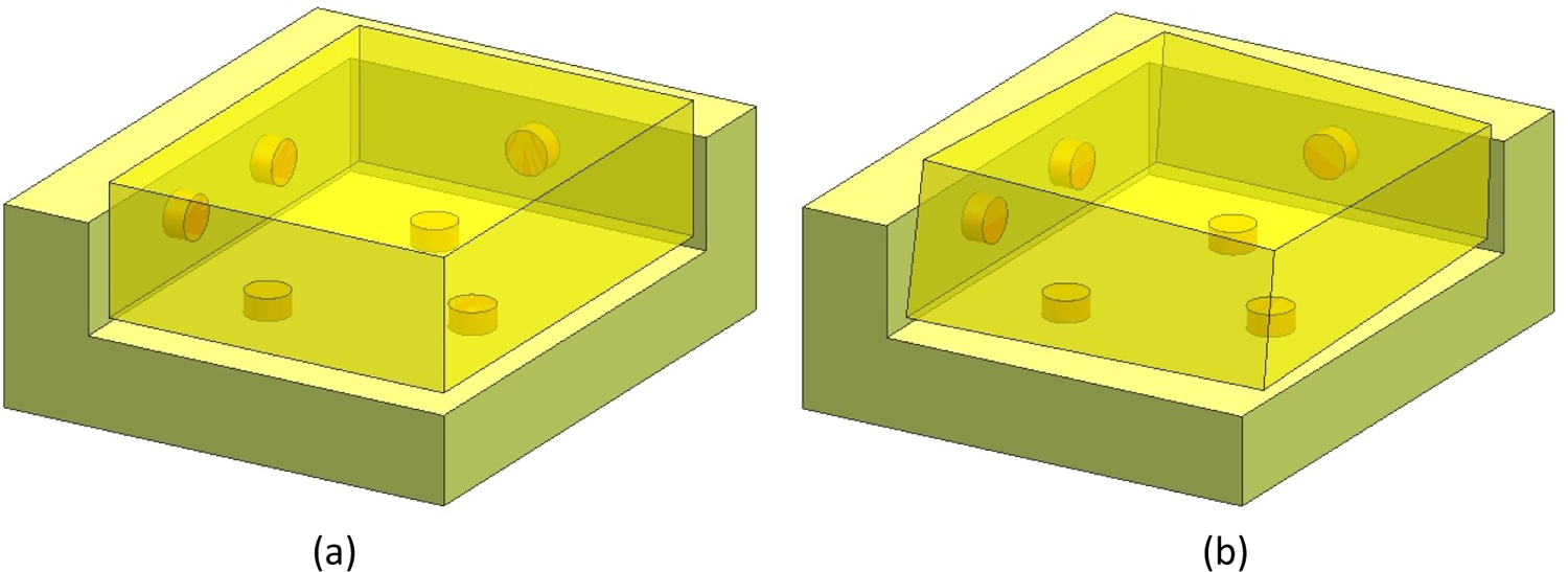
(a) An appropriate placing of the workpiece on the fixture, and (b) an inappropriate placing of the workpiece due to WRS errors.
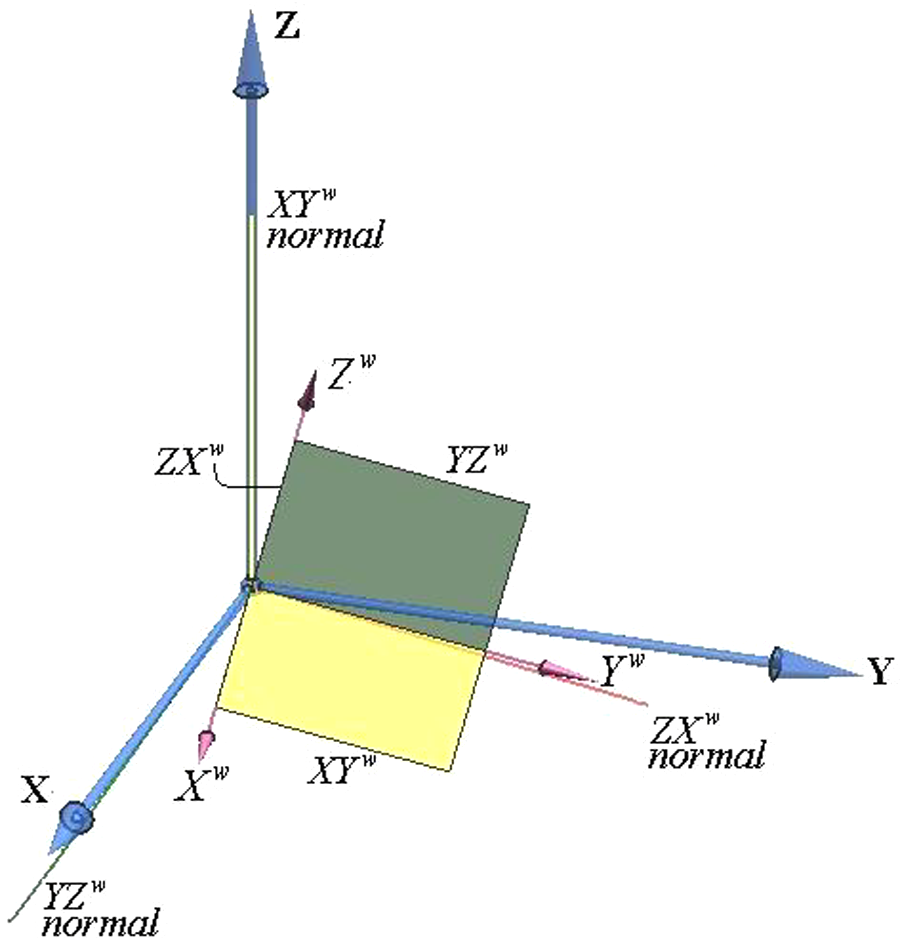
The workpiece and fixture coordinate systems
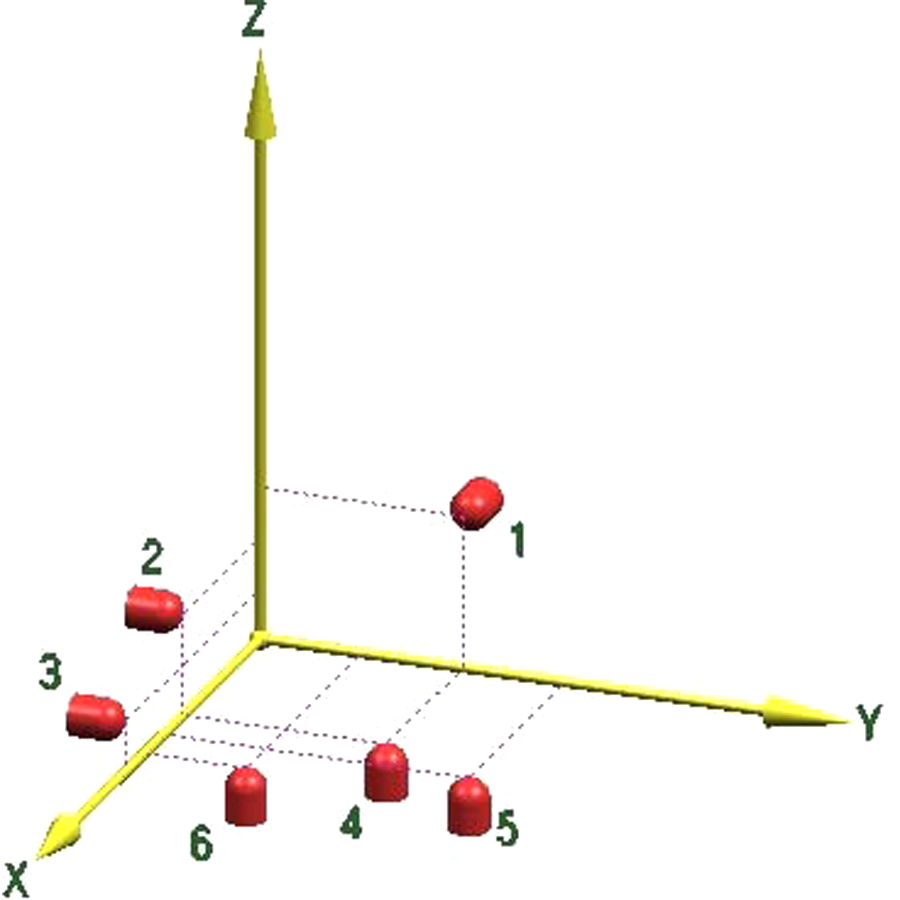
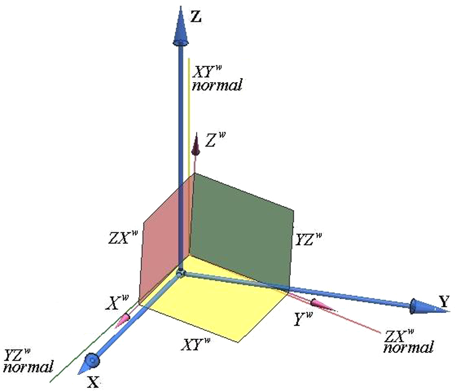
Two coordinate systems are considered in the modelling of the WRS errors: the workpiece coordinate system (WP-CS) and the fixture coordinate system (FIX-CS). In the WP-CS, the coordinate planes are the WRSs. The FIX-CS is the coordinate system of the fixture. If the workpiece has no errors on its reference surfaces, then the WP-CS coincides with the FIX-CS. However, because of reference surfaces errors, generally they are not coincident. As shown in Figure 4, because of WRS errors the WP-CS axes are not perpendicular to each other.
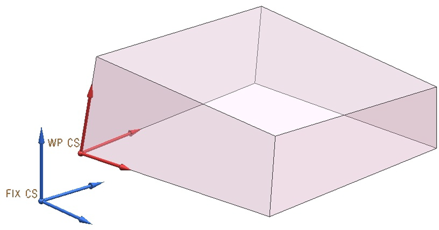
The FIX-CS and WP-CS when the workpiece reference surfaces have errors.
The equations of the WRS
The XY reference surface passes through the WP-CS origin. Because of the three longitudinal errors

Figure 5 shows the normal vector to the XY reference surface and its component angular errors
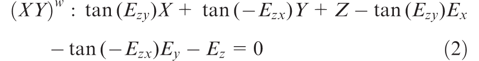
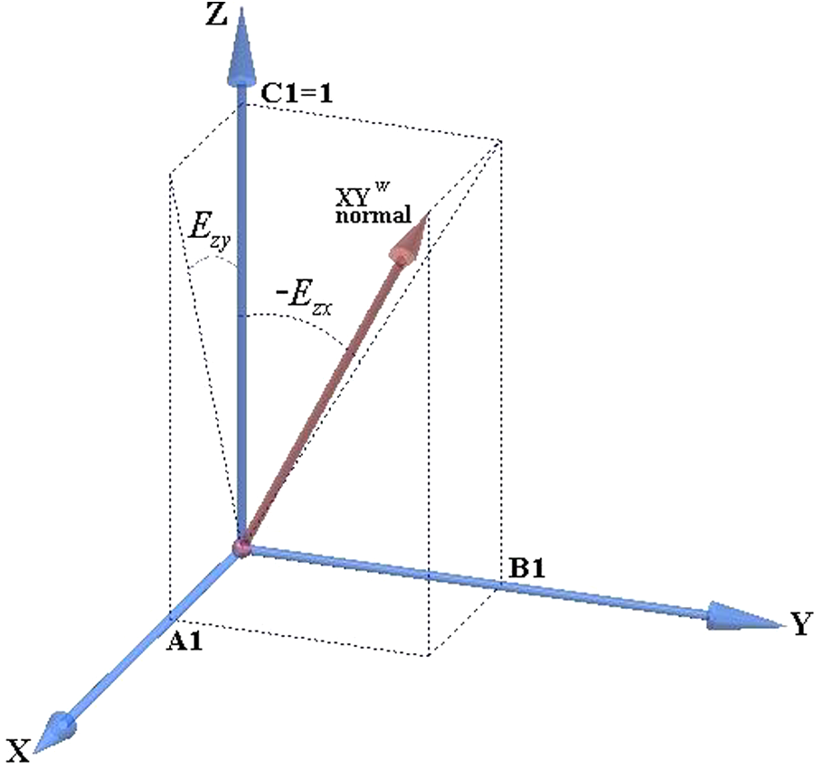
The normal vector to the XY reference surface of the WP-CS and the
The YZ reference surface of the WP-CS
The YZ reference surface plane passes through the origin point of the WP-CS and its normal vector is calculated from the surface angular errors
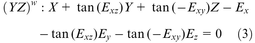
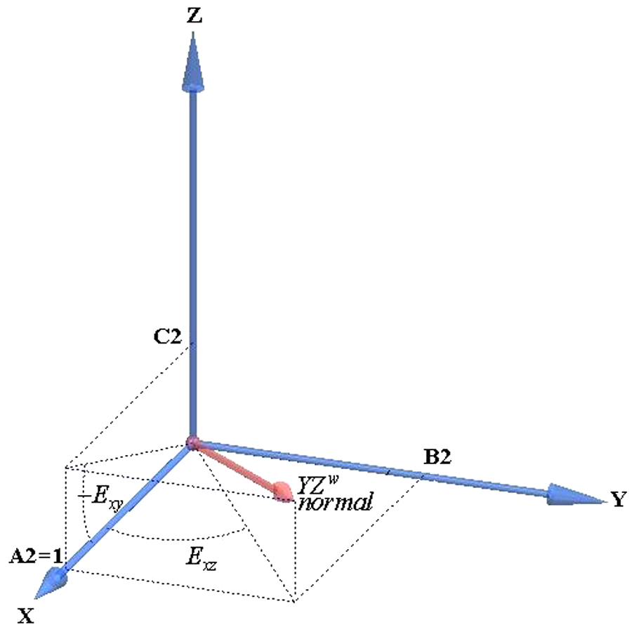
The normal vector to the YZ reference surface of the WP-CS and the
The ZX reference surface of the WP-CS
Similar to the previous cases, the ZX-surface passes through the origin point of the WP-CS and its normal vector is created from the ZX surface errors
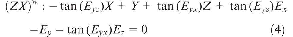
The normal vector to the ZX reference surface of the WP-CS and the
Transformation matrices
If there is no error on the WRSs, the workpiece places on the fixture correctly and the initial NC-codes that are generated from the CAD/CAM system will accurately machine the workpiece. However, if there are any errors on the WRSs, the workpiece will locate on the fixture incorrectly and using the initial codes will result in an inaccurately machined workpiece.
The WRS errors were modelled in the previous section. Now, the HTMs required in order to transform the toolpath from the theoretical position to the actual position is calculated. In actual applications, this transformation is done by modifying the initial NC-codes so that the WRS errors are compensated and the workpiece is machined accurately. The necessary transformations are carried out in four steps.
Linear transformation of the WP-CS origin to the FIX-CS origin.
Placing the WP XY reference surface on the FIX XY-plane by: rotating about the FIX Y-axis; rotating about the FIX X-axis.
Making the WP ZX reference surface tangent to fixture locators 2 and 3 by: rotating about the FIX Z-axis; linear transforming along the FIX Y-axis.
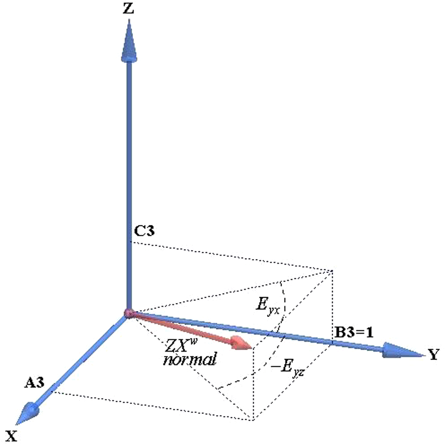
The arrangement of the locators is shown in Figure 8. In this arrangement the tip of locator 1 is on the FIX YZ-plane, locators 2 and 3 are on the FIX ZX-plane and locators 4, 5 and 6 are on the FIX XY-plane.
Making the WP YZ-plane tangent to fixture locator 1 by linear transforming it along the FIX X-axis
The 3-2-1 fixture layout design.
For each transformation, a HTM is obtained and finally, by multiplication of all the HTMs, the total HTM is achieved. Figure 9 shows the initial position of the WP-CS relative to the FIX-CS as a result of the existence of WPS errors.
The WP-CS and the FIX-CS.
Transforming the origin of the WP-CS to be the origin in the FIX-CS
For coincidence of the WP-CS and the FIX-CS, first, the WP-CS origin is moved to the origin of FIX-CS see Figure 10. This transformation allows the three longitudinal errors
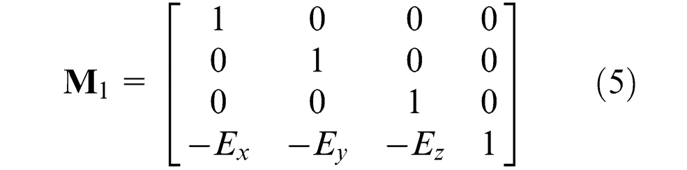
Transforming the WP-CS origin to be the FIX-CS origin.
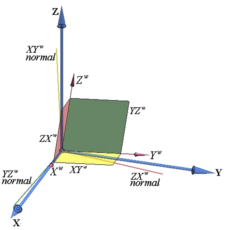
Rotating the WP-CS about the FIX-CS Y-axis
As shown in Figure 11, this rotation is performed using
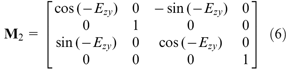
The WP-CS is rotated about the FIX Y-axis by
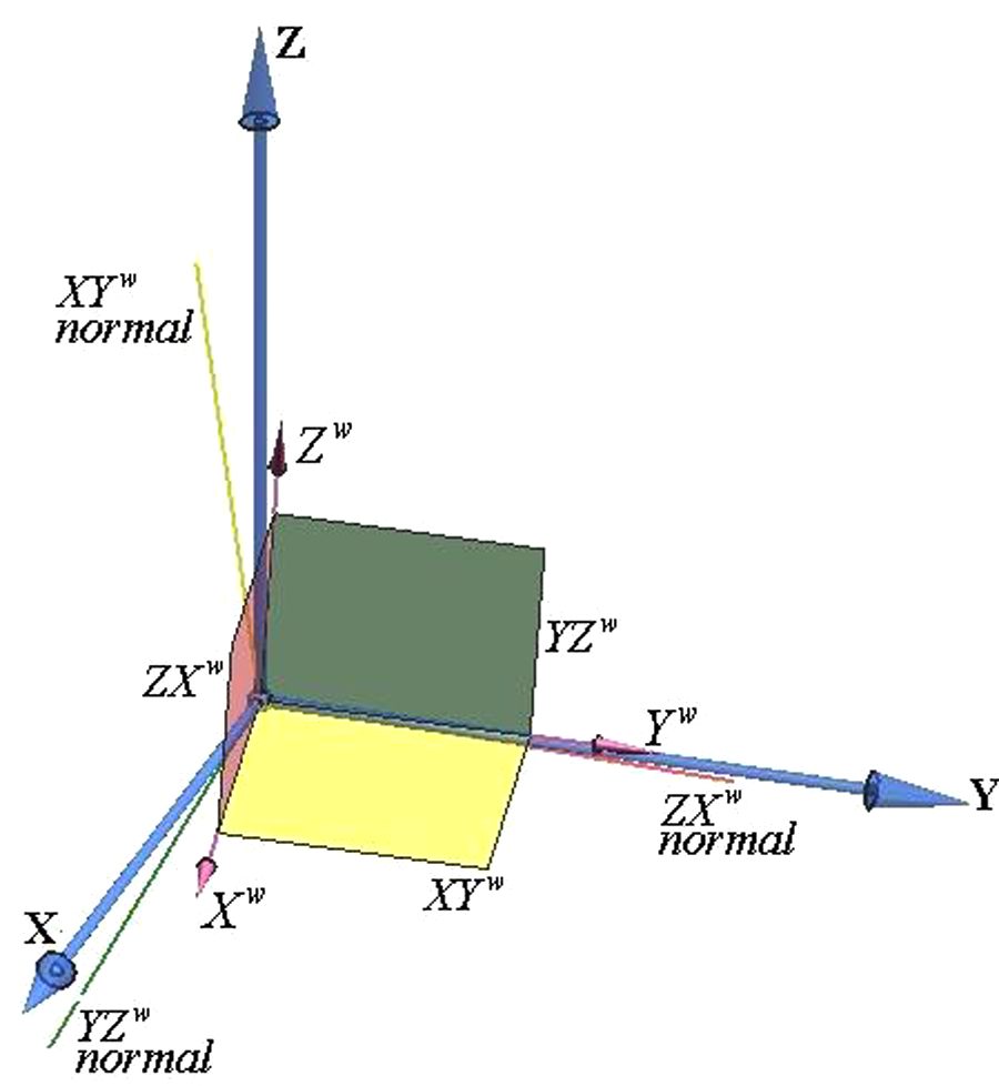
Rotating WP-CS about the FIX-CS X-axis
In this step, the WP-CS is rotated about the FIX X-axis as shown in Figure 12. The rotation angle can be written as
WP-CS is rotated about the FIX X-axis.
where
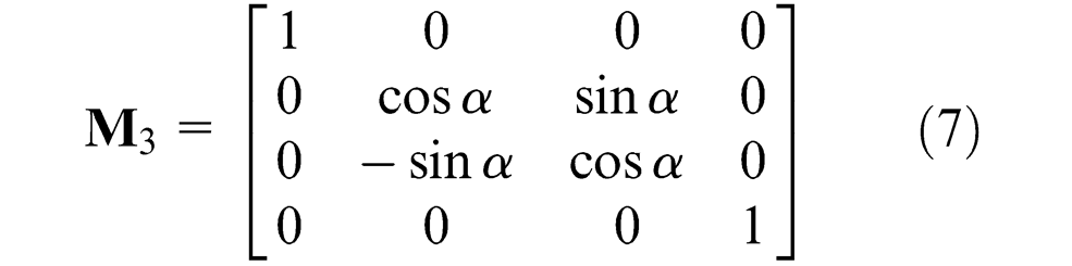
Rotating WP-CS about the FIX-CS Z-axis
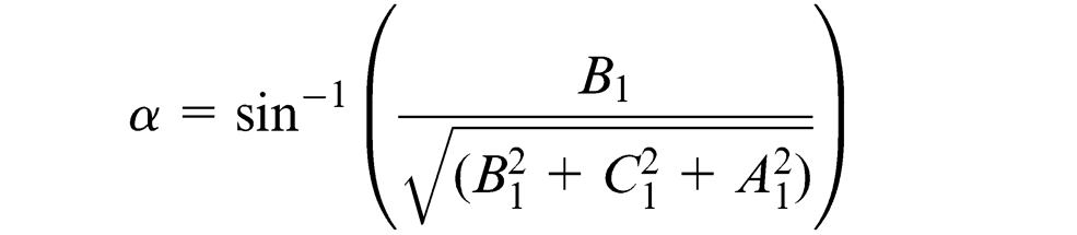
This rotation is performed to make the WP X-axis and FIX X-axis parallel. First, the WP X-axis equation is achieved. This axis is the intersection of WP XY and ZX planes and its equation can be written as
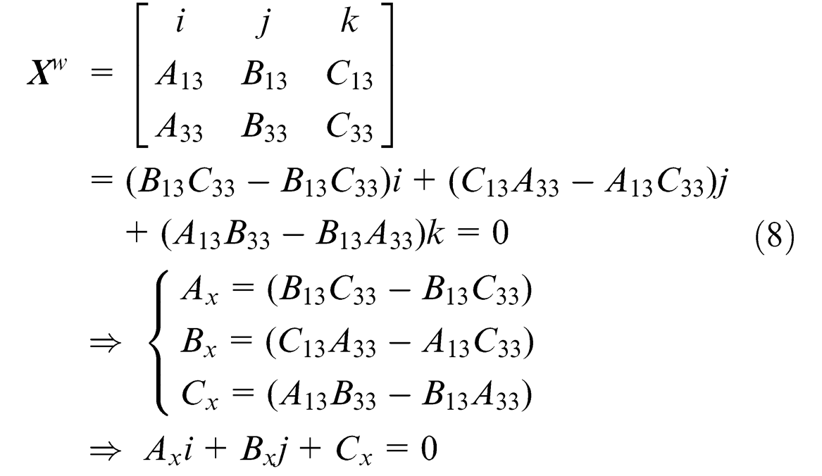
where

The required HTM for the rotation is written as equation (10). Figure 13 shows this transformation.
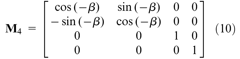
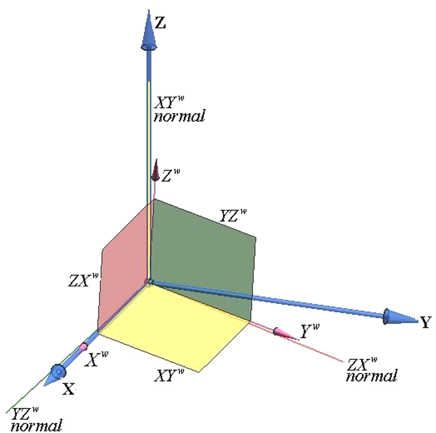
The WP-CS is rotated about the FIX Z-axis by
After this transformation, the WP X-axis is parallel to a line that passes through the tips of locators 2 and 3. However, there is a distance between the tips of the locators and the WP ZX-plane which is eliminated in the next step.
Transformation of WP-CS to the tip of locators 2 and 3
In order to place the workpiece on the fixture, the WP ZX-surface must be positioned tangentially to the tip of locators 2 and 3. In the previous step, the workpiece was positioned parallel to a line passing through those locator tips. In this step, this distance is eliminated by a transformation along the FIX Y-axis. The transformation distance is calculated as follows.

The equation of the WP ZX-plane after the previous transformations is shown in equation (12)

The distance between the tips of locators 2 and 3 and the WP ZX-plane is obtained using equation (13)

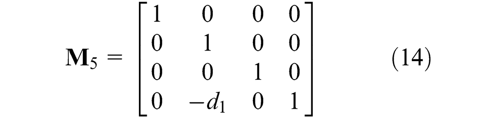
Therefore, the transformation matrix can be written as in equation (14). Figure 14 shows this transformation.
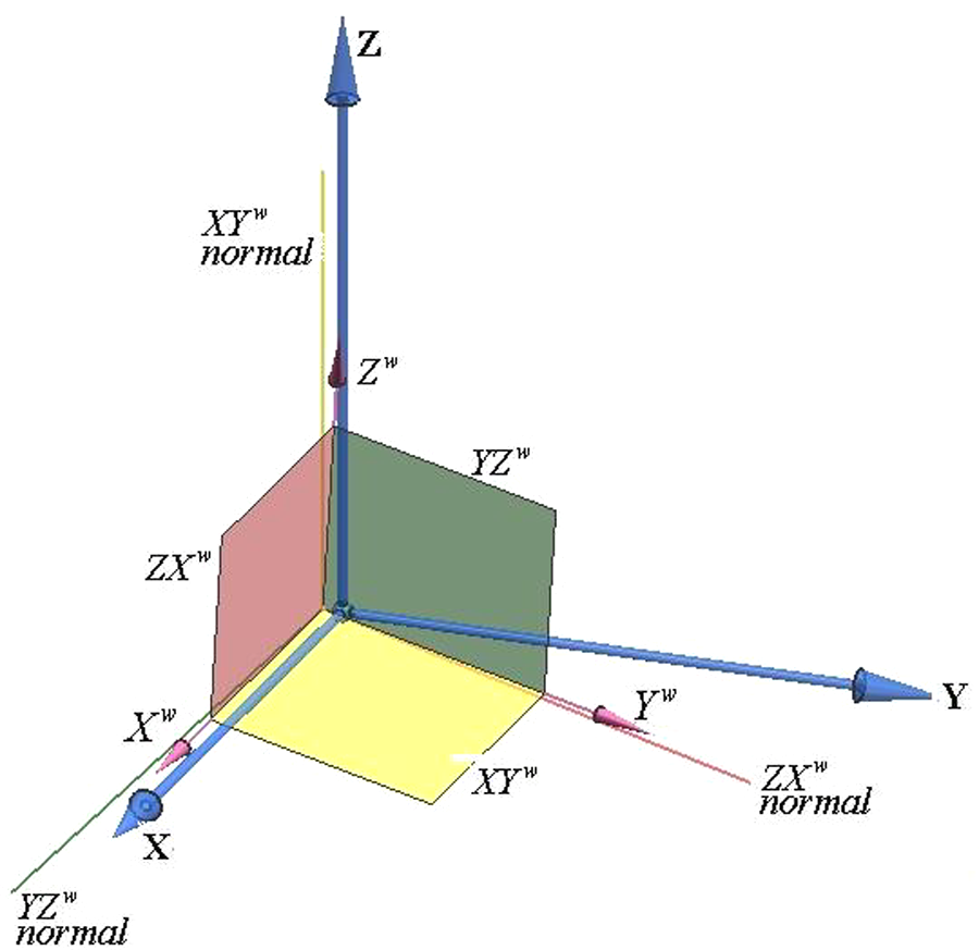
Transformation of the workpiece to the tip of locators 2 and 3.
Transformation of WP-CS to the tip of locator 1
In this step, WP-CS is translated along the FIX X-axis and the YZ-plane of the workpiece touches the tip of locator 1. The distance between them can be calculated using the following expression

The corresponding transformation matrix is written as equation (16). Figure 15 shows this transformation.
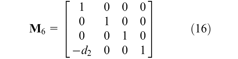
Transformation of the workpiece to the tip of locator 1.
The total HTM
After completing all these transformations, the WP-CS is located on the fixture locators. Multiplication of the six HTMs results in the total HTM

WRS error compensation
In order to compensate the effect of WRS errors on the workpiece machining features, the initial machining toolpath should be transformed using the HTM. In this work the WEC software module is developed for this task. This module is based on the mathematical modelling of the WRS errors and workpiece positioning on the fixture with regards to the errors. The WEC takes the position of the fixture locators and the WRS errors as input and prepares the HTMs. Then, the initial NC-code is inputted as a text file into the WEC module and the modified NC-codes are generated.
Verification
Two case studies are now presented in order to verify the presented method. These cases consider the effects of errors on the WRSs. The free form surfaces of the workpieces are machined using either the initial or the modified NC-codes and the resulting machining errors are compared. In the first case both simulation and an actual machining study are performed whereas in the second case only machining simulations are performed.
Case 1: milling a free form surface
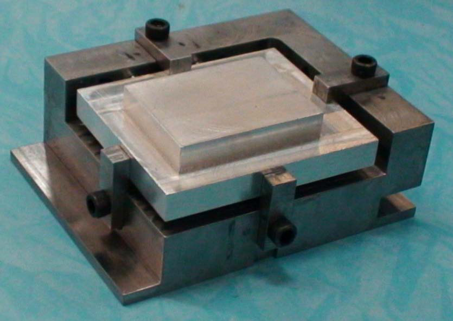
In this case a free form workpiece was machined experimentally and simulations of the process were performed. Figure 16(a) shows the workpiece whose free form surface was machined in the tests. Figures 16(b) and (c) show the blank workpiece housed in the machining fixture. The reference surfaces of the workpiece are shown in Figure 16(b). These surfaces are in contact with six locators as shown in Figure 16(c).
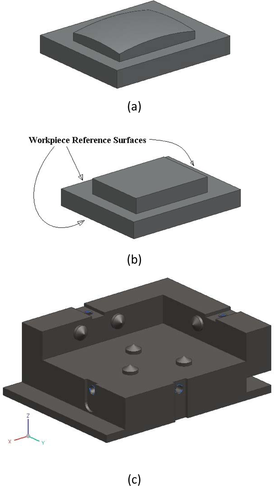
(a) The free form workpiece, (b) the workpiece blank before machining, and (c) machining fixtures.
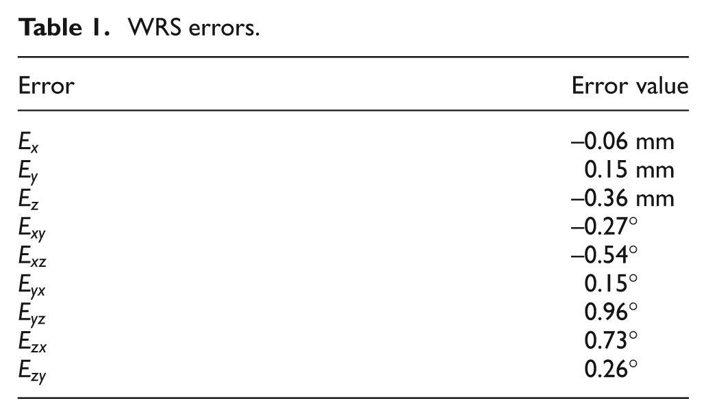
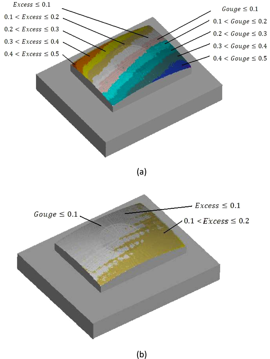
Machining process simulations were performed using NX and VERICUT software. First, a CAD model of the perfect workpiece and the fixture was prepared using NX and initial NC-codes for the machining of the free form surface were generated. Then, a workpiece whose reference surfaces contained errors was modelled. This workpiece was manufactured and the WRS errors were measured using a coordinate measuring machine (CMM) and the results are listed in Table 1. These errors and the initial NC-codes were then inputted into the WEC module and modified NC-codes were generated. Then, a blank workpiece was machined in VERICUT using the initial and modified NC-codes to investigate the effect of the compensation procedure on the accuracy obtained for the machined workpiece. Figure 17(a) shows the global errors for the workpiece surface machined using the initial codes. The excess and gouge errors reach 0.4 and 0.5 mm, respectively. Using the compensation methodology, these errors decrease to less than 0.01 mm as shown in Figure 17(b); this demonstrates that the simulation studies suggest that the proposed method can decrease the machining errors by almost 100%.
WRS errors.
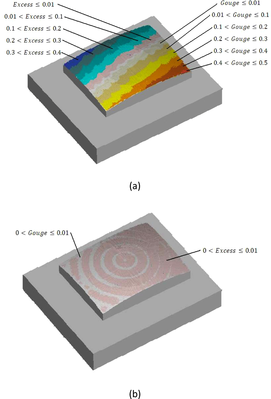
Errors of the workpiece in the machining simulation (a) before compensation, and (b) after compensation.
Machining experiments were performed on a three-axis CNC machine tool. Figure 18 shows the blank workpiece being held in the machining fixture. The WRS errors of the blank workpiece were reported in Table 1.
Workpiece blank in the machining fixture.
Two workpieces with the same errors in their reference surfaces were machined: one without and one with the compensation procedure. The workpieces after machining are shown in Figure 19.
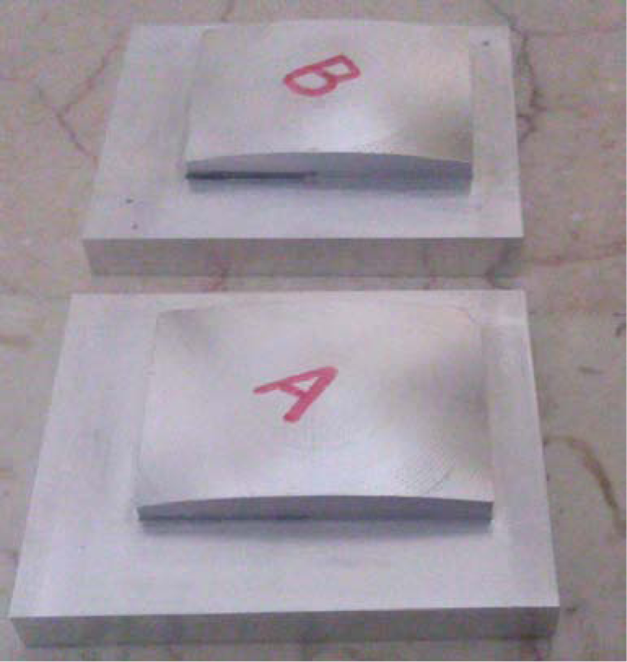
The machined workpieces.
The machined surfaces of the workpieces were measured using a CMM and the results are shown in Figure 20. The global error contour of the machined surfaces was studied. The CMM results were used to prepare the CAD model of the machined surfaces in NX software for comparison.
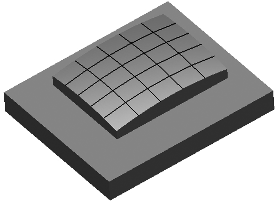
The scanned curves of the machined workpiece.
Figures 21(a) and (b) show the excess and gouge errors of the workpiece surfaces machined using the initial and modified NC-codes, respectively. The results confirm that the method proposed in the present work can considerably decrease the effect of WRS errors on the workpiece. The maximum gouge and excess errors of the machined surface without compensation are about 0.5 and 0.6 mm, respectively. After applying the compensation procedure these errors decrease to 0.2 and 0.1 mm, respectively. The remaining errors are due to other error sources such as for the machine tool, fixture and CMM. According to these experiments, the machined surface errors are decreased by about 60% using the compensation procedure.
Global errors of the workpiece obtained in the machining experiment (a) before compensation, and (b) after compensation.
Case 2: milling a die cavity
The second case studied in this work concerns the machining simulation of the die cavity shown in Figure 22.
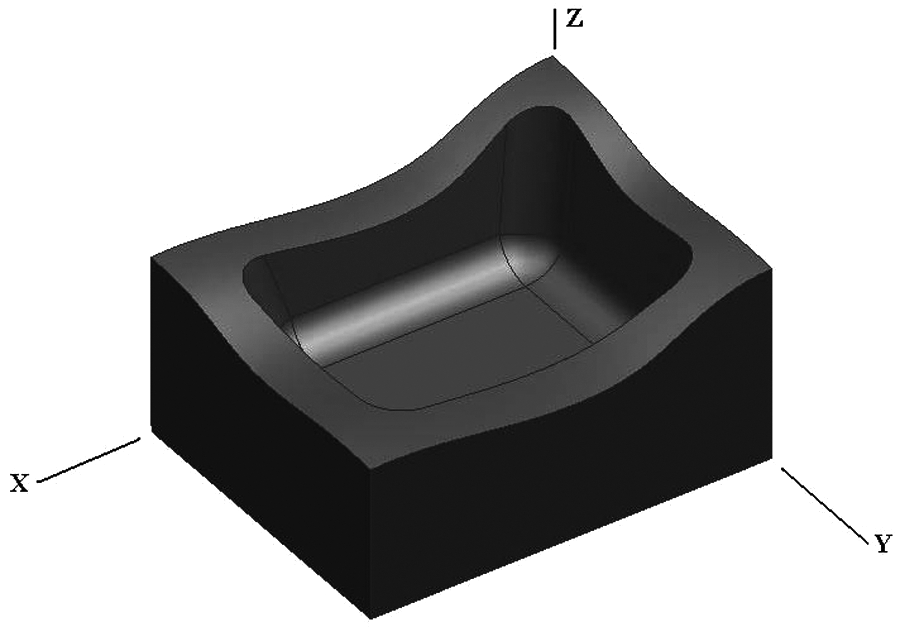
A sample die.
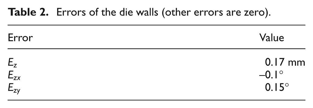
It was assumed that the walls of the die, which are the machining reference surfaces, had the errors listed in Table 2. These errors were created in previous manufacturing operations and were measured before machining the cavity.
Errors of the die walls (other errors are zero).
Machining the cavity using the initial NC-codes generated from CAM software resulted in errors in the machined surfaces of the cavity. Figure 23 shows two views of these errors: the errors reach 0.2 mm.
Two views of the errors in the die cavity.
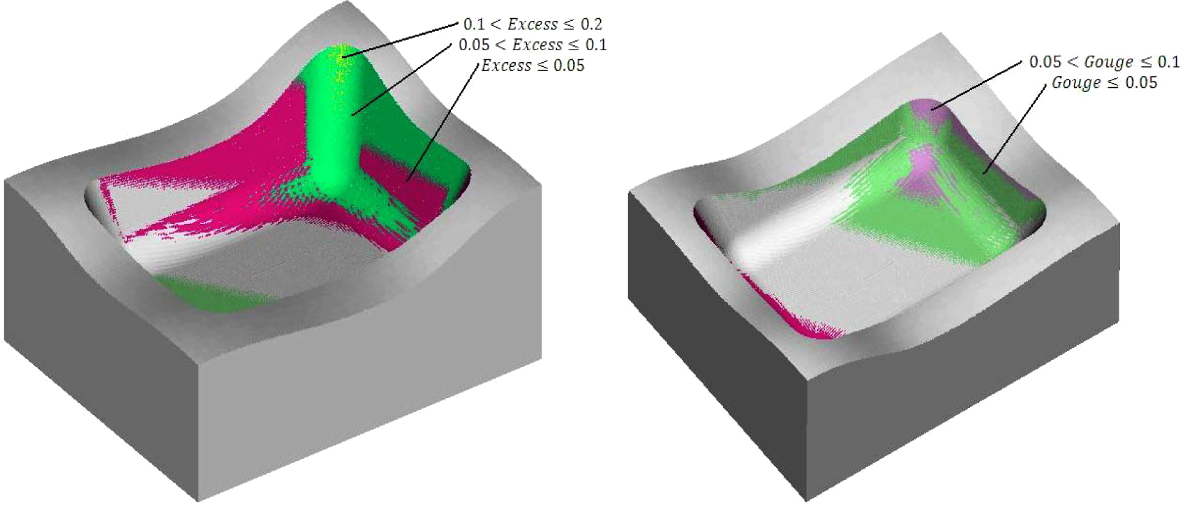
The initial NC-codes were modified using the WEC module proposed in this paper in order to take into account reference surface errors. Machining the cavity using the modified NC-codes resulted in the surface errors for the cavity being considerably decreased. Figure 24 shows the errors that remain after application of the compensation procedure. These errors are less than 0.05 mm and the initial errors decrease by about 75%.
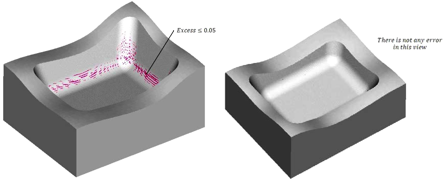
The errors in the die cavity after application of the compensation procedure.
Conclusions
The effect of WRS error on the machining of free form surfaces in three-axis CNC machining has been studied and a method for compensating these errors has been presented. This method is based on a mathematical modelling approach to the workpiece positioning on the fixture that takes into consideration WRS errors. To compensate for the errors the machining toolpath is modified using a HTM to transform the workpiece from its theoretical position to its actual position. Machining simulations and experiments have been performed to validate the proposed approach. The results of experiments show that a significant improvement (of up to 60%) in the accuracy of the machined workpieces can be obtained. This shows the developed method can effectively compensate these kinds of errors, particularly for CNC machining of free form surfaces and cavities. Furthermore, using this method, the production cost and time for the parts is considerably reduced.