
Abstract
Positioning of workpieces in machining operations has a direct influence on the machined features. Workpiece datum errors are one of the error sources that affect the workpiece positioning in the fixture. In this article, a systematic method is presented for eliminating the effect of datum errors on the workpiece machined features in five-axis machining. In this method, the effect of datum errors on the machined features is mathematically modelled using homogenous transformation matrix, and the error vector on the workpiece machining surface is obtained. The error vector consists of position and orientation errors of the tool in workpiece coordinate system. In this work, a compensation module is developed, which is applied to the machining codes of the workpiece. The input to this module is the datum errors and initial NC-codes. The output of the module is the modified NC-codes. For verifying the method, two cases are studied, which are related to five-axis drilling and five-axis free-form milling. Using the compensation method, the position, orientation and form errors are decreased considerably. The results confirm that this method can be used for compensating the datum errors effectively.
Introduction and related research work
Five-axis machine tools have two rotary axes compared with three-axis machines. They are capable of adjusting the tool orientation relative to the workpiece. These machines can be used for complicated workpieces, such as impellers, engine blocks and pump bodies. Recently, lots of attentions have been paid to five-axis machining. Error compensation is a part of interests in this field. Different error compensation methods have been developed for increasing the accuracy of five-axis machining. The most important errors are force-induced, thermal and geometric errors.
The main source of force errors are cutting loads that lead to static and dynamic deflections of the machine tool, tool, fixture and workpiece, which in turn produce incorrect motion of the tool relative to the work. So the features of the work are machined incorrectly. For compensation of static deflection, the deformation values are predicted, and the toolpath is adjusted accordingly.1–3 Wan et al. 4 developed some methods for predicting and controlling the errors in peripheral milling of thin-walled workpieces by selecting the feed rate and depth of cut simultaneously for tolerance specification and maximization of the feed simultaneously. Erdim et al. 5 scheduled the feed rate in order to improve the ball-end milling process to achieve high productivity while maintaining high quality of the parts. Ratchev et al. 6 reported a new methodology for prediction of surface errors caused by deflection during machining of low-rigidity components. The proposed approach is based on the modelling process characteristics that affect part deflection and predicting the workpiece deflection through a finite element analysis (FEA) deflection model and providing an input for downstream decision-making on error compensation.
In the case of dynamic deflections, some attempts were made to select best parameters for decreasing the deflections and instabilities. Tunc and Budak 7 investigated the effects of cutting conditions and tool geometry on process stability in turning and milling through simulations. Wan et al. 8 presented a unified stability prediction method for milling process with multiple delays. The characteristics of delays in milling are analysed by considering the effects of the run-out and the pitch angles of the cutter. Insperger et al. 9 investigated the dynamic stability of the milling process through a single-degree-of-freedom mechanical model. They determined the stability charts and chatter frequencies for partial immersion up- and down-milling operations and for full immersion milling operations.
The thermal errors generally appear due to thermal deformation of machine tool elements. The heat sources are all motions of the machine tool components and the heat generated from the cutting process. Because of these errors, the tool is not positioned accurately relative to the workpiece; hence, some errors are generated on the workpiece features. Both online and offline methods are introduced in the research works for compensating these errors. In online methods, the errors are measured online, and the toolpath is modified accordingly in real time.10,11 In offline methods, the repetitive errors are measured online, and the error model is formed by which the machining codes are modified offline accordingly.12,13
Machine tool components and assembly-related errors cause inaccuracy in machining processes. These are called machine tool geometrical errors. Several attempts are carried out for measuring and compensating the errors. 14 Generally, for compensating the geometrical errors, the machine tool links and joints are considered as a kinematic chain between the tool and the workpiece. The effect of component errors on the relative location of the tool and workpiece is calculated using Homogenous Transformation Matrix (HTM). 15 Subsequently, the error vector is specified in the machine tool workspace. In three-axis machine tools that have linear axes, the error vector consists of positional error. In order to compensate these errors, the tool position is modified. But in five-axis machines, which have rotary axes, the error vector includes orientation error besides the positional error. For compensating the errors in these machines, the machining toolpath is moved along the positional error, and the tool orientation is modified according to the error vector.
In the kinematic chain of the machine tool, the links and joints of the machine axes exist between the tool and the workpiece. By having more attention, it is better to consider the workpiece and fixture as a part of the machine tool kinematic chain. Hence, the errors of workpiece and fixture can affect the relative location accuracy of the tool–workpiece.
The fixtures can imply positional and deformational errors. The fixture positional errors are generally due to geometrical errors of the fixture elements. The deformational errors can be related to the workpiece and fixture deformation under clamping forces. 16 Regarding the fixture positional errors, several research works have been carried out, where in most of them, the effect of errors on workpiece inaccuracy is studied.17,18 In addition, in a number of works, some attempts are aimed at compensation of the errors.19,20
The workpiece errors that are addressed in this article are the geometrical errors of the workpiece datums and are called workpiece datum errors (WDEs) hereafter in this article. The datums are those surfaces of the workpiece that act as references in the machining of the workpiece. In machining operations, the datums are used for placing the workpiece on the fixture or machine table to position the workpiece relative to machining coordinate system. The machining datums of a workpiece are different from its design datums. The design datums of a workpiece are in relation to other parts of an assembly to which it belongs to. However, the machining datums are used for making other features of the workpiece in relation to them.
Since the machining datums are not necessarily the final features of the workpiece, their tolerance limits may be greater than the main features of the workpiece, and even their errors may not be important for quality control of the part. Here, the important thing is the effect of WDEs on the workpiece machined features. As will be discussed in the verification section of this article, the effect of the WDEs may be much more than errors themselves.
In the literature, some attempts are made to investigate the effect of WDEs on the final products. Estrems et al. 18 introduced a method that can anticipate the accuracy of the workpiece before machining it based on the workpiece blank inaccuracies. Qin and Zhang. 21 studied the effect of the inconsistent WDEs on the inaccuracy of workpiece machined features. Shen 22 estimated the effect of geometric errors of workpiece reference surfaces on the uncertainties of the final workpiece. Djurdjanovic and Ni 23 studied the WDEs and their effect on dimensional inaccuracy of the machined features. Loose et al. 24 investigated the cumulative effect of the WDEs on the workpiece final features in the multistage machining processes.
These research works do not suggest a technique for compensating the effect of errors. The simple solution to solve the problem is machining of the workpiece datums more accurately in the previous operation. This solution increases the cost and time of the workpiece manufacturing process. In addition, if the workpiece datums are machined inaccurately in former steps, it is necessary to find an appropriate solution to revive the parts and decrease the scrap parts. For solving this problem, Wan et al. 25 studied the errors of the machine tool, fixture and workpiece datums and presented a method for modelling them. They finally compensated the errors by adjusting the fixture locator pins.
In their previous work, the authors presented a systematic method for compensating the WDE in three-axis machining. 26 In this article, this method is developed further for compensating WDE in five-axis machining. The compensation methodology is different in three-axis and five-axis machining. In three-axis, the compensation procedure is not dependent on the geometrical model of the machine. Generally, in five-axis machining, two rotary axes are active; so the tool orientation, as well as the position, should be modified. In this study, the error vector due to WDEs in workpiece coordinate system (WCS) is obtained, and the initial machining NC-codes are modified according to this vector. The flowchart of the compensation procedure is shown in Figure 1.
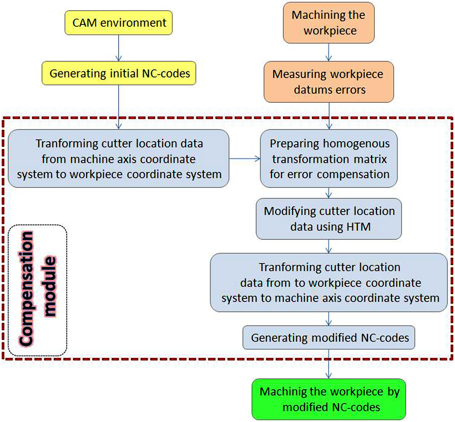
Flowchart of the compensation procedure.
Mathematical modelling of WDEs
For modelling the WDEs, a workpiece with three datums is considered. Other considerations are as follows: the datums of the workpiece are planar and the geometrical form errors do not occur; the workpiece is rigid, so the deformations due to clamping or cutting forces are not considered; and other error sources such as machine tool and fixture errors are also not considered. Figure 2 shows the workpiece with its datums.
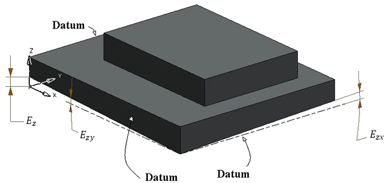
Workpiece reference surfaces and some of its errors.
For each datum, three geometrical errors are considered: one positional error and two angular errors that are named as Eij (i, j = x, y and z). For example, the positional error of the XY plane is shown as Ezz and its angular errors about X-axis and Y-axis are shown as Ezx and Ezy, respectively. These errors are shown in Figure 2. The total number of errors for a workpiece with three reference surfaces is nine.
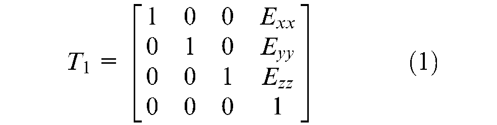
Regarding the WDEs, two coordinate systems (CSs) can be considered: theoretical coordinate system (TCS) and actual coordinate system (ACS). Ideally, the workpiece is positioned on TCS, but due to WDEs, the workpiece moves from TCS to ACS and its datums are identical with ACS planes. In error compensation procedure, the tool location should be transformed from TCS to ACS. For simplifying the calculations, the transformation matrix from ACS to TCS is calculated and then the result is reversed. The transformation from ACS to TCS is carried out in four steps as follows: 26
Step 1
Linear transformation of TCS origin to ACS origin. The transformation matrix is as given in equation (1)
Step 2
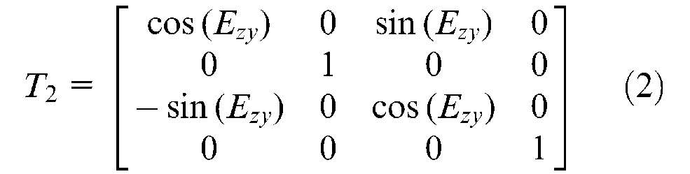
Placing ACS-XY plane on plane TCS-XY by
Rotating about the TCS Y-axis with equation (2)
Rotating about the TCS X-axis as given in equation (3)
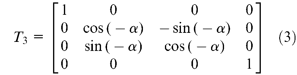
where
Step 3
Posing ACS-ZX plane on TCS-XY as follows: 26
Rotating about the TCS Z-axis using equation (4)
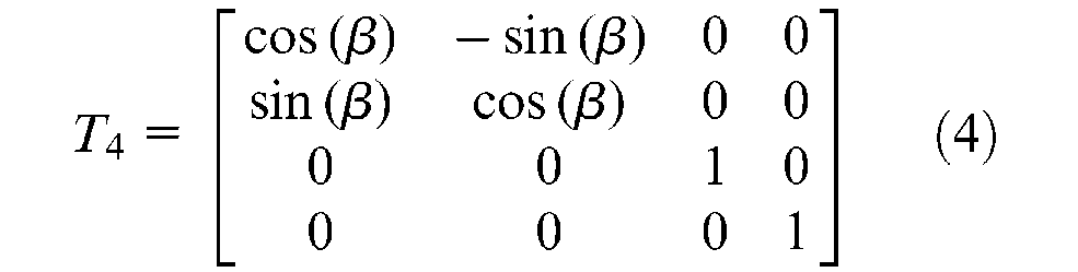
Because of the previous transformations, the angle of rotation
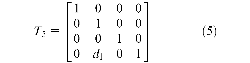
Linear transformation along the TCS Y-axis with equation (5)
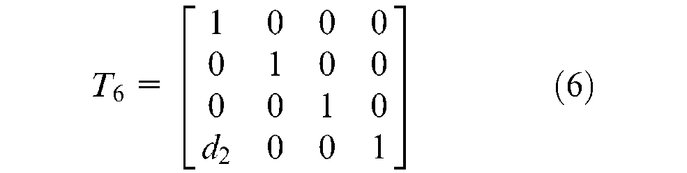
Step 4
Positioning ACS-YZ plane on TCS-YZ by linear transforming along TCS X-axis. The related HTM is as given in equation (6)
where


So the error vectors are achieved as given in equation (9)

where

In the compensation procedure for five-axis machining, the initial tool position and orientation in the WCS are obtained from NC-codes using forward kinematics. 27 The compensated values are then calculated using error vectors. Finally, the compensated NC-codes are generated using backward kinematics.
Kinematic of five-axis machine tool
In the five-axis machine tools, two spaces or CSs can be considered: WCS and machine tool axes coordinate system (MCS). In WCS, which is related to computer-aided design–computer-aided manufacturing (CAD-CAM) environment, the tool position and orientation are determined relative to the WCS as given in equation (11)

Generally, in CAD software, the workpiece and fixture model is created and then the CAD model is sent to CAM module. In the CAM environment, using the machining strategies, the toolpath is generated. The toolpath contains cutter location data, including tool position and orientation in WCS. For machining the workpiece, the cutter location data should be converted into the controller format regarding the machine axes configuration. In three-axis machining, this is simple due to the lack of rotational axes. But in five-axis machine tools with rotary axes, converting cutter location data from CAM system to MCS is more complicated. This task is done using backward kinematic transformation. However, forward kinematic transformation is used for transforming data from MCS to WCS. In the present work, for a five-axis machine tool with axes arrangement of TTTRR, 28 the kinematic modelling of the machine is performed.
Figure 3 illustrates the configuration of the five-axis machine tool used in this study. As shown, the workpiece is placed on the rotary table C, which is mounted on a tilting axis A. The A-axis is mounted on the linear X-axis, which is placed on the linear Z-axis. The Z-axis slide moves vertically on its link, which is bolted on the machine base. However, the tool is fixed on the spindle, which is mounted on the Y-axis. This axis is also placed on the machine base.
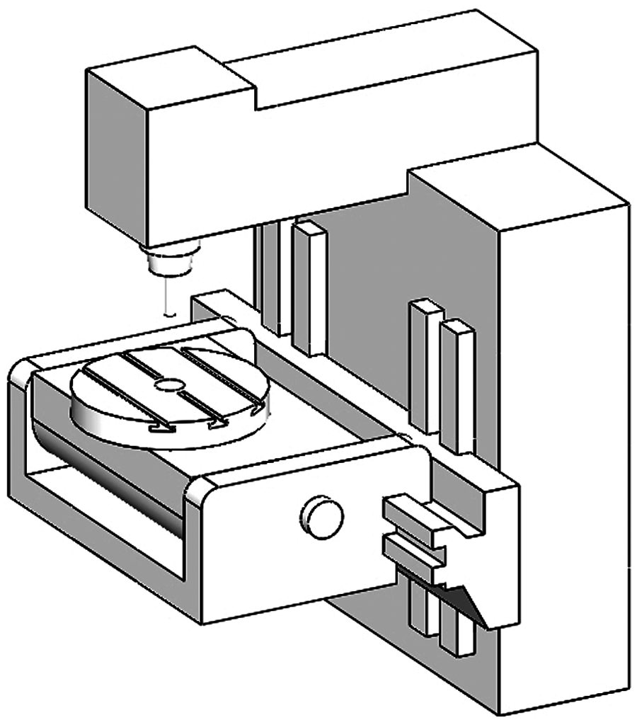
Five-axis machine tool with Z′X′A′C′Y axes configuration.
Figure 4 shows the CSs connected to links and slides of the machine axes in the home position. In a five-axis machine tool, there are five links and five slides, and a CS is assigned for each of them. A CS (r) is considered as the reference system. A separate CS is also considered for workpiece and tool. The parameters
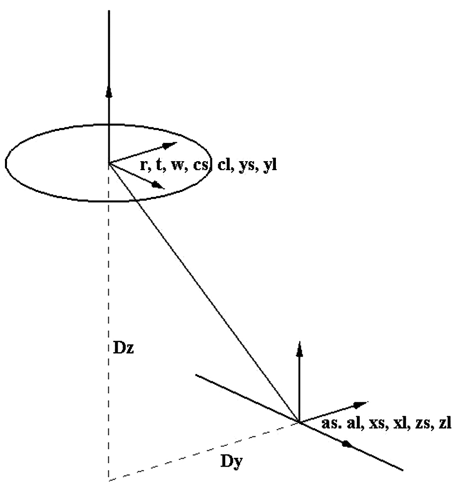
Coordinate systems of the machine tool in home position.
Figure 5 shows the CSs when the machine axes move to the extent X, Y, Z, A and C. Regarding the axes displacements, the transformation matrix from machine tool CS to WCS is obtained as given in equation (12)
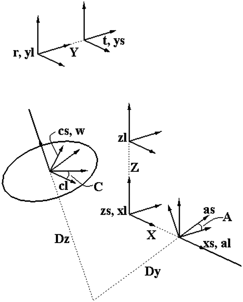
The coordinate system after axes displacement.

Matrix

Since the workpiece is fixed on the table C (C-slide), we have

Since the movement of the tool is the base for determining the direction of the CSs and the table C carries the workpiece, the minus sign is used for the value C. Equation (15) describes the transformation from table C to table A.

The A-slide rotates about A-link as
On the other hand, the transformation from tool CS relative to the reference CS is determined as given in equation (16)


Since the CS of Y-link is attached to the reference CS so

By multiplying all matrices, the transformation from the tool CS to the WCS is obtained as given in equation (19).
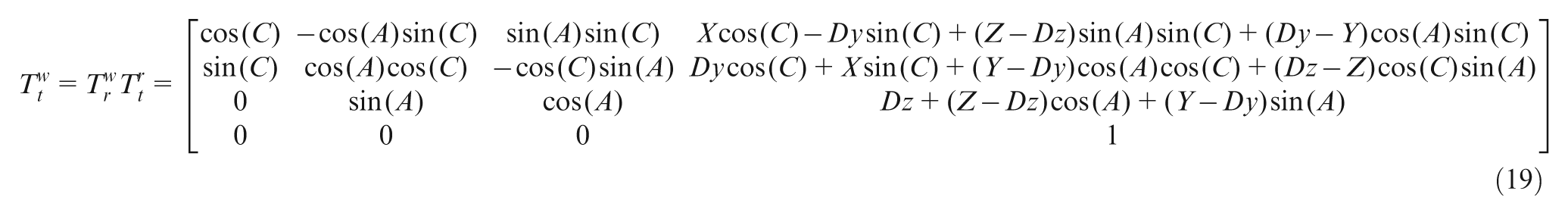
Using this matrix, the tool position and orientation vector in the WCS is calculated as given in equation (20).
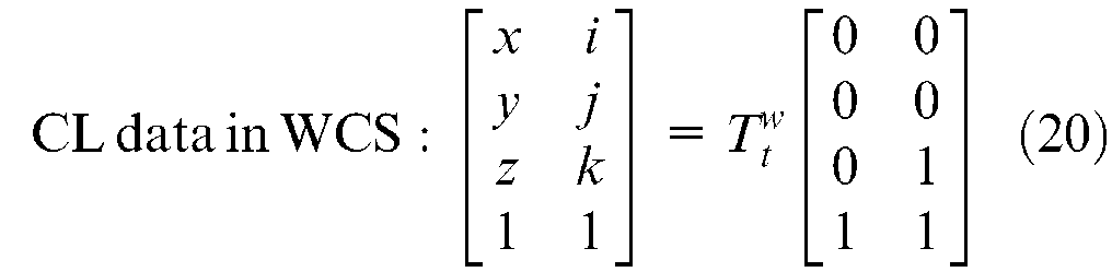
Thus, the equations of cutter location data in the WCS are as given in equation (21).
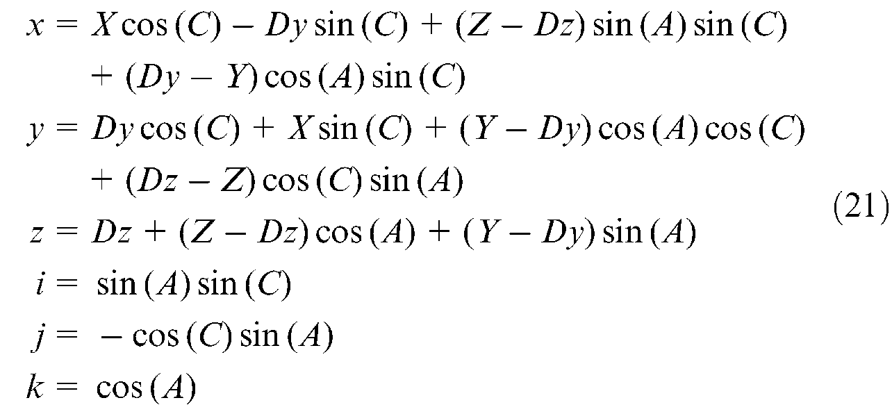
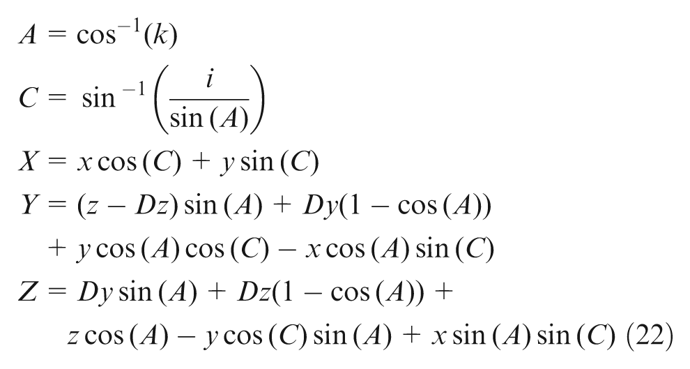
The above results are achieved from the forward kinematic approach. Using these equations, the tool position and orientation vector in the WCS are generated from the NC-codes in the MCS. For compensation of WDEs, these vectors are transformed according to the error vector (equation (11)) and the modified tool location data are obtained. The modified data should be transformed to the MCS to generate the modified NC-codes. For this transformation, the backward kinematic equations are required. These equations are derived from the forward equations as given in equation (22)
WDE compensation
In order to compensate the WDE effect on the workpiece machined surface, the workpiece error compensation (WEC) module used in Fallah and Arezoo 26 is further developed and applied in the present work. This module takes all WDEs, initial NC-codes and five-axis machine tool configuration as input and generates the modified NC-codes.
Verification
For verifying the method, two cases are studied, which are related to five-axis drilling and five-axis free-form milling. In each case, some errors are considered on the workpiece datums. The workpieces are machined using initial and modified NC-codes, and the accuracies are compared. In one case, both machining simulation and experiment are carried out. In another, the machining simulations are only performed. In this section, all of the simulation and experimental verifications are explained. The machining simulation are carried out using NX 29 and VERICUT 30 software.
Case 1: five-axis drilling
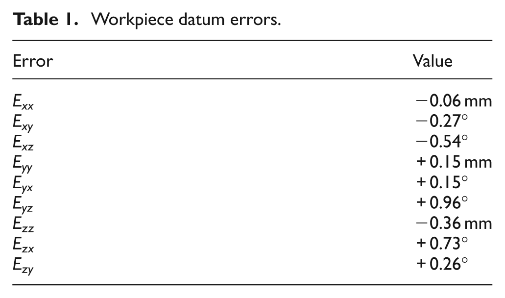
This case is studied in experiment and simulation. At first, the blank workpieces are machined, and the datum errors are measured as shown in Table 1.
Workpiece datum errors.
Simulation
The CAD model of the workpiece with 12 holes (Figure 6) is prepared in NX and the initial NC-codes for drilling the holes are generated. The holes have different orientations, and a five-axis machine tool is considered for making them.
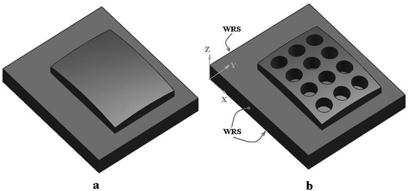
(a) Blank workpiece and (b) final workpiece with its reference surfaces.
Moreover, a workpiece with its errors in its reference surfaces is modelled. This workpiece with datum errors is machined in VERICUT using initial and modified NC-codes. The modified codes are generated from the WEC module according to the WDEs. The position and orientation error of each hole are measured. Figure 7 shows the errors before and after error compensation. As the result shows, the presented method can effectively compensate the workpiece reference surface errors.

Orientation and position errors of machined holes (simulation).
An important point to mention here is that the machined workpiece positioning errors can be greater than the source position errors because of angular errors. So even if the workpiece datums are created precisely, there is no guarantee for accurate machining of the workpiece. The present method is useful for such cases and can decrease the cost of process.
Experiment
Machining experiments for this case are carried out on a Hermle C800u five-axis machine. Some errors are applied on the workpiece datums and measured using a CMM as shown in Table 1. Figure 8 shows the machined workpieces with and without compensation procedure.
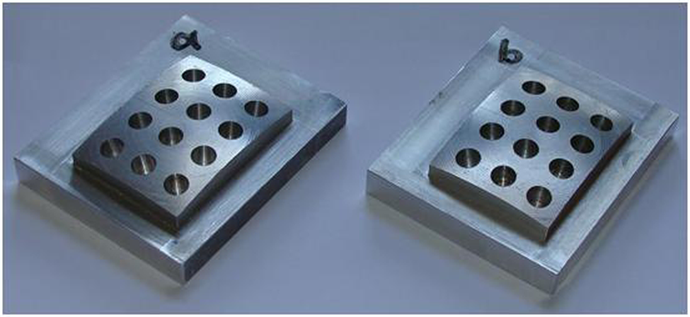
Machined workpieces with and without compensation procedure.
The orientation and position of the drilled holes are measured. Figure 9 shows the orientation and position error of 12 holes before and after compensation. Using the compensation procedure, the results show that the effects of datum errors are decreased considerably. It should be noted that the remaining errors may be due to other error sources, such machine tool, fixture, deformation, measuring, vibration and so on.

Orientation and position errors of machined holes (experiment).
Case 2: five-axis free-form milling
The machining of a blade aerofoil (Figure 10) is also investigated in the present work. The blade has twist and so it should be machined on a five-axis milling machine.
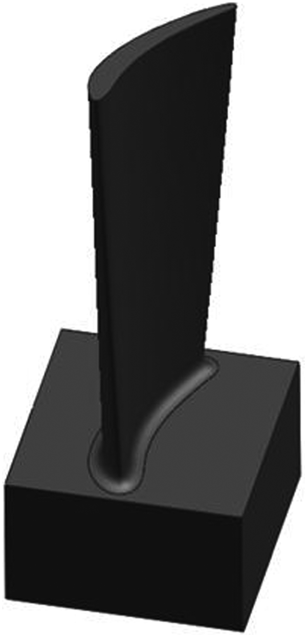
The blade aerofoil.
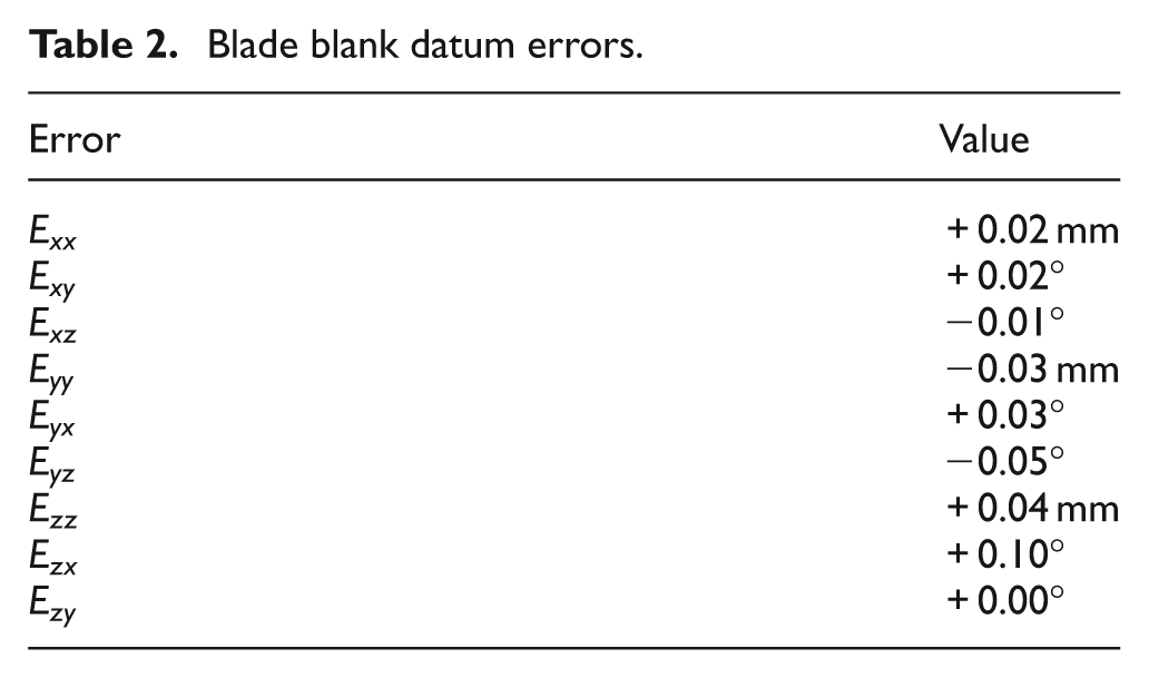
The datum errors of the blade blank are given in Table 2. The initial NC-codes are generated using the CAM software.
Blade blank datum errors.
WEC module is used for generating the modified NC-code according to the datum errors. The blade is machined in the simulation software using initial and modified NC-codes. Figure 11 shows the form errors of the machined surfaces in two views before and after compensation. The results show that the initial errors are about 0.3 mm, and after compensation procedure, the errors reduce considerably to about 0.03 mm.

Form errors of the aerofoil machined with (a) initial NC-codes (b) modified NC-codes.
Conclusion
In this article, a new method is presented for compensating the effect of WDEs in five-axis machining. This method is based on the mathematical modelling of WDE effects on the workpiece machined features. Using the HTM for transforming the workpiece from its theoretical position to actual position, the tool position and orientation in NC-codes are modified to compensate the errors. For verifying this method, two cases are studied, which are related to five-axis drilling and five-axis free-form milling. According to verifications, using the compensation method, the position, orientation and form errors are decreased effectively. The results show an effective improvement in the accuracy of the machined workpiece. Furthermore, using this method, the production cost and time required for the various parts can be reduced considerably.