
Abstract
In this paper, we proposed a new device for geometry errors measurement and coaxiality evaluation, and the corresponding methodology for coaxiality evaluation from measurement data is presented, which allows to characterize multiple holes at a time. Unlike traditional measurement system a laser sensor is mounted onto out of the holes so that multi-hole surfaces can be “seen” by the senor when it rotates around a fixed axis. First the intersections (or ellipse profiles) of the sensor’s scanning plane and holes, are computed by fitting. Then, the center coordinates and profile points of the ellipse are computed and transformed to the 3D global coordinate frame. Finally the centerline of the hole is determined from the 3D profile points by using a weighted least-squares fitting algorithm. In addition, to reduce the effect of noises on the measurement result, error analysis and compensation techniques are studied to improve the measurement accuracy. A case study is presented to validate the measurement principle and data processing approach.
Introduction
Accurate measurement is a crucial step for work piece tolerance verification, which deals with roughness, geometry and form measurements. There are a large number of measuring instruments have been developed.1–5 According to measuring principles, the measuring instruments can be categorized by sensors into tactile and non-contact measurements. Tactile measuring instruments like Coordinate Measuring Machines (CMM), enable highly accurate measurements within the context of dimensional inspection, and have been widely applied in industries.1,2 However they are limited in terms of measuring speed, measurement point density and the measurement of complex surface microstructures and unsuitable for on-machine measuring due to high requirements in work environment. Most of non-contact sensors are based on the principle of optical triangulation measurement due to the ease of use, an adequate integration and a lower cost, and a growing number of optical sensors are used in various applications. Other non-contact sensors also are applied for specific case, for example, ultrasonic sensor often is used to measure the wall thickness from the outside of the workpiece. Ultrasonic sound measuring instrument with high-performance laser guiding system was developed to measure the center deviation during the process 3 ; 2D laser-ultra sound tomography was proposed to measure piece wise linear surface profiles. 4 The disadvantage is the ultrasonic systems susceptibility toward the rough environment and unsuitable for high precision measurement cases. Nonetheless a major drawback of the non-contact measurement instruments is that measurement uncertainty is unknown, and depends on the surface properties and measuring strategy, 5 and many optical measuring instruments such as white light interferometer, structured light, and focus variation can be used only for measurements orthogonal to the surface for roughness measurement or measurement of small distances.6,7 Fortunately, high speed and accuracy can be achieved by using laser sensor through a scanning sampling process, which have achieved a good level of confidence in the reverse engineering field.8,9 In addition, a inline measurement method for additive manufacturing was presented by a robot with a laser sensor, in which a path planning algorithm is developed for digitizing additive manufacturing parts at a given quality of the resulting cloud of points to ensure the quality to measure the shape deviation. 10
Since the laser senor is integrated with light source and is large in size it is unsuitable for measuring small hole. Therefore little research work has been conducted on the measurement of holes, in particular the cases with high precision requirement. In recent years, there is a great progress in laser measurement technology. A point profile can be obtained at a time for the updated laser sensor instead of the traditional a point. It is advantageous to the measurement of geometric error of manufacturing features. The features such as holes often have important effects on the quality in assembly performance of products. By the laser profile sensors enormous amount of points can be obtained at a time with high accuracy and speed. The coaxiality of the holes is one of important geometric errors to be verified in product production process. In this study, the part to be measured consists of multiple features including four holes and a spherical surface. Strictly speaking, the distances between the spherical center and common axis lines of two pair of holes to be measured for this part. It has been a difficult problem for non-contact measurement due to multiple holes involved and high requirement in measuring accuracy. To obtain a high accuracy the measuring of the spherical surface and holes are desired to be measured on one work piece setup to reduce accumulative error.
In this paper, the sampling of all features on the part is measured by only single sensor. A point profile is obtained at each sensor position. A belt-shape point cloud surface can be obtained when the sensor rotates around a fixed axis. It is obvious that only partial region (or visible part for the sensor during rotating) of each individual features is scanned and sampled. It is impossible to reconstruct the whole geometries of the holes from the sampling data. Thus, the aim is to extract the center line of each hole and the spherical center in this application. In principle, a patch or partial region of a cylinder surface is enough to determine the vector of the center line if the cylinder surface is ideal. In fact, the holes are formed by cutting on a milling machine with high in machining precision. The surface of each individual hole is a continuous surface due to cutting edge of cutter. Thus, the property of the whole surface can be assumed to be the same. Practically the fact has been being applied on contact measurement instruments like CMMs, where only a few points on a surface are checked for evaluating the property of the whole surface.
In addition, since there are a lot of noises in the sampling points the data processing algorithm also is very important to improve measurement precision. Some existing construction algorithms are available for the measurement data from arbitrary geometries but they are low in reliability and robust, in particular for the data with strong noises. For examples, B-spline curve or surface can represent various curves or surfaces, such as tangent planes, generating lines, points and developable surfaces and the dual representation had been used for the interpolation and approximation of tangent planes and generating lines, 11 but there are lot of parameters to be set in fitting and theoretically it is unable to represent circle curve exactly. The cell decomposition algorithm was used to model for the surfaces with arbitrary shape, 12 where the point cloud is represented as the irregular polygonal meshes and classified as volume and surface oriented. 13 In volume oriented methods, since point cloud is enclosed in a volume it is first divided into several sub volumes, and then reconstruction is conducted in the sub volumes, respectively. As a contrast, a mesh is reconstructed from point cloud directly by surface oriented methods. First three points are selected to generate a facet, and then a new point is inserted into the facet according to the theory of Delaunay Triangulation. Repeat the insert operation continuously until the reconstruction is completed. 14 The advantage of the algorithm is adaptive for point construction of point cloud of arbitrary geometries, but it is expensive in computational cost and sensitive to noises. An approach to measure and evaluate geometric errors of an aero-engine blade was proposed by using the collected measurement data by genetic algorithm to eliminate probe radius compensation errors. 15 An error separation-based method was presented for a squareness measurement with a polygon artifact on the ultra-precision metrology machine, in which the squareness distraction is achieved by the principle that the sum of internal angles of a convex polygon artifacts. As a result, the interior angles do not affect the accuracy of the squareness. In addition, a inline measurement method for additive manufacturing was presented by a robot with a laser sensor, in which a path planning algorithm is developed for digitizing additive manufacturing parts at a given quality of the resulting cloud of points to ensure the quality to measure the shape deviation. 16
Moreover, 3D reconstruction techniques also are categorized into static surface and dynamic surface reconstructions. In static approaches, an iterative manner is used to look over the points in an unorganized point cloud for the reconstruction of meshes while dynamic surface reconstruction approaches fits the geometrical profile from point cloud by using theory of active contour modeling. To reconstruct from known geometrical profiles, a direct projection-based surface reconstruction method was proposed,17–19 in which the moving square method is applied to reduce the sensitivity of noises. Inspired by the approach in,20–22 in the implementation of this algorithm, the geometrical shape and characteristics of surface to be fitted is taken into account to improve the robust and fitting precision. Practically the error compensation of a measurement instrument is very important because compensation is an effective way to overcome the machine aging factor that makes its performance deterioration gradually, and compensation is not expensive in cost for error correction and avoidance. There are various kinds of errors in the measurement instrument, including geometric, static and dynamic loading, kinematic, thermal, interpolation etc. Geometric errors mainly come from manufacturing defects, machine wear, and static deflection of components. Geometric errors are especially significant with medium-size and large-size measurement instrument because rigid machine structures are difficult to achieve in those cases.
In this paper, an on-site measurement system prototype is developed for a differential housing part on an automatic production line. There are four holes and a spherical surface inside the part and the aim is to check the offsets between the spherical center and the axis lines of two pair of holes. Therefore it is desired that all features can be measured by sensor at one workpiece setup. For this purpose, the sensor is set to with its head tilted an angle to the axis line of the part so that all of the features are visible by the senor during measuring. The corresponding data processing algorithms with surface reconstruction, error analysis, modeling and compensation have been developed. To compensate the error resulted from the slanting of the sensor an error compensation model also is presented. The present paper proceeds as follows. Section 2 describes the principle of measurement system. In section 3, data processing techniques are presented. The error analysis and compensation approach are described in detail in section 4. A case study is given in section 5 for the differential housing part manufactured in ShaanXi Hande Axle Co., Ltd, China, which is followed by conclusions in section 6.
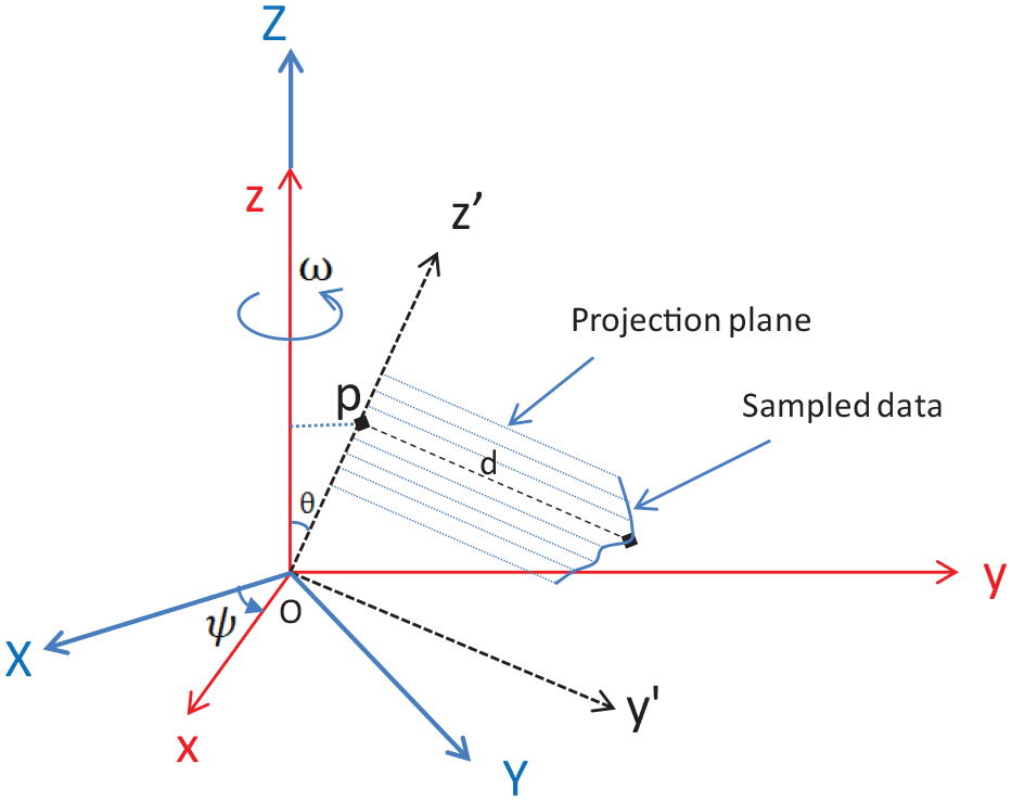
Principle of measurement system
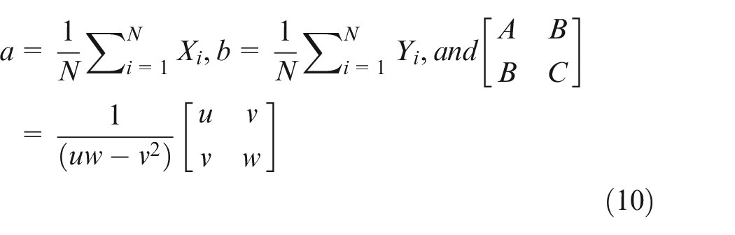
Traditionally, coaxiality measurement process is conducted in two steps. First two holes are measured by a contact measurement device, respectively. More than six points have to be measured for each hole by the contact measurement devices like coordinate measurement machine (CMM). Then the center line of the hole can be computed by two circles that are constructed from three measured points. Finally coaxiality is evaluated by the offset of the centerline away from the ideal value. The drawbacks of the approach include: (1) data captured for the two holes do not be conducted at a time so that errors will be resulted from the re-positioning and motion of the probe. (2) The acquisition of data is slow with point by point. For improving productivity, in practice, only few points are measured, which results in low in measurement accuracy.
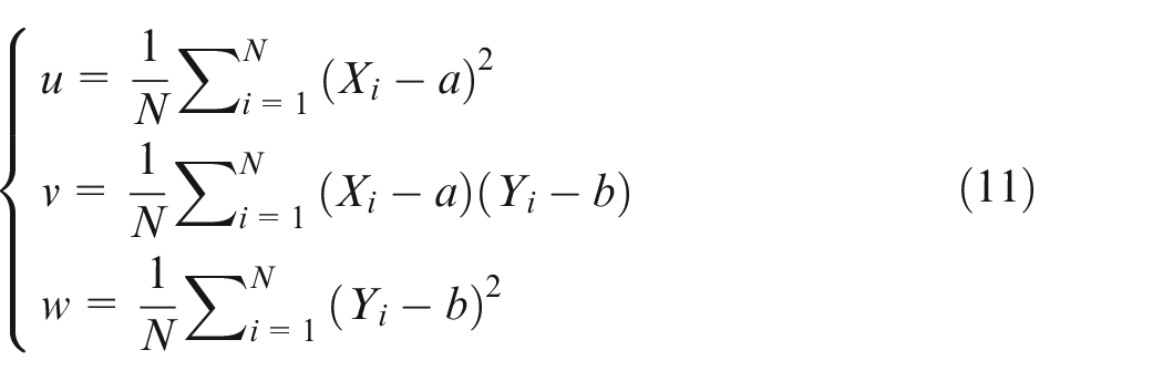
Non-contact sensors like laser-sensors are high in data acquisition speed; nonetheless the acquisition quality remains lower and depends on the surface reflection and on the measuring strategy. Few works have been conducted for non-contact sensors to be applied on dimensional inspection of part with high accuracy requirement. In product manufacturing domain, however, the requirements in terms of quality, productivity and performance have been increasing, especially for automatic production systems, where an inspection task has to be completed on-site within a few minutes. Non-contact sensors are more employed for dimensional inspection for these cases.
In this study, we proposed a new measurement system, which is used for a differential part. Different from the touch probe measurement, a laser sensor is mounted on out of holes to be measured and four holes can be measured at a time when the sensor rotates for sampling. The prototype of the measurement system is given in Figure 1.
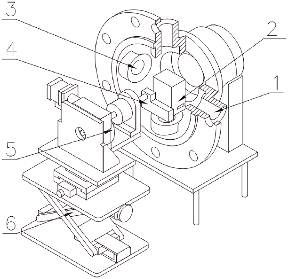
A measurement system with LJG080 laser sensor.
Where the sensor leans an angle related to the axis lines of holes so that multiply sections of the holes can be scanned for sampling during measuring. Once the 2D measurement data are obtained we can determine the centerline of hole for coaxiality evaluation.
Because the required coaxiality is 0.05 mm for this part in this study, a high-precision a 2D profile laser sensor, which is called high-accuracy 2D laser displacement sensor, is selected and used. The specification of the sensor is given in Table 1.
The specification of the sensor (Keyence LJ-G080). 23
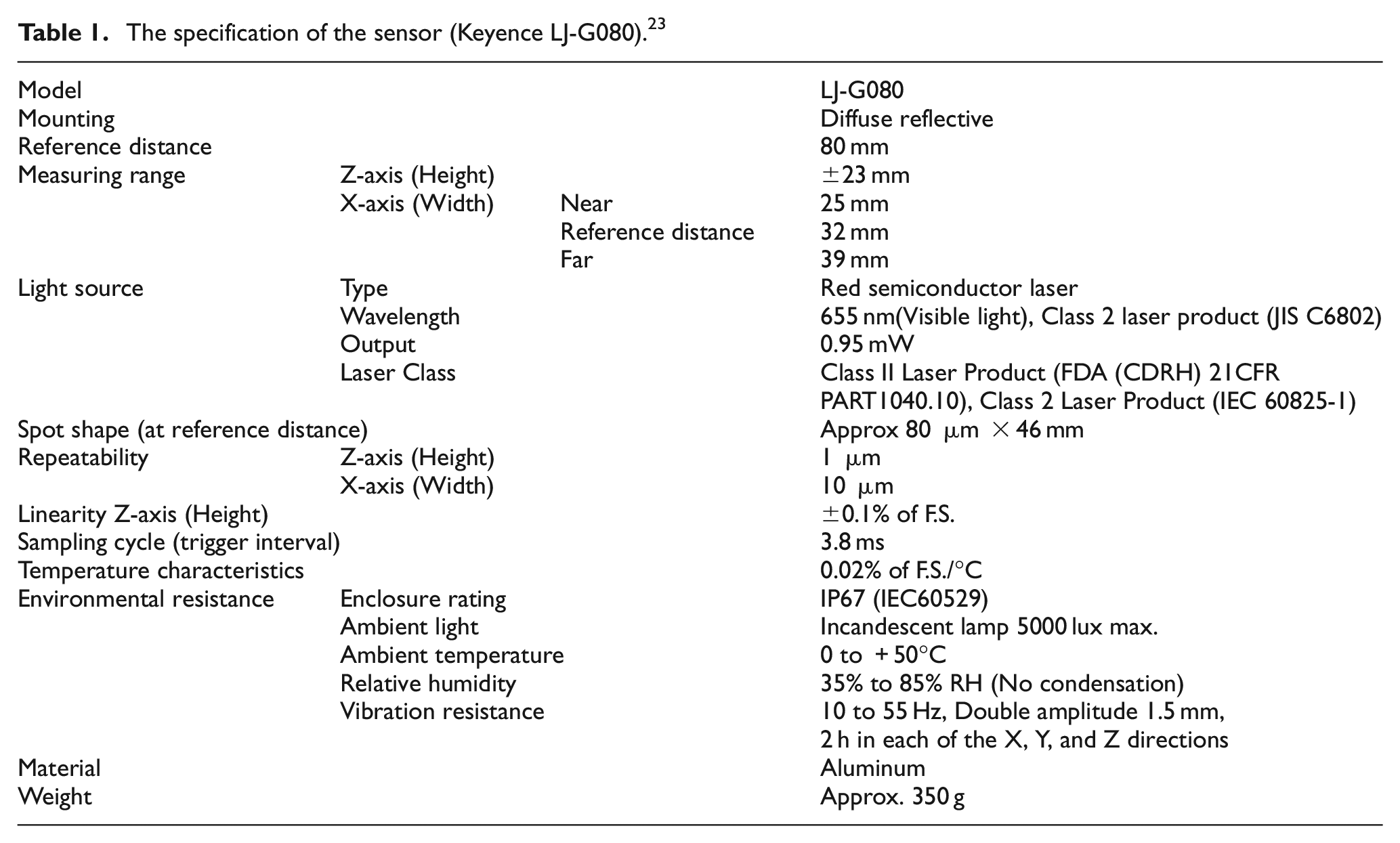
As shown in Figure 2, the laser sensor can capture about 800 points in this setup at a time with measurement accuracy 1 micrometer in depth, 10 micrometer in width. The reference distance is 80 mm for setup, the motion range
LJG080 laser sensor and its measurement: (a) is LJG080 laser sensor and (b) is the measurement principle of LJG080 laser sensor.
Data processing approach
Known from previous sections, the light axis of the laser sensor is not parallel to the normal vector of the surfaces to be measured. To improve the robust of data processing, in this study, new data processing techniques are implemented by using the characteristics of known geometries.
The data processing for holes is divided into the determination of projected section curves and the computation of centerline of hole. To determine projected section curves, the sampling data are directly fitted into ellipse profiles on a local 2D coordinate frame, which is defined on the scanning plane of the sensor. The coordinate axes are defined by the light axis and scanning profile line of the sensor, respectively. Then the parameters of the profile are transformed to 3D coordinate frame to determine the center point or profile line of the geometry. The details of the implementation algorithms will be described in following sections.
Principle of coaxiality evaluation
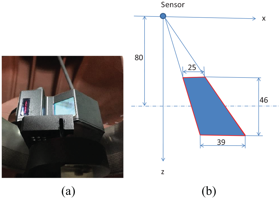
Theoretically, the measurement data of a hole, in this measurement system, are the intersection between a plane and a cylindrical surface. The parameters of the plane depend on the position and orientation of the sensor, the intersection depends on both location of the work piece and location of the sensor, as shown in Figure 3, however, the intersection must be a ellipse profile for a cylinder geometries theoretically.
Data sampling method for holes measurement.
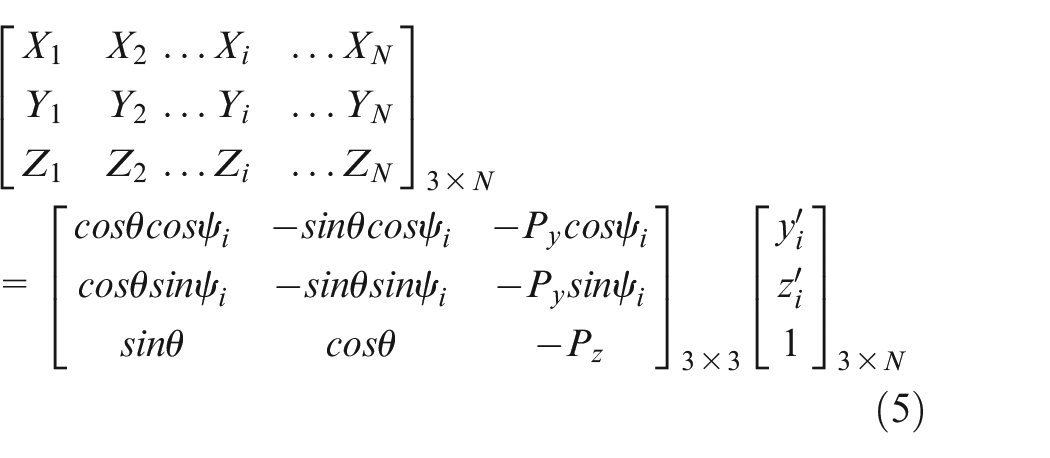
Once the measurement data are obtained the intersection or profile can be computed by using curve fitting algorithm. In this implementation, consider that the profile is an ellipse arc the measurement data will be forced to approximate as ellipse profile to improve its robust. After the parameters of the ellipse are obtained the corresponding coordinate components can be calculated. Let
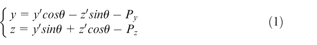
Where point (
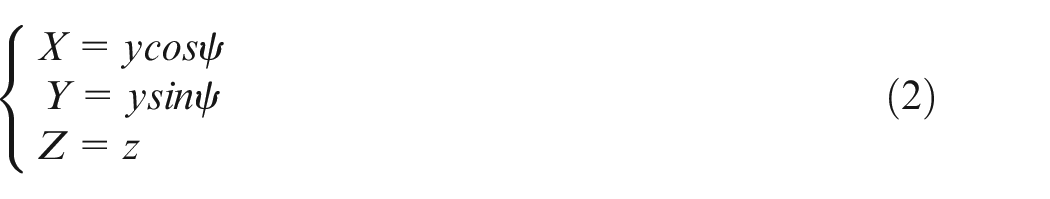
Substitute equation (1) in equation (2), it could be expressed as,
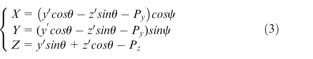
Then, three linear equations are expressed as:
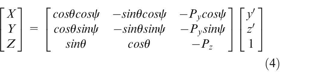
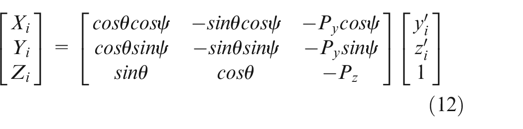
By transforming point (
Principle of holes measurement.
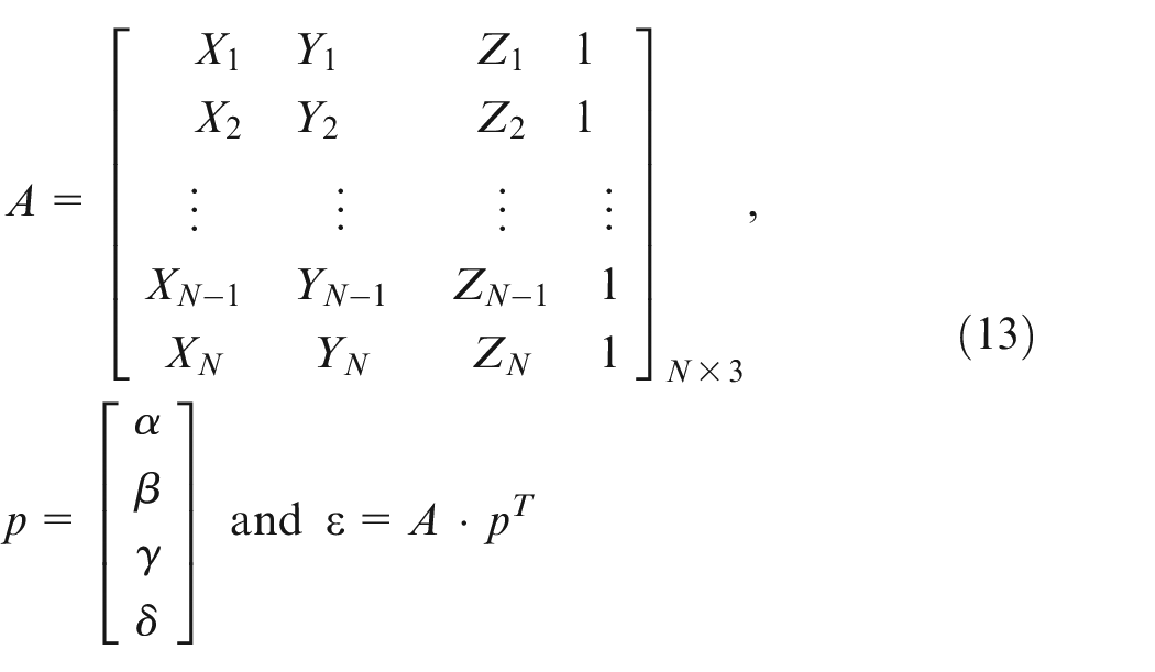
For computing centerline of a hole, two ellipse profiles are enough to determine the straight line. However, there are various errors in the measurement data in practice. Therefore, multiple ellipse profiles are computed and the least squares method is used for approximation. If
Theoretically the center obtained ellipse profiles could be used to compute offset of the profiles. Therefore, the center points can be directly used to determine the errors of cylinder surface by compute the fluctuation of the center coordinates of the ellipse profiles. By minimizing the sum of the squares of standard errors, the best straight line can be fitted from the furthest points on the ellipse profiles away from its centers. Then the centerline of the hole is computed as one of its parallel line away from a fixed distance. To validate the proposed idea, based on the ideal data, a simulation result is given in Figure 5, where the line with circle mark is the centerline of the hole.
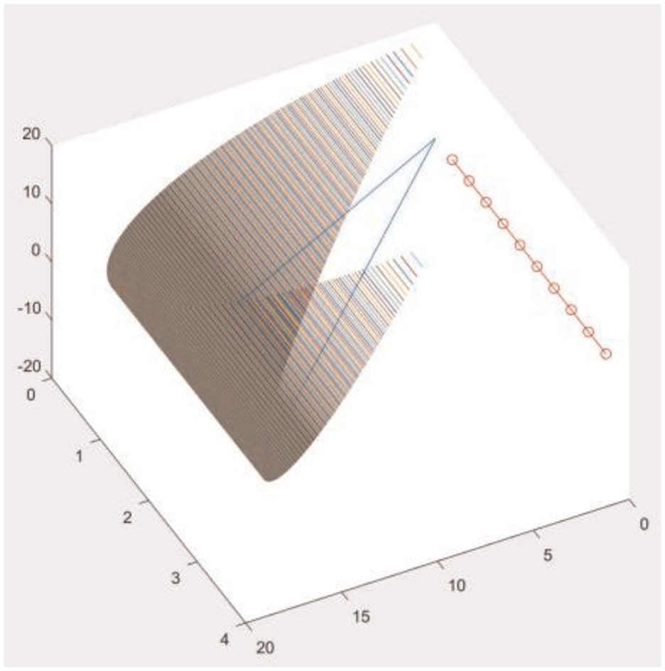
The simulation result of a hole reconstructed with ellipse profiles.
Theoretically two points are enough to determine a straight line, or the axis line of a cylinder surface could be completely determined if two ellipse profiles on the cylinder surface were known. In theory the size of the partial sampled region has little effect on the fitting precision of the axis line of hole, but there are noises on the surfaces to be measured practically and their effect can be efficiently reduced by using the least square method with multiple samples. Consequently in this application large sampled region area always is desired for high measured precision. Therefore, noting that the laser is set up on the center of the four holes for this part, as shown in Figure 1, the laser sensor should be set up with optimal slanting angle so that maximal sampled area on each individual hole can be obtained.
Improved ellipse fitting approach
Theoretically the measurement data from an ellipse section can be obtained at a time when a hole is scanned by the sensor. Due to noises, non-ellipse curve would be obtained by using traditional conic curve fitting approach. To avoid this case, in this study, an improved conic fitting algorithm is presented to force to fit the measurement data into ellipse.
As known all, conic fitting approaches have been studied in a lot of references.19–21 A general conic can be formulated by
Where
Following the idea of in reference, 21 if the conic is an ellipse it could be formulated as
To force to fit the given data into ellipse an additional constraint on the relationships among
The estimation of initial values for parameters
Where
In this application, the ranges of parameters are easily determined based on locations of the sensor and work piece. In this measurement system, since the ranges of X are determined within (9.0, 14.0), and Y within (8.5, 9.5), the initial values of
Computation of centerline of a hole
In this case, since the position and orientation of the sensor related to the work piece are changing when the rotation table rotates, the major error is from the rotary joint. With the equation (3), assuming that points (
Considering that effect of noises on measurement data, an optimum line-fitting algorithm is used for the solution. In this implementation, a least-squares formulation is first defined to determine the initial parameters of the line and then they are modified for refining.
Let the equation of the line be
Where N is the number of points,
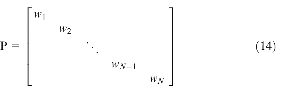
Based on the idea of the weighted least-squares method, the fitting problem is to seek a vector
Finally, a robust solution of centerline of the hole can be obtained by solving the line-fitting problem. In which the weight matrix be computed iteratively from the previous iteration to best estimate the vector
Error analysis and compensation
Error model
Practically there are two possible ways to implement the motion of joint, either the sensor or work piece. In this study, we assume that the sensor rotates around a fixed axis by a rotation table. In fact, the error model is the same for the two cases.
When the work piece is fixed the sensor is rotated around a fixed axis. Since there are clearances among components of the joint due to manufacturing errors, the motion of the joint would generate pitch error, yaw error, roll error and moving errors in three coordinate axes, as shown in Figure 6.
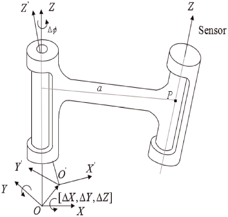
Errors resulted from the sensor rotating around Z axis.
Assume that the kinematic errors above are represented by
Where
Based on a small angle assumption,
Assume that the sensor is rotated by angle
Let

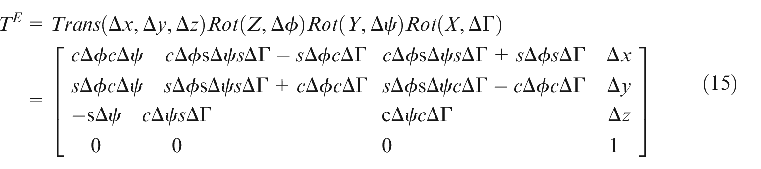
Further, the ideal transformation matrix

To describe the offset of transformation matrix

Since the error components are very small, the
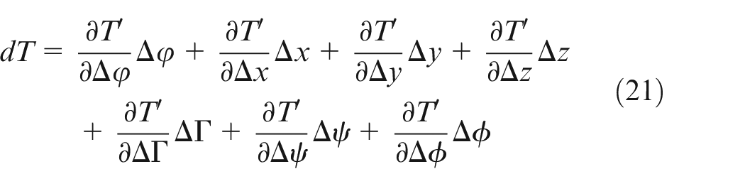
Then a differential transformation matrix

From equation (22), get
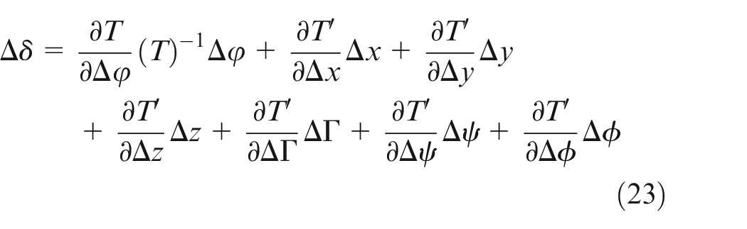
Substitute equation (17) to (23),
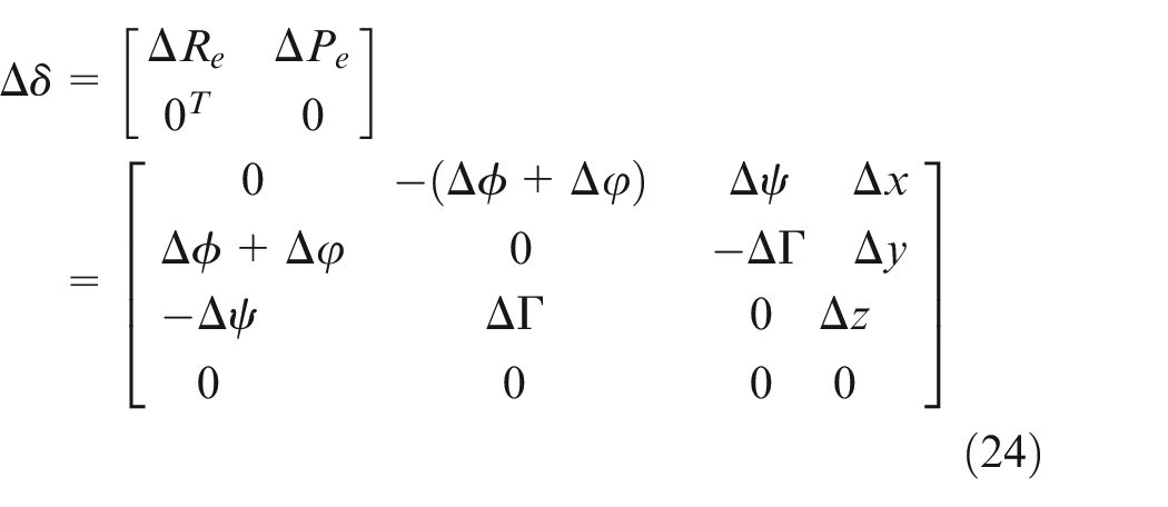
Where
Based on the error model in equation (24), the errors can be evaluated for arbitrary position and orientation of the sensor.
Error compensation
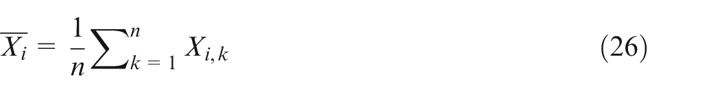
Note that the error items in equation (24) will keep constant for a long time period, which depend on the reliability of a device. If the error model is determined the error compensation can be conducted. To evaluate errors of the mechanical device for the measurement system, in this experiment, each of the points is repeat measured by varying measurement approaches many times by a laser interferometer, and then the average value and standard deviation are computed to determine its standard deviation in 3D coordinate frame.
For example, to estimate the angle error of the rotary table at some sensor’s position. The angle is measured many times by rotating the table from a datum position to the given position. Let

The average value of the position errors is formulated by
The error range of position

The covariance of the position error is calculated by
Then, the positioning uncertainty for measurements can be expressed by

With an error band with 90% data, the positioning accuracy can be calculated by

Experiments
In this experiment, a differential part is measured on this measurement device. There are four through holes with cylinder surface on the waist of the work piece and a concave spherical surface in the center of the work piece. A datum plane is on the top of the work price and another datum cylinder surface is near the bottom of the work piece. The work piece is located by the two datum surfaces for measurement, as shown in Figure 7.
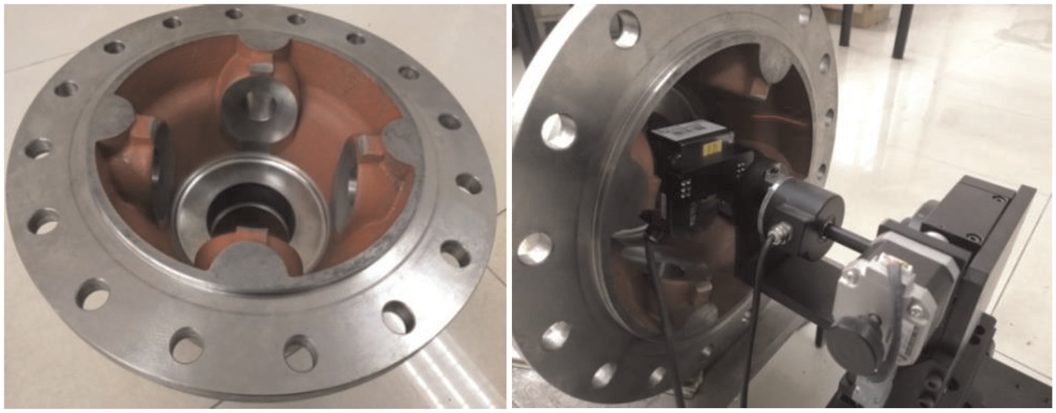
The laser measurement system and the differential part being measured.
To measure the four holes and the concave spherical surface, before the measurement starts the sensor is moved forward on the axis line of the rotation table to a given position so that the features to be measured drop into the measurement range of the sensor. Then the sensor is rotating and emitting a scan line continuously at 3.8 milliseconds to capture measurement data. Each time about 800 points are obtained by the sensor, which are the intersection of the scanning plane of the sensor and the work piece. After the sensor turns a circle the measurement is completed. Then the measurement data will be processed for evaluation purpose.
The objective of the measurement is to check the offsets of the spherical center from the centerlines of holes according to manufacturing requirement. The key dimensions and manufacturing requirements of the differential part are given in Table 2, and it can be seen that centerlines of holes and the spherical surface are very important for the quality of differential parts.
Manufacturing requirements of the differential part (mm).
Before the measurement a gauge block is used to calibrate some important parameters. Parameter
The measurement process starts when senor moves along centerline of the workpiece to stop at a given position for measuring. The measurement starts when the sensor rotates with sampling period 3.8 milliseconds. After data are obtained the measured data are segmented into eight blocks based on the locations of the holes.
Then, the measurement data of each hole and sphere surface data are processed, respectively. The centerline of each hole and the sphere center are computed.
To verify the measurement accuracy of the measurement system, a test is conducted on the spherical surface of the work piece by using alternative measurement device. For comparison, diameter 183.958 is obtained when the spherical surface is measured by CMM. In this device, the measurement data of spherical surface has been separated into eight blocks due to four holes. Only the four block data with hole-free are used for construction of the spherical surface.
For improving the reliability, the spherical surface is measured six times. The sampling data of the four regions are combined together for data process to calculate the diameter and center of the sphere. Figure 8(a) shown the center of an ellipse computed from measurement data that is sampled at a specific sensor position. In which ellipse fitting algorithm is used for solving in a 2D coordinate frame and the corresponding points in 3D coordinate frame is shown in Figure 8(b). Figure 8(c) shows the resulting spherical surface constructed from the measurement data.
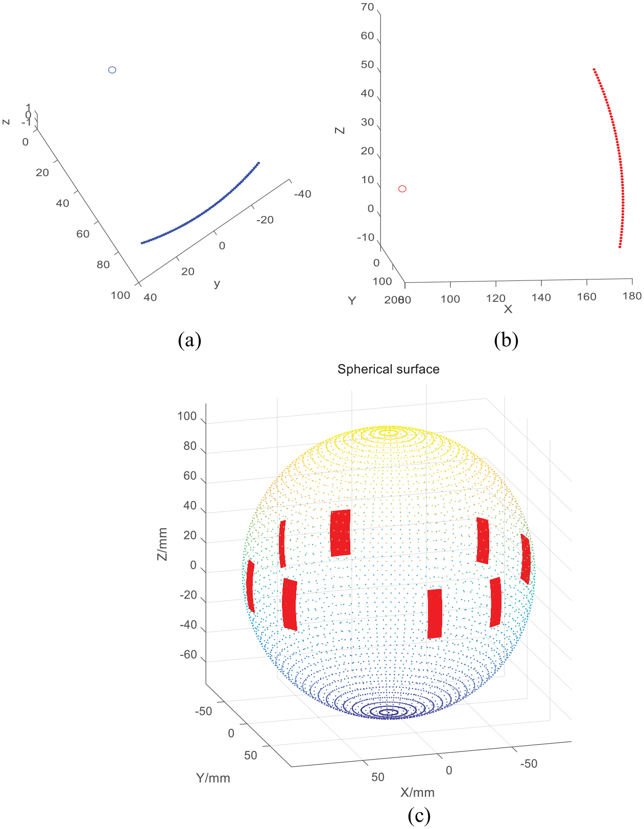
Spherical surface reconstructed from measured data: (a) shows the center of an ellipse from measurement data, (b) shows the 3D coordinate frame, and (c) shows the resulting spherical surface.
Further a comparison is conducted with the results before and after calibration, as shown in Figure 9. It can be seen that after calibration the measurement results of the part are close to the measured values by CMM.
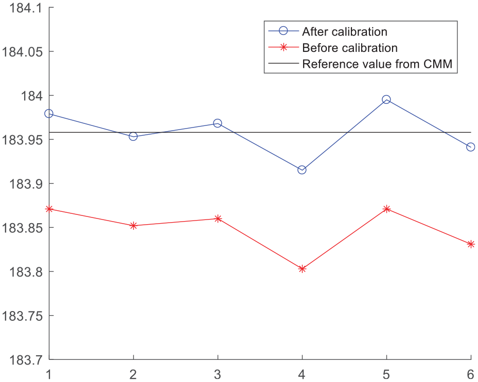
Comparison of results obtained with the parameter before and after calibrating.
In fact, hole data contained in the remained block data. Figure 10(a) shows the data points of four holes and the partial spherical surface captured by the sensor. Figure 10(b) shows the center line of a hole that is derived as the centers of ellipse profiles, and Figure 10(c) shows the resulting centerline of the hole obtained by the fitting algorithm in section 3.2.
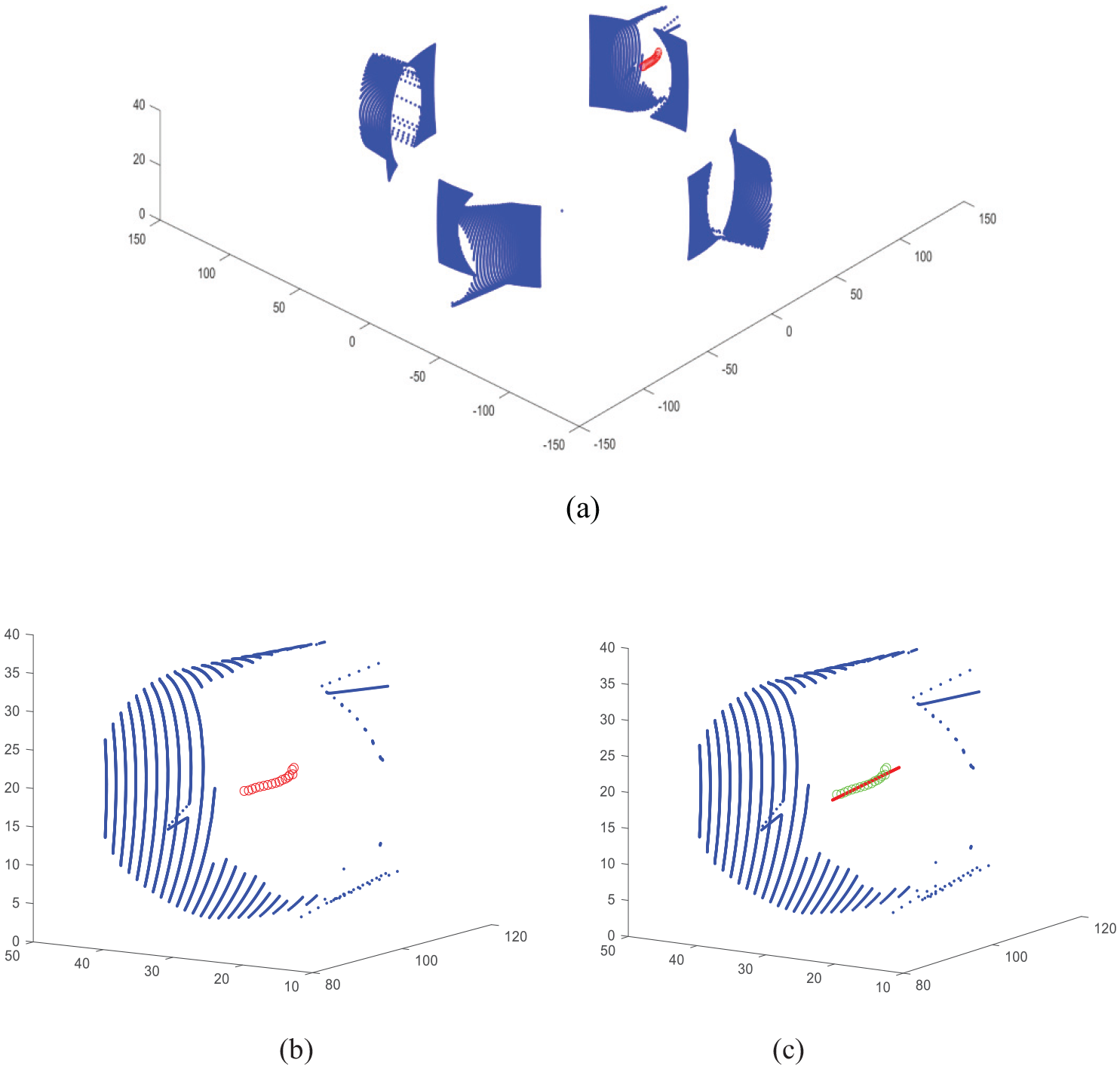
Computation of centerline of a hole: (a) sampling data of four holes, (b) the hole’s centerline represented by the centers of ellipses, and (c) the hole’s centerline after fitting.
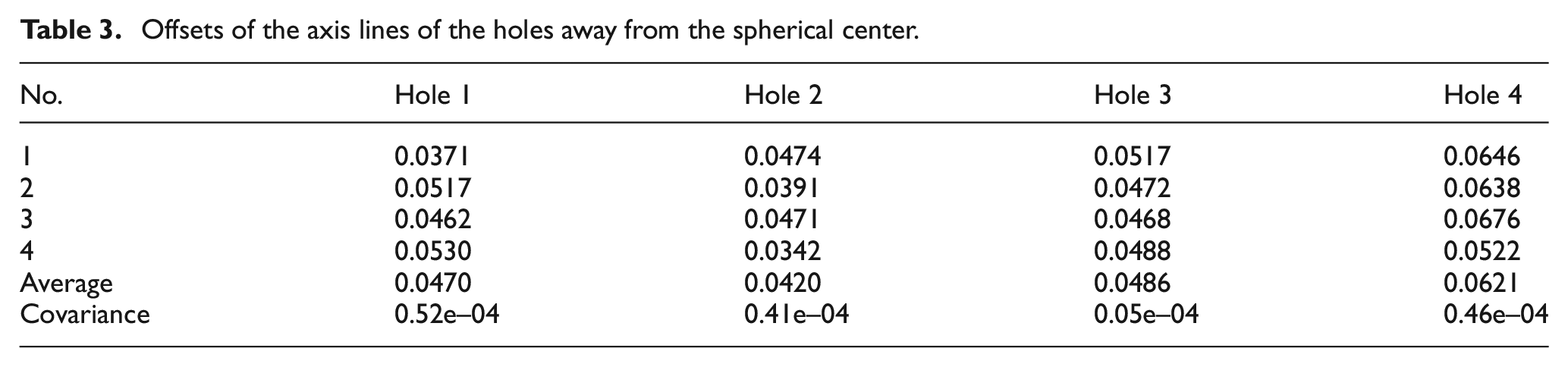
Considering that the centerlines of the holes are calculated from the constructed patch of the cylinder surface, a comparison experiment is conducted to validate the calculation results. For this purpose, the holes and the spherical surface of the work piece are respectively measured by using a CMM. First the center coordinates of the spherical surface and center line of each hole are calculated from the measured data. Then the work piece is measured by the proposed laser measurement system at one time, and their axis lines are determined. To determine the measurement accuracy the work piece is measured four times. Then offsets between the spherical center and the axis lines of individual holes are calculated based on the data sampled from the partial regions of the holes, as shown in Table 3.
Offsets of the axis lines of the holes away from the spherical center.
For comparison, the distances of the spherical center and center lines the four holes for the sampling data of the CMM are respectively calculated, as shown in Table 4.
Offsets between the spherical center and the axis lines of holes measured by the CMM.
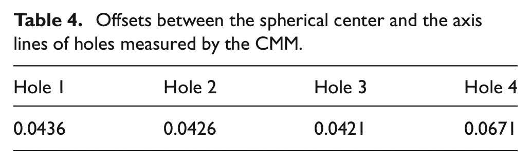
In contrast, the results obtained by the CMM are assumed as the ideal values. According to data in Tables 3 and 4, the average errors of the four holes are +0.0034, −0.0006, 0.0065, and −0.0050, and the tolerance errors are (−0.0065, 0.0094), (−0.0035, 0.0048), (0.0051, 0.0096), and (−0.0149, 0.0005), respectively. Comparing the obtained results with the manufacturing requirements in Table 2, it can be concluded that the proposed measurement device and data processing algorithms are feasible and efficient for this case. Thus, it should be pointed out that the measurement instrument focuses on the error between the common axes of the two pair holes while the dimension errors of the holes have been checked by another measurement instrument to guarantee the manufacturing quality.
Conclusion
The coaxiality measurement is important for the quality evaluation of the rotating machines. In this paper, a laser measurement principle and data processing techniques are proposed for coaxiality evaluation for a differential housing part that is machined on an automatic production line. Different from the existing approaches, the characteristics of the measurement method is that multiple features can be measured at a time. The related positions among the features are easy to be quarantined with high precision. To reduce the effect of noisy sampled data on fitting precision, an improved conic fitting algorithm is proposed to force the input data fitted to specific geometry. Although only partial surface of a feature is sampled by the measurement instrument, the surfaces of the features are continuous in geometry in this application or the parameters of the whole surface can be completely determined by the local surface. Consequently the proposed instrument and data processing algorithm did better in checking the relation positions among the features. Because the measurement is conducted at one workpiece setup high measurement precision is obtained. The validation has been demonstrated on the differential housing part by a comparison experiment. The major disadvantage is that the lengths of the holes can’t be determined by the incomplete sampled data, but the approach enables to be used for coaxiality evaluation.
Practically, on-machine measurement is required for this application due to the fact that the part is machined in an automatic production system. In this case, various factors such as the vibration of measurement instrument, the oil contamination and residual chip of the workpiece also result in measurement errors. These errors should be removed or corrected by data processing algorithm. In current study, they have not been taken into consideration, yet. Further works need to be conducted for improvement.
Footnotes
Declaration of conflicting interests
The author(s) declared no potential conflicts of interest with respect to the research, authorship, and/or publication of this article.
Funding
The author(s) disclosed receipt of the following financial support for the research, authorship, and/or publication of this article: This project is supported by National Natural Science Foundation of China (grant no. 51875445).