
Abstract
Aero-engine is an essential component of the aircraft. Due to the high cost of raw materials and precise structure, the maintenance cost of aero-engine is great. By repairing worn blades rather than replacing them with new ones, the aero-engine maintenance cost can be reduced effectively. For repairing worn blades, existing methods mainly generate tool path based on the reconstructed surface with the aid of CAM software. In this paper, an effective tool path generation method for repairing blades after additive manufacturing process is presented, which overcomes the low efficiency and complicated process weakness of existing methods. The tool path is generated directly with point clouds without surface fitting. By splitting point cloud and analyzing geometric parameters of points, machining areas could be recognized from the entire blade model. The cutter location point is generated by extending on the normal vector direction of the corresponding point. The five-axis tool path could be obtained by connecting cutter location points in turns. Tool path optimization is further studied after the generation process. These algorithms eliminate the time consumption caused by surface fitting operations, and could generate five-axis tool paths for repairing aero-engine blades efficiently.
Introduction
Aero-engine is a key component of the modern aircraft, which consists of many parts. Among these parts, the blade is one of vital constituents. The aero-engine generates the impetus by compressing or expanding the gas with the blade. Owing to the high temperature and pressure working environment, the blade is prone to wear or crack. Due to the pricey cost of raw materials and the intricate manufacturing process, the price of aero-engine blades is great. If damaged aero-engine blades are directly replaced with spare brand new ones, the cost of repairing aero-engines will rise greatly. However, if the damaged blade could be repaired and reused rather than discarded, the maintenance cost of the aero-engine could decrease significantly. Through repairing worn areas with additive manufacturing, for example metal deposition, 1 the damaged part could be reconstructed. After machining the superfluous material generated along with the reconstruction process, the worn area is repaired. The service life of damaged blades could be extended by applying the above repair method. Throughout the repair process, material reduction is more critical than additive manufacturing, which determines whether the repaired blade meets the accuracy and size requirements.
In recent decades, various blade repair methods were researched. 2 Ng et al. 3 proposed an algorithm for reconstructing the tip damage model of blades. Gao et al.4–6 proposed an adaptive repairing method based on non-contact measurement and reverse engineering, which did not depend on the digital model of the standard blade. Regarding the measurement accuracy of blade reverse engineering, Mahboubkhah et al. 7 proposed a investigation. Wang et al. 8 proposed an algorithm for reconstructing surfaces of blades based on point clouds obtained by scanning. Jones et al. 9 proposed an integrated production system for repairing blade. In the system, the tool path was established in PowerMill software.
For repairing aero-engine blades, manual operation or human intervention in the additive process is acceptable due to technological or condition limitations. However, it is not tolerable to still have manual intervention in the process of material reduction, because it will have a great impact on the processing efficiency. All of these methods mentioned above need to reconstruct surfaces with measured data, and generate tool path by the aid of CAM software. During the entire process, human intervention is inevitable. Digital surfaces of damaged blades are reconstructed by applying Bezier or B-spline surface fitting algorithm on measured data, and then machining trajectories are generated based on these surfaces. The fitting operation not only causes a large computation effort, but also makes the repairing process complicated and inefficient. Furthermore, it is essential to avoid distortion on the geometrical shape of the original part during the process of fitting the measurement data into surfaces approximately. As can be seen from the above reasons, existing methods are not efficient on generating the tool path for repairing damaged blades.
In the field of advanced machining, the technology of constructing machining trajectories directly with measured data has been gradually developed in recent years. For these methods, machining trajectories could be generated with point cloud directly,10–12 including three-axis13–15 and five-axis12,16,17 tool path. The improvement could eliminate the surface fitting operation on measured data, as well as the requirement of using CAM software for creating machining trajectories. The technology has been applied on machining complex surfaces 18 and generating tool path for rough milling cutters. 19 However, in the field of damaged blades repair, the geometric information of damaged surfaces has changed due to the additive processing on aero-engine blades. Point clouds of damaged blades could not represent geometric information of nominal blades. If above technology is applied directly on point clouds of damaged blades, the generated tool path could not satisfy repairing requirements. In addition, all these methodological researches focus on machining rather than repairing. These two modes have significant difference. For machining new parts, it is necessary to generate tool path for entire surfaces. However, only the tool path corresponding to worn areas is required to be generated for repairing damaged parts. Therefore, although these methods could directly generate tool path with point cloud model, they could not be directly applied on damaged blades repair.
In order to overcome these low efficiency and complicated process of existing methods, this paper submits a new method, which can generate tool path directly with point clouds for repairing aero-engine blades. The core purpose is enhancing the efficiency of generating tool path by simplifying the whole process. The method comprises several significant advantages. (1) The measured data is not required to be fitted into surfaces, which reduces the time consumed by processing data; (2) Region growing algorithm 20 and clustering algorithm are applied to obtain the point cloud corresponding to target regions; (3) Based on point clouds of nominal blades and damaged blades, geometric parameters of points can be directly solved, including normal vectors and machining depth; (4) According to above spatial geometric information, areas to be machined can be automatically identified and located without the requirement of manual intervention; and (5) Tool path for repairing blades could be directly generated from point cloud with high efficiency. Compared with existing methods, the new method simplifies the whole process of tool path generation.
In this paper, some high-pressure turbine blades are regarded as examples, which have been processed by additive manufacturing technology. These examples can be used to test the proposed algorithm. Tool path can be generated directly with point cloud by the aid of these algorithms. The result of experiments shows that the method can generate machining trajectories efficiently compared with traditional methods.
Detection of worn areas on blades
In order to generate the tool path, it is imperative to obtain geometric information about repairing areas. Therefore, it is necessary to convert aero-engine blades into point clouds. Worn areas are mainly concentrated in the blade body and tip regions, which are main work areas. Hence, it is necessary to identify these parts among the whole point cloud. Through applying k-means cluster algorithm, blade body region could be acquired. However, the position of the worn area on the blade body region is indeterminate. For locating the target area, a lot of geometric information is required, which includes normal vectors of the point cloud belonging to worn areas and spatial distances from the point cloud to surfaces of nominal blades. The specific worn areas could be recognized and located by analyzing these data.
Blade body part recognition
In the measurement process, the articulated arm scanner is applied for scanning blade surfaces, which is a kind of non-contact measurement device. The measuring accuracy can reach 30µm, and the measuring range is less than 1.8 m. There are two types of models acquired, including point clouds of damaged blades and nominal blades. To facilitate the calculation of differences between point cloud models, two kinds of models are required to be matched. Model matching operations are carried out in the Geomagic Studio software environment. Through matching operation, baselines of models can be aligned. The example of point clouds corresponding to blades is shown in Figure 1(a), which includes more than one hundred thousand points. All of above models are exported in OBJ format.
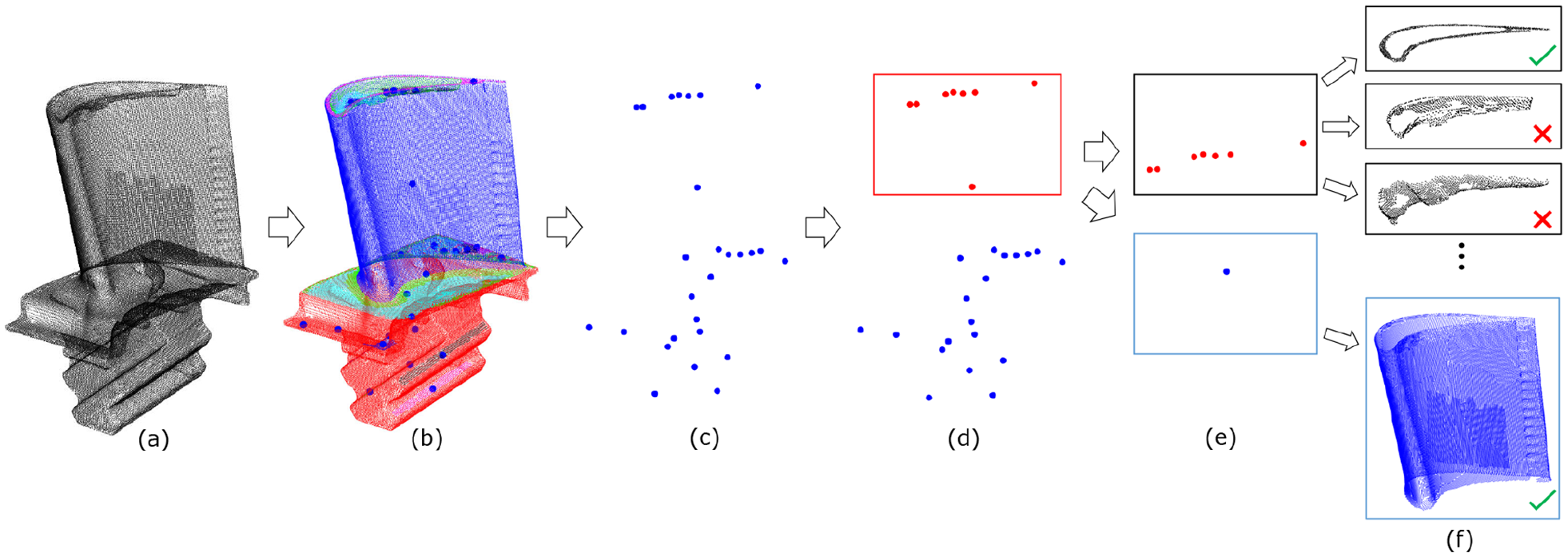
Target area recognition process based on K-means cluster algorithm: (a) is an example of blade point cloud, (b) shows regions of the point cloud, (c) represents center points of regions, (d and e) show results of the first and second clustering, and (f) represents the results of identification.
The structure of aero-engine blade model is complicated, which consists of many planes and surfaces. Therefore, it is difficult to directly obtain target areas. To acquire models of blade surface and tip area, it is inevitable to separate the entire model into regions. For separating point cloud, it is suitable to implement the region growing algorithm. Region growing rules are determined by the angle between the normal vector of the seed point and adjacent points, as well as the angle between the normal vectors of adjacent points and spatial coordinate direction. Normal vectors of points in the point cloud can be calculated by traversing the nearest neighbor points. 21 According to region growing rules, it can determine whether two adjacent points belong to the same category. Whenever a new region is generated, it will be assigned with a corresponding geometric feature type, including plane, surface and uncertain type. After the whole point cloud has been traversed, it could be decomposed into multiple regions, as shown in Figure 1(b).
By calculating coordinate values of points, the center point of each region can be obtained. These points could be used to represent different regions, which are shown in Figure 1(c). As long as the corresponding central point is located, the target area can be recognized. The overall structure of aero-engine blades is distinguishable. The structure of the blade body is relatively simple. However, the structure of blade root is complex, which consists of many stages. Although the entire point cloud is decomposed into multiple regions, the distribution of these regions still conforms to this feature. Therefore, the distribution of above central points has certain regularity. By applying k-means clustering algorithm on these points, it is realizable to identify target central points.
According to the structural feature of aero-engine blades, it could be deduced that the structure of the blade root is more complicated, and the construction of the blade body is simple. Therefore, the number of regions belonging to blade root is larger than the number corresponding to blade body. The target subclass can be identified through distinguishing the number of central points between two subclasses generated by k-means clustering algorithm, as shown in Figure 1(d). Central points in the target subclass represent regions belonging to blade body model. On the basis of the initial clustering result, the k-means clustering algorithm is applied again to realize the subdivision of the blade body model. The result of subdivision is shown in Figure 1(e). During the segmentation process, each region is assigned with a definite geometrical type. Target regions can be finally obtained by identifying geometrical categories, as shown in Figure 1(f).
Normal vectors calculation for analyzing worn area
For repairing damaged blades, it is necessary to locate areas that are required to be repaired. To realize this requirement, there are many parameters needed to be acquired, including normal vectors of points and spatial distance from points of damaged blades to surfaces of nominal blades. In order to calculate these parameters, points of the blade body region corresponding to nominal blades are required, as shown in Figure 2(a).
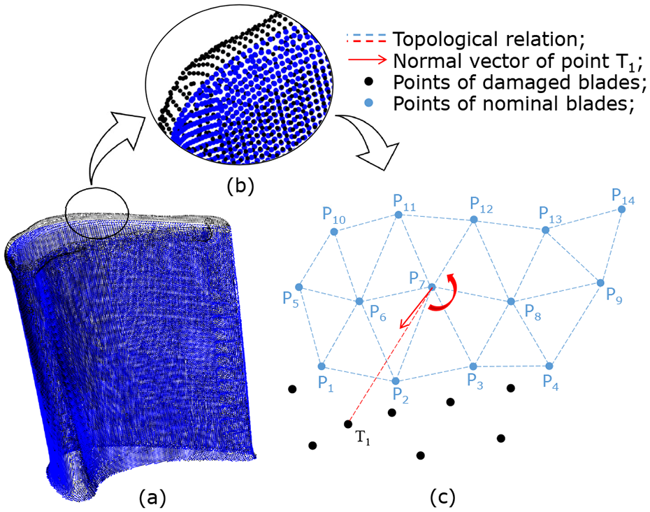
The calculation principle of normal vectors: (a) represents point clouds of nominal blades and damaged blades, (b) is a partial enlarged view, and (c) shows the process of calculating normal vectors.
The specific process of normal vectors and spatial distance calculation is shown in Figure 2(c). For the point
Identification of damaging areas on blades
After damaged blades are processed by additive manufacturing, the specific spatial position of damaging areas cannot be determined in advance. In order to detect the position of damaging regions, the entire blade body region is divided into many interlayers by a series of flat planes, as shown in Figure 3. These planes are parallel to the X–Y plane, and the distance between adjacent flat planes is 1 mm. By applying the algorithm proposed above, spatial geometric parameters of points in each interlayer could be obtained. Based on these data, the average value of spatial minimum distances corresponding to each interlayer is calculated.
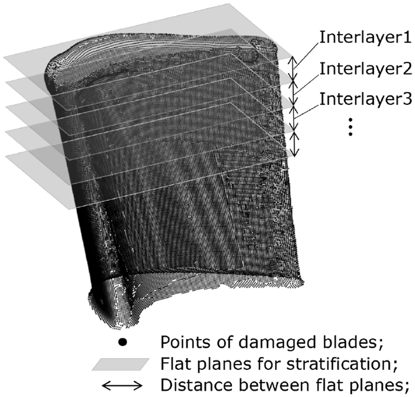
Partition of point cloud models.
In general, there are two typical kinds of areas that are required to be repaired, as shown in Figure 5(a) and (b). The former is required to repair the entire tip area, and the latter only needs to repair the local area at the top of blade. After these two models are processed by the above algorithm, average values of spatial minimum distances are acquired. The distribution of these average values is shown in Figure 4. There are two curves of the average distance in the figure, corresponding to two typical types of damaged blades. For the entire tip repair, the average distance initially drops sharply from the maximum value and then tends to be gentle. For the local repair, there is basically no change during the initial stage. In the middle area, the average distance starts to rise first and then fall. The judging threshold is the average value of the spatial distance corresponding to all the interlayers. Since the distance is larger than zero, the range of the threshold is also larger than zero. For points in an interlayer, if the corresponding average distance is larger than or equal to the judging threshold, this interlayer needs to be machined. Through discriminating these interlayers, the spatial distribution of damaging areas could be acquired in the Z-axis direction.
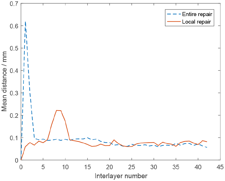
Mean distance distribution diagram.
Based on the spatial distribution above, the boundary of damaging areas in the Z-axis direction can be derived. However, this is not sufficient. The damaging area may be the entire blade tip or just a portion. Since the spatial distance of points in damaging areas is larger than that in the area that is not required to be machined. By setting these spatial distances as judging condition, it is possible to identify and locate damaging areas. In view of this, region growing algorithm is used in accurately locating process. According to the distribution of damaging areas in the Z-axis direction, the number of interlayers corresponding to damaging areas is obtained. These numbers include i, j, k, and m and so on, as shown in Figure 5(c) and (d). After processed by the region growing algorithm, the point cloud corresponding to damaging areas could be detected. These points are the basis of generating tool path.
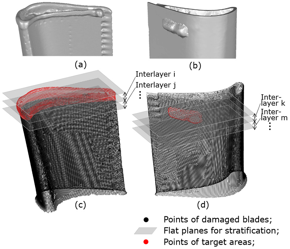
Two kinds of typical maintenance areas: (a) represents entire repair, (b) shows local repair, and (c and d) shows detection areas.
Blade repairing path generation and optimization
In the domain of aero-engine blades repair, existing methods generate tool path with the assistance of CAM software. If the tool path could be generated directly with point cloud, no additional assistance and manual intervention is required. Through applying algorithms above, the target point cloud corresponding to damaging areas is acquired. Based on the model, as well as corresponding spatial geometric parameters, cutter contact (CC) points, and cutter location (CL) points can be calculated. The tool path could be generated through connecting CL points. After the generation process, tool path detection and optimization is also study in following chapters.
Tool normal calculation based on points
After damaged blade are processed by additive manufacturing, there will be a significant change on geometric parameters of blade surfaces. This causes bad distribution quality of points among point cloud model, as shown in Figure 6(a). Therefore, it is necessary to adjust the arrangement of points. Based on cross-section algorithm, the process of generating intersection points is shown in Figure 6(c). The parallelogram with solid line represents cross-section, and solid points
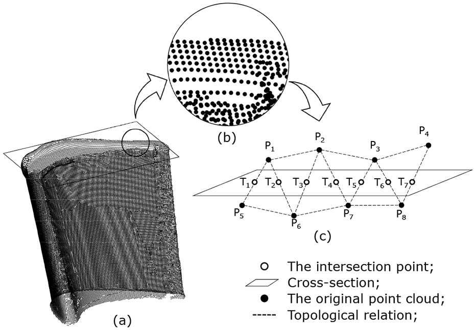
Optimization of the point cloud: (a) shows uneven distribution of points, (b) is a partial enlarged view, and (c) represents the process of generating intersection points based on cross-section method.
After point clouds of both nominal blades and damaging areas are processed by the cross-section method, corresponding intersection points are generated. In order to generate five-axis tool path directly with these intersection points, it is obliged to calculate cutter axis(CA) vectors. Therefore, it is necessary to calculate normal vectors of points, which are the basis of calculating tool axial vectors. However, surfaces of damaging area have changed significantly, after the area is processed by additive manufacturing. Normal vectors of these surfaces can not represent the normal vector of original standard surfaces. Hence, these existing data can not be directly employed to solve CA vectors. In view of this, normal vectors corresponding to original standard surfaces are solved by calculating the minimum distance from the point of damaged blades to the surface of nominal blades. The whole calculating process is on the basis of the cross-section method, as shown in Figure 7.
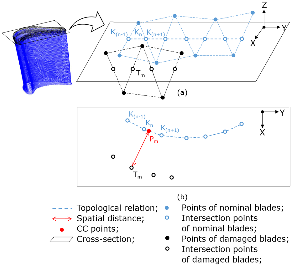
Apply cross-section method on point clouds of both nominal blades and damaged areas: (a) represents sorting process of intersection points and (b) shows minimum spatial distance and normal vectors of point Tm.
A lot of new intersection points are generated by intersecting the point cloud with a flat plane. The flat plane represents tool path plane. Many line segments are generated by sorting these points and connecting them in turns, as shown in Figure 7(a). Geometrical parameters of points belonging to damaged areas could be calculated based on these line segments. For points of damaged areas, it is feasible to obtain normal vectors and spatial distances through solving the nearest neighborhood point on these line segments.
For the point
Generating tool path with CL points
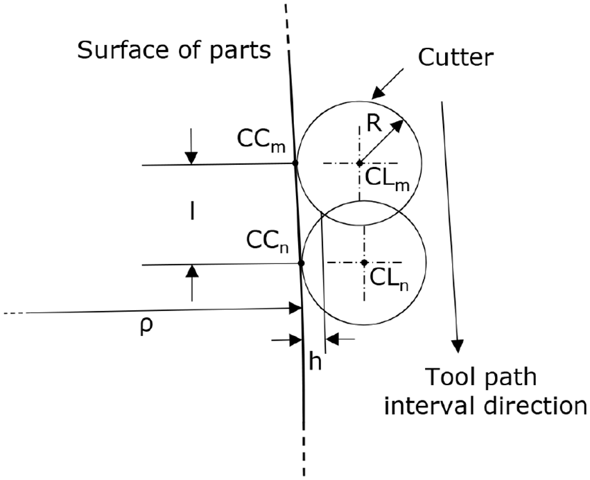
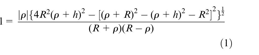
The entire tool path for repairing damaged blades contains many layers. The minimum spatial distance between two adjacent layers is called interval. The interval corresponding to the tool path is determined by various parameters. These parameters are related to tools and machining surfaces, as shown in Figure 8. The parameter l represents the interval of machining trajectories. The parameter h represents the scallop height, and the parameter R is on behalf of the tool radius. In addition, the parameter
The interval between different layers of tool path.
Because different types of aero-engine blades have separate specific geometric parameters. These parameters have a critical impact on calculating the interval of tool paths. To generate tool path for different types of aero-engine blades, the interval should be set as a tunable parameter. In addition, the effect of diverse tool radius could not be overlooked. Therefore, it is necessary to acquire the corresponding interval based on definite types of blades and machining parameters.
Through adjusting the cross-section based on the interval calculated with the equation (1), 22 there are a series of flat planes created, as shown in Figure 9(a). Base on these flat planes, a large amount of intersection points are generated through applying the cross-section method. It is possible to achieve spatial distances and normal vectors corresponding to these points. CL points could be generated by extending the length of the tool radius in the direction of the normal vector, as shown by red points in Figure 9(b).
In order to meet technological requirements for repairing damaged aero-engine blades, it is necessary to process worn areas with the five-axis machining manner. Therefore, during the process of tool path generation, it is necessary to synchronously calculate CA vectors corresponding to CL points. After the whole point cloud of the nominal blade is segmented into regions, the model of the blade tip plane can be obtained. Based on the model, the normal vector of the plane is calculated. For the CL point, the corresponding CA vector can be obtained by solving the combined vector of its normal vector and the normal vector of the tip flat plane above. These CA vectors could provide information about tool posture.
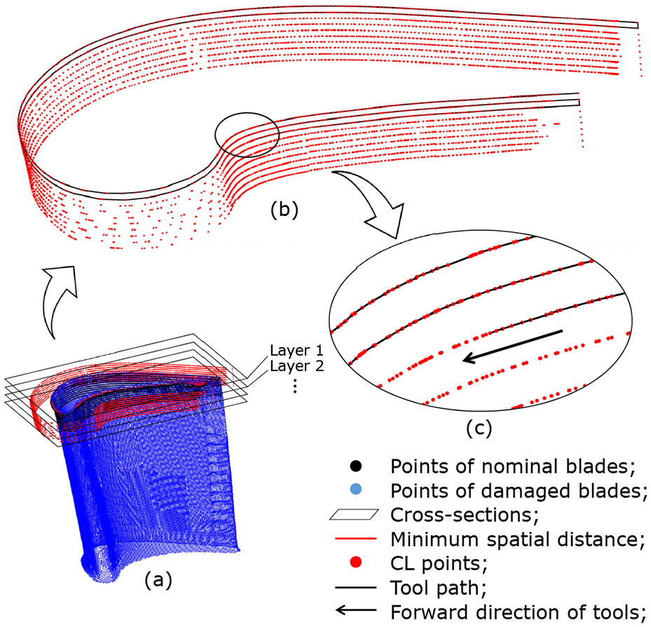
The process of generating the tool path with CL points: (a) shows CL points generation based on cross-section method, (b) represents all CL points for generating the tool path, and (c) shows the generation process of tool path.
After being processed by the cross-section method, the point cloud of the damaged area is converted into layers of points. Based on these points, CL points are calculated in turns. Therefore, CL points are also divided into many layers. To generate tool path, the sorting algorithm is applied to CL points. The specific sorting procedure is as follows. For all CL points on the same layer, the beginning point of tool path is selected by filtering out coordinate position and normal vectors. At the same time, the starting direction of tool path is determined based on the actual machining requirement. After the beginning CL point is selected, neighborhood points corresponding to the point are traversed, and vectors from the beginning point to neighborhood points are calculated. For a neighborhood point, if its vector is consistent with the starting direction of tool path, this neighborhood point is identified as the next CL point. Eligible neighborhood points will be set as next new starting point. Through applying iterative calculating process, all CL points on the same layer are sorted. The tool path corresponding to one layer could be generated by connecting CL points in turns. It is critical that whether the choice of the starting point for the tool path is accurate throughout the sorting process. If the starting point is selected incorrectly, it may cause serious error. The tool path could be generated by sorting all CL points by layers and connecting them in turns, as shown in Figure 9(c).
Abnormal trajectories recognition and optimization
Base on above algorithms, machining trajectories can be directly generated with the point cloud. However, there are a few abnormal line segments on the tool path. The specific reason for this phenomenon is shown in Figure 10. The point cloud consists of a large amount of points. Although the point cloud is optimized by the cross-section method, there are some points that are non-uniform. Due to these uneven points, there are some errors during calculating normal vectors corresponding to the point cloud. In the procedure of generating CL points, these errors are amplified by the extension in the direction of the normal vector. Therefore, some abnormal trajectories are created along with constructing the tool path with CL points.
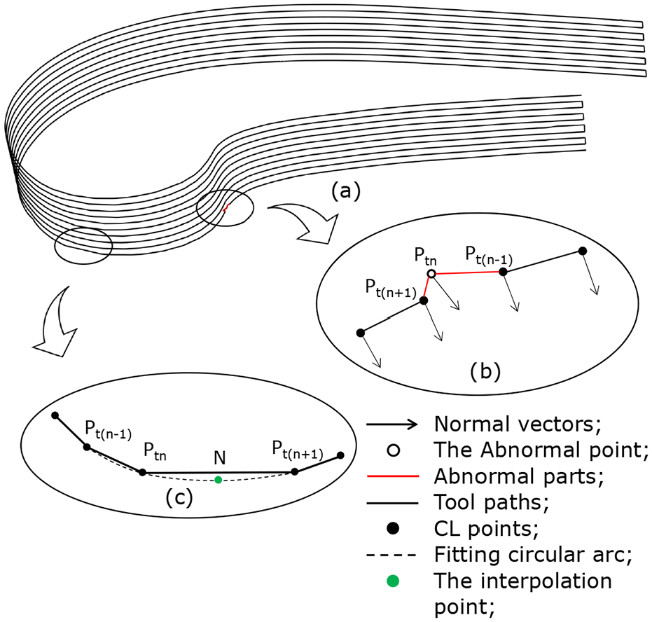
Tool path optimization method: (a) represents the tool path constructed with point cloud, (b) shows abnormal regions on the tool path, and (c) represents the application of the circular arc interpolation on overcutting machining trajectories.
These abnormal trajectories will affect the quality of tool path. Therefore, it is necessary to identify and optimize anomalous parts of tool path. By analyzing the spatial geometric relationship of trajectories corresponding to these abnormal regions, it can be concluded that the angle between the forward direction of cutter and normal vectors of CL points is abnormal. In routine circumstances, the forward path of cutter is perpendicular to the normal vectors of CL points, and the angle between these two directions is approximately larger than 60° and less than 120°. By calculating the angle between the normal vectors of CL points and the forward direction of cutter, abnormal trajectories can be identified. The algorithm principle is shown in Figure 10(b). For a CL point
Since the tool path is generated directly with point cloud without fitting operation, it is composed of line segments. However, the length of some machining trajectories may be longer or shorter. This phenomenon is due to the uneven distribution of points in the point cloud. Too long machining trajectories may cause overcutting during the actual manufacturing process, especially in the areas where the curvature is large. The problem can result in an increase in machining errors. Therefore, it is necessary to perform interpolation on excessively long machining trajectories for regions with large curvature.
There are many interpolation algorithms23,24 in machining trajectories planning. In order to maximize the efficiency of generating tool path while ensuring the machining accuracy, the circular arc interpolation algorithm is used for optimizing overcutting machining trajectories. The specific steps are as follows. By selecting two points at both ends of the target line segment, as well as one point adjacent to this segment, these three points could form a circular arc. According to the average length of machining trajectories, interpolating points are evenly selected on the this circular arc, as shown in Figure 10(c). The average length is larger than 0.1 mm, which is related to the distance between points in the point cloud. By using the interpolation algorithm, overcutting phenomenon can be clearly eliminated.
Case study and experiment
To generate five-axis tool path, all proposed algorithms have been implemented and coded in C++. Two demo aero-engine blades are validated by these algorithms, which run on a PC with a 3.4 GHz Intel Core CPU and an AMD Radeon HD 7400 Series graphics card. The blade used for testing belongs to high pressure turbine components. Since the blade works under high pressure and high temperature conditions, it is prone to generate abrasion on the blade surface. Furthermore, in order to ventilate and refrigerate, the structure of blades is complex. Therefore, it is illustrative to test the proposed algorithm with this kind of blade. The validity of the algorithm can be verified through the test. After the point cloud model is processed by these algorithms, machining trajectories corresponding to two demo blades are directly generated with point clouds, as shown in Figure 11. The tool path is displayed in the CIMCO Edit 8 software.
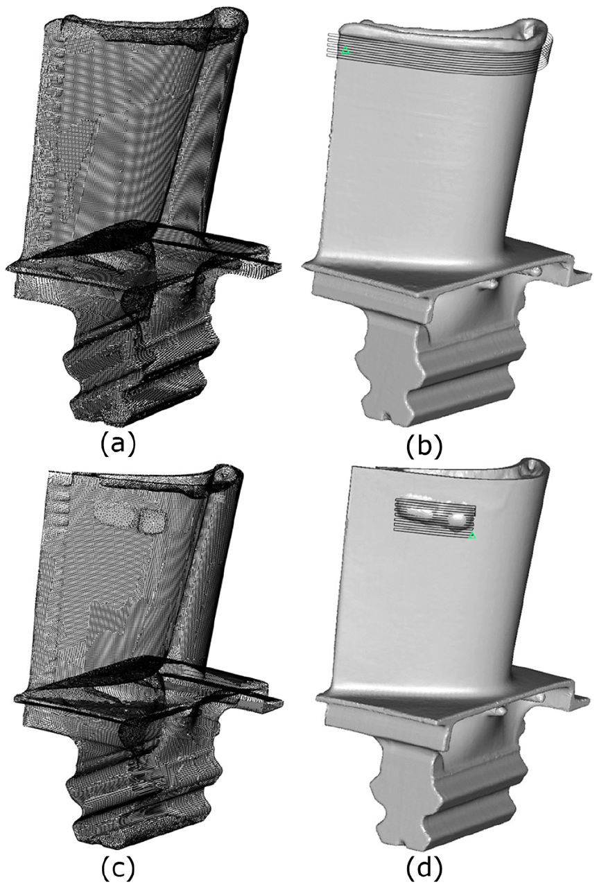
Two point clouds of damaged blades and two tool paths corresponding to them: (a and c) represent demo 1 and demo 2 and (b and d) represent tool paths generated for demo 1 and demo 2.
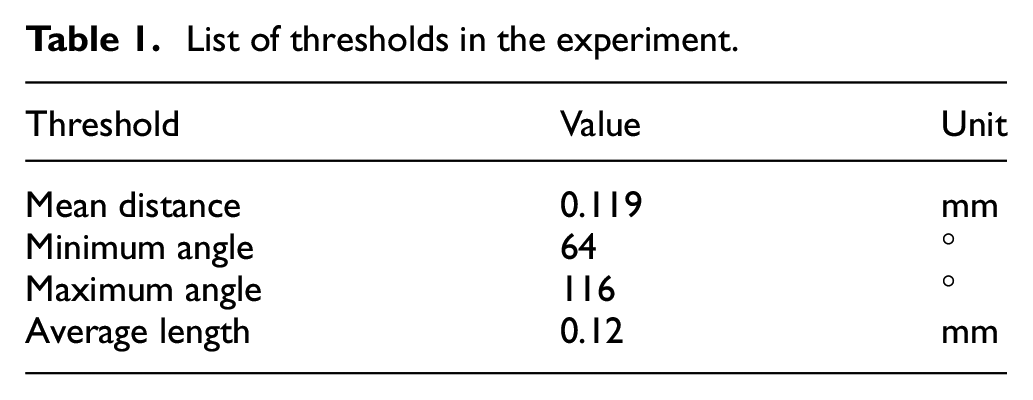
The method proposed in this paper can generate the machining trajectory for the entire tip repair, as well as the tool path for regional surface repair. The repair process of the damaged blade is shown in Figure 12, which is running in the simulation environment. The radius of tool is 5 mm, which is depended on the curvature radius of parts. All values of threshold in the experiment is listed in Table 1. No CAD or CAM software is required in the process of tool path generation. The calculation of the machining trajectory does not require manual intervention.
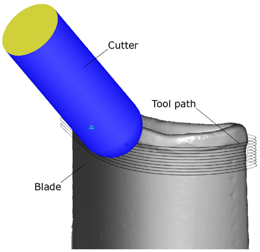
The schematic diagram of machining blades.
List of thresholds in the experiment.
The specific machining method of the aero-engine blade can be determined according to the process requirement. Conventional five-axis machine tools and robotic machining systems are optional. There are no restrictions on the choice of processing methods. Of course, the accuracy of disparate processing methods will be different. Through proper post-processing, the tool path generated by the algorithm is suitable for ordinary five-axis machining systems.
The accuracy of tool path is mainly affected with the point cloud, since the machining trajectory is directly generated with points. The precision of point cloud depends on measurement equipment. Furthermore, the number of samples in the measurement process also affects the accuracy of tool path, since there is a loss of information. The higher the density of points, the less information is lost in the collection process. If the information of the point cloud is sufficiently rich, interpolation is not necessary. The accuracy of the tool path can be improved by reducing the interpolation operation. Of course, it is important to balance the relationship between measuring efficiency and the number of samples.
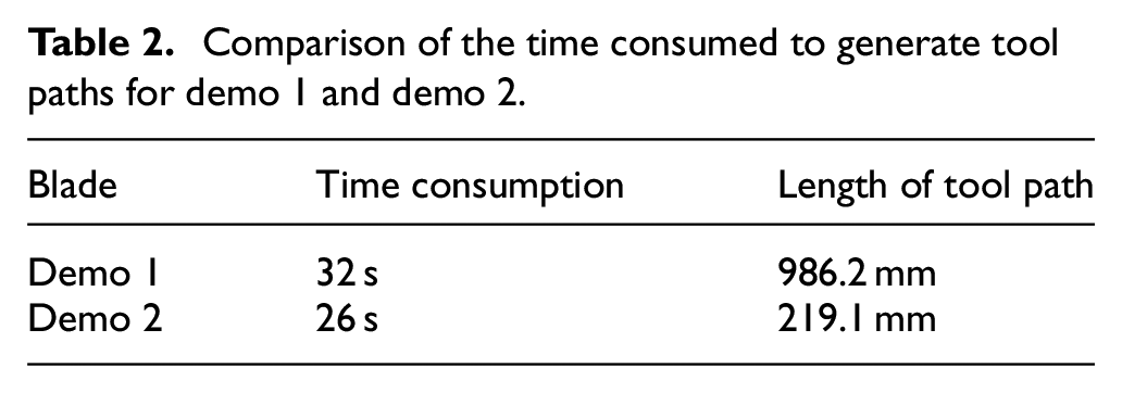
The time consumed by generating tool path with the point cloud is shown in Table 2. It can be concluded from the data that the algorithm proposed in this paper can quickly generate machining trajectories directly with point cloud in a short time. For the same kind of blades, the time consumed by the algorithm is related to the length of tool path. Generally speaking, the interval height of the machining path, the feed amount of the cutter and other parameters has an influence on the length of tool path. In addition, the impact of point cloud data on the running time of the algorithm cannot be ignored.
Comparison of the time consumed to generate tool paths for demo 1 and demo 2.
Conclusion
Through applying algorithms proposed in above chapters, the five-axis tool path used for repairing damaged blades could be generated with point cloud directly. This method improves the efficiency of tool path generation. The damaged areas recognition algorithm enhances the applicability of the tool path generation method.
Compared with existing methods, the proposed method has many advantages. For the new method, the tool path can be generated directly from the measured data through algorithm processing, and the whole process is simplified. There is no surface fitting operation needed in the method, as well as CAM softwares. These factors determine that the new proposed method is more efficient than existing ones. Furthermore, the proposed method has the potential to generate trajectories online.
However, the entire tool path consists of line segments. After the blade is machined, the surface quality of blades may not meet the requirements. Therefore, it is required to polish machining areas of blades. To alleviate this effect, the fitting algorithm for machining trajectories generated with point cloud can be explored to enhance the surface quality after machining. In the process of CL points generation, the effect of intersection between different normal vectors is not considered in this paper due to the short extension length. This problem may be solved by optimizing the CL points sort algorithm.
The advantage of this paper is the ability to directly generate the tool path for repairing damaged blades with the point cloud. On this basis, more research work can be carried out in the future. It is possible to develop a tool path generation system for repairing aero-engine blades. Based on this system, it is valuable to generate tool paths for restoring different types of damaged blades. This is especially beneficial for repairing large quantity of damaged aero-engine blades rapidly.
Footnotes
Declaration of conflicting interests
The author(s) declared no potential conflicts of interest with respect to the research, authorship, and/or publication of this article.
Funding
The author(s) disclosed receipt of the following financial support for the research, authorship, and/or publication of this article: This research was supported by the National Science and Technology Major Project(2017-VII-0010-0104).