
Abstract
The concept of additive–subtractive hybrid manufacturing provides a new idea for the manufacturing of high-precision complex structural parts. Currently, under the five-axis additive–subtractive hybrid manufacturing mode, existing research work concerned with sequence planning issues have limitations. This article presents a sequence planning method for hybrid manufacturing of complex structural parts with high precision. The initial printing direction of parts was determined based on an iterative search method and the initial hybrid manufacturing sequence was constructed by part volume decomposition, which solved the coupling problem of printing direction decision and machinability calculation. Under the constraint of tool accessibility, the whole planning of the hybrid manufacturing sequence was realized based on greedy algorithm. This method has achieved highly effective planning of the alternative sequence in the process of hybrid manufacturing, thus greatly reduced the number of tool changes required and laid a foundation for the realization of highly efficient hybrid manufacturing.
Keywords
Introduction
In order to improve product performance, the complexity of part structure and the requirements of machining precision are continuously increased.1,2 Although five-axis machining is the most common method for the machining of complex surfaces, 3 it is not possible for traditional subtractive NC (numerical control) machining methods to machine highly complex structural parts because of the limitations of tool accessibility. Additive manufacturing methods can realize the forming of complex structural parts by stacking materials layer by layer.4,5 However, by these methods, the surface quality and precision of the formed parts are more restricted than NC machined surfaces and therefore there are limitations in meeting the requirements. Hybrid manufacturing method combines these two manufacturing processes, which can greatly improve the machinability and quality of the parts compared to using just one type of machining methods. The concept of additive–subtractive hybrid manufacturing provides a new idea for the machining of high-precision complex structural parts.
In the process of five-axis hybrid manufacturing of complex structural parts, it is inevitable to switch between the additive process and subtractive process. However, the frequency of the switching process will seriously affect the overall processing efficiency. Therefore, how to identify an effective sequence planning method is a crucial problem in five-axis hybrid manufacturing.
In the process of five-axis hybrid manufacturing sequence planning, there are two primary problems to be solved. One is the decision-making strategy of the printing direction and the other is the evaluation method of the impact caused by potential tool collision on the accessibility. However, the decision-making on printing direction and the calculation of accessibility are two coupled problems. On one hand, the influence of tool collision should be considered when making decision on printing direction. On the other hand, a certain printing direction is needed for the calculation of the accessibility. Thus, how to manage the above coupled problems effectively is the core problem of the five-axis hybrid manufacturing sequence planning method.
In order to address the above-mentioned problem, a sequence planning method for hybrid manufacturing of high-precision complex structural parts is presented in this article under the circumstances of fused deposition modeling. The initial printing direction of parts is determined based on an iterative search method, which solves the coupling problem of printing direction decision and machinability calculation. Finally, under the constraint of tool accessibility, the whole planning of the hybrid manufacturing sequence is realized based on greedy algorithm.
Literature review
Concerned about hybrid manufacturing methods, scholars all around the world have carried out certain research and development, which can be divided into the following two categories:
1. Process planning method for additive–subtractive hybrid manufacturing: according to the different combination modes, there are mainly two kinds of process planning of hybrid manufacturing involved. The first kind of hybrid manufacturing tried to form the parts through a two-step strategy: first, forming the approximate shape of the parts via additive manufacturing and then obtaining the surface precision via subtractive finishing. The second kind of hybrid manufacturing tried to form the parts by alternating the additive process and subtractive process.
Ren et al. 6 proposed a multi-axis hybrid manufacturing process planning system, which decomposed the parts based on different additive printing directions, and then constructed the machining sequence of sub-parts. Karunakaran et al. 7 proposed a low-cost hybrid layered manufacturing method by integrating additive and subtractive processing, that is, the welding deposition method and a subtractive finishing process.
Xiong et al. 8 presented a process planning method for alternative additive–subtractive hybrid manufacturing, where plasma deposition was used to stack the parts, and this method could only be used for simple parts. Newman et al.9–12 proposed a hybrid manufacturing method for producing new parts based on the existing discarded parts. Zhu 13 presented a process planning scheme for alternative hybrid manufacturing based on a range of factors which includes part decomposition.
In the above studies of process planning of hybrid manufacturing, the hybrid manufacturing methods (of using additive process first and then subtractive machining) were only suitable for parts with simple structures. For parts with complex structures, there are serious problems in the inaccessibility of cutting tools. At present, to some extent, this problem can be solved by the hybrid manufacturing methods of using additive and subtractive manufacturing alternatively. However, most reported research methods of this kind were only suitable for the tri-axial printing mode. For complex shaped parts, additional auxiliary supporting structures are needed, which affects the overall forming efficiency of hybrid manufacturing.
2. Slicing methods for hybrid manufacturing: the slicing problem in the process of hybrid manufacturing can be expressed in two aspects, that is, the decision-making of slicing direction and slicing method of additive process, and the alternating slicing of hybrid manufacturing caused by the inaccessibility of cutting tools.
Currently, many scholars studied the decision-making method of printing slicing and printing direction. Akula and Karunakaran. 14 proposed an adaptive slicing method for the hybrid manufacturing process of inert/active gas welding and NC milling. Hu et al. 15 presented a decision-making method on the slicing direction by considering tool accessibility, processing time and the number of support structures in hybrid manufacturing process. Ruan et al.16,17 proposed an adaptive slicing method for five-axis hybrid manufacturing, which could generate uniform or non-uniform thickness layers in printing stage. Similarly, in order to avoid the influence of supporting structure on printing process, Zhang and Liou 18 proposed an adaptive slicing algorithm with variable direction and layer thickness.
The above-reported methods provided a useful understanding of printing slicing, but they were only suitable for parts with simple structures without considering the slicing and the sequence planning for alternative additive–subtractive hybrid manufacturing which had been studied by few people. Chen et al. 19 presented a method to calculate tool accessibility under the three-axis printing and five-axis machining mode. Based on tool accessibility, a top-down sequence planning algorithm was proposed and the optimum slicing height could be calculated along fixed printing direction.
The existing alternative slicing methods are suitable for three-axis printing mode, and auxiliary supporting structures are still needed when printing complex parts. Compared with three-axis printing mode, five-axis printing mode can achieve higher machining efficiency. Therefore, it is important to seek a method of slicing and sequence planning for hybrid additive–subtractive manufacturing under five-axis printing mode. A solution of sequence planning for five-axis hybrid manufacturing of complex structural parts will be elaborated in this article.
Modeling of multi-tool accessibility under the hybrid manufacturing mode
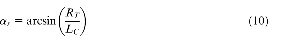
The problem of tool collision, which is referred to as the printing head tool collision and the cutting tool collision in this article, will inevitably be addressed in the sequence planning of five-axis hybrid manufacturing. In order to avoid tool collision, a method to ensure the tool accessibility should be provided. The tool accessibility at any particular contact point should enable the accessibility of the printing tool and the cutting tool without collision. The requirements to achieve this can be characterized by the corresponding tool accessibility range (TAR), which represents the ability of the tool to obtain a continuous toolpath at the contact point.
Many scholars have studied the calculation methods for tool accessibility. Choi et al. 20 proposed a method to obtain the TAR by mapping obstacles and machine tool constraints to a two-dimensional configuration space. Balasubramaniam et al. 21 presented a visualization-based method to capture the TAR in a three-dimensional Cartesian space. Wang and Tang 22 proposed a fast TAR calculating method based on the assumption that the TAR varies smoothly along the toolpath. Aiming at blisk machining, Chen et al. 23 proposed a TAR calculation method using the tool reference plane. Liang et al. 24 introduced a boundary-based TAR calculation method, in which each obstacle surface was simplified as a boundary curve.
The above methods are only suitable for traditional cutting processes. For complex hybrid manufacturing process, the TAR calculation method should evaluate the dynamic five-axis movement capability of machine tool as well as the possible combinations of multiple alternative printing and machining.
Definition of tool accessibility based on Gaussian Sphere
For any particular tool contact point Pi on the part surface, in order to describe the tool accessibility, a unit hemisphere called a Gaussian Sphere can be attached at this point. Each point on the Gaussian Sphere represents one tool axis direction at Pi. Meanwhile, there is a specific continuous area on the sphere indicating the TAR at that point and the other area indicating the tool non-accessibility range (NTAR), as shown in Figure 1. For the additive process, the region is called printing accessibility range (PAR), which is used to characterize the accessibility of the printing tool. Similarly, for the subtractive process, the region is called cutting accessibility range (CAR), which is used to characterize the accessibility of cutting tool.
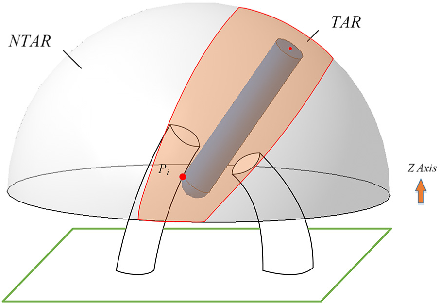
Diagram of Gaussian Sphere.
Printing accessibility
Taking printability into consideration, the whole printing process should be free of collision and free of requirements for auxiliary support. Therefore, the PAR at a certain point can be expressed as the intersection of the non-collision range (NCR) and the self-supporting accessibility range (SAR) as follows

In the additive process, the self-supporting printing can be realized by limiting the printing direction. Specifically, for the current printing layer, as shown in Figure 2, the normal vector
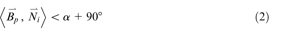
In the formula,
The self-supporting accessibility range (SAR).
The points around the contour of each printing layer are used to measure the PAR for that layer. For the current printing layer Lj, the contour is discretized into n points by a minor step size σ. The PAR at each point can be calculated and the intersection of all the ranges represents the PAR on the current printing layer, as follows

If the printing direction of the current printing layer
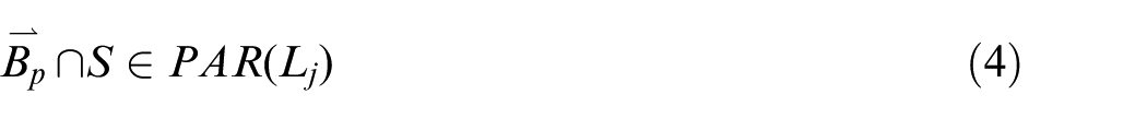
This means that the current layer Lj is printable along this printing direction; otherwise, the printing direction must be adjusted to satisfy the above relationship.
Cutting accessibility
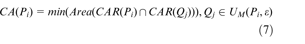
Considering that the cutting tool vector for each point Pi is not fixed under the five-axis mode, so the cutting accessibility (CA) can be defined as the area of the cutting accessibility range (CAR), as follows

There is no reason for calculating the CAR at any point of parts, because the tool must move continuously, which means that it is necessary to calculate the neighborhood CAR of the contact point in any direction,
19
to meet the requirements of collision-free. Given a minor step size

In the above formula,
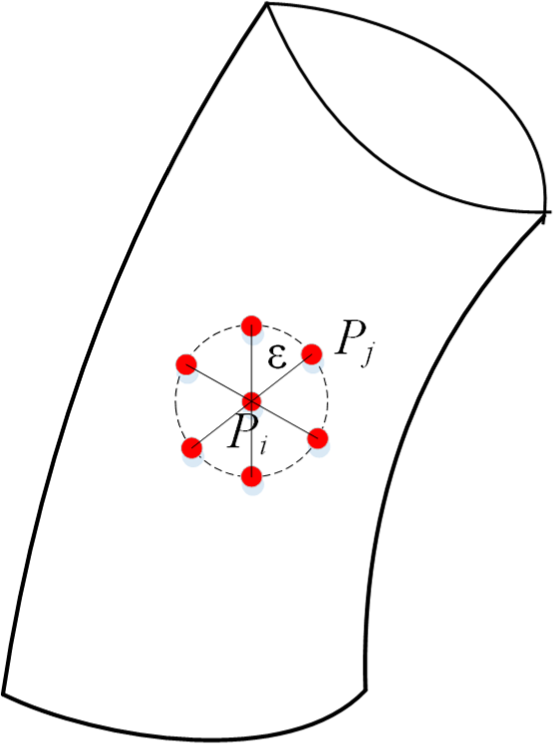
Diagram of contact point neighborhood.
Based on the above definition, a more precise definition can be given for cutting accessibility at a certain contact point Pi as follows
Given a printing layer Lj, the cutting accessibility of the contour is what needs to be known. The contour can be discretized into several points by a minor step size

Calculation method of multi-tool accessibility based on light projection
Based on the above definitions of printing accessibility and cutting accessibility, it is vital to find an effective way to calculate multi-tool accessibility. Intuitively, the TAR is analogous to the visible range of light projection. Accordingly, the contact point can be regarded as a light source and the blocking part will project a shadow on the Gaussian Sphere. Consequently, the bright area on the Gaussian Sphere represents the TAR.
For a given facet Fi on the part Standard Triangle Language (STL) model, a vector
And, the continuous boundary of the bright surface is the light–dark boundary, as shown in Figure 4.
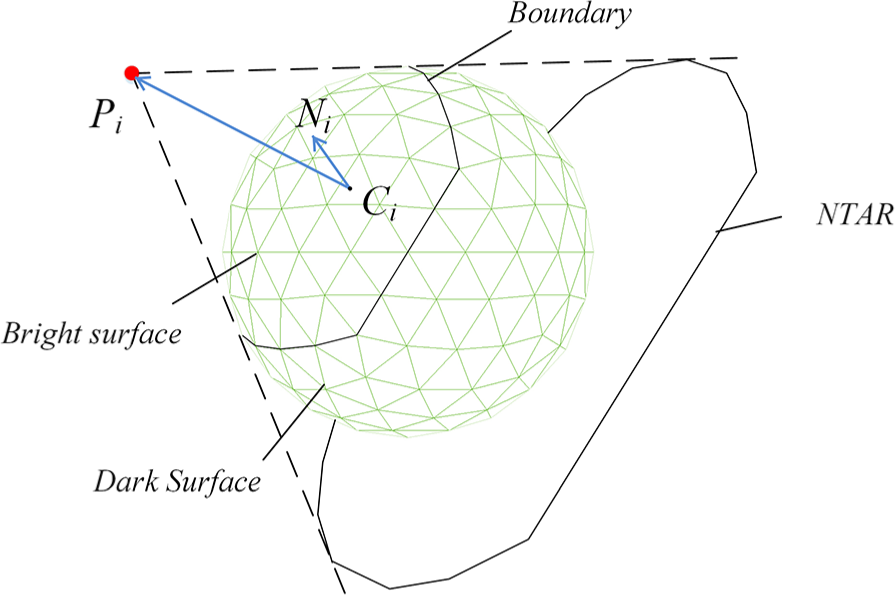
Diagram of light projection.
When using the light projection method, it is relatively simple to calculate the TAR by deeming the light source as a light point. While the calculation process needs to be further modified in the actual machining process as the existing of tool radius. For the cutting process, considering that the cutting direction is variable, the ball-nosed end milling is generally used to keep the reference point of the tool (which lies on the tool axis) unchanged. For the printing process, the structure of the printing tool is relatively complex, so the model needs to be simplified accordingly for the calculation convenience. The printing tool can be simplified as a cylinder with a certain radius and the lower printing head can be simplified as a cone connected with the cylinder.
In addition, it is necessary to offset the point source by an angle
where
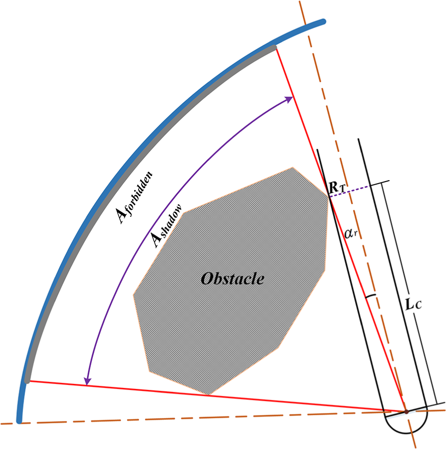
Diagram of light projection modification based on tool geometry.
The proposed sequence planning method of hybrid manufacturing
Modeling of sequence planning
Under the hybrid alternative additive–subtractive manufacturing mode, it is necessary to divide the part into several elements, that is, subcomponents, so as to define a non-interference and support-free forming process plan for complex structural parts. Taking time efficiency into consideration, too frequent cutting tool changes will increase operation time, which would seriously affect the manufacturing efficiency of the whole part. Therefore, for hybrid manufacturing of complex structural parts, taking non-interference and support-free as two constraints, the sequence planning problem can be defined as an optimization problem, which aims to maximize the operation efficiency. Based on the above analysis, the sequence planning problem can be modeled as following
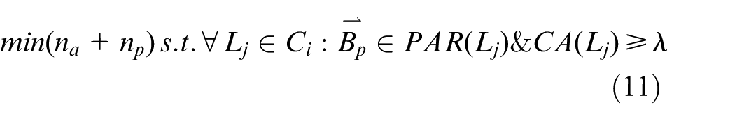
where na denotes the number of changes from additive to subtractive process, np denotes the number of printing segments, Lj denotes the current printing layer of subcomponent Ci, and λ denotes a minimum value of CA. Generally, in order to satisfy the continuity of the toolpath, the tool should be able to move at least one cutter location during the machining process, as shown in Figure 6. The value of
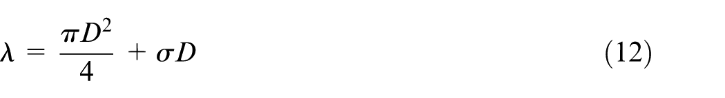
where D denotes the tool diameter and
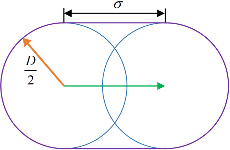
Diagram of the minimum envelope area.
Decision-making on initial printing directions and volume decomposition
In order to address the problem of decision-making on initial printing directions, an iterative search–based algorithm is proposed. Before giving an explanation of the algorithm, it is necessary to establish an assumed structure of the part. The concept of “column” presented by Chen et al. 19 is used here. Based on the concept “column,” the process of decision-making on initial printing directions and volume decomposition is described in Algorithm 1.
Iterative search–based decision-making of initial printing direction
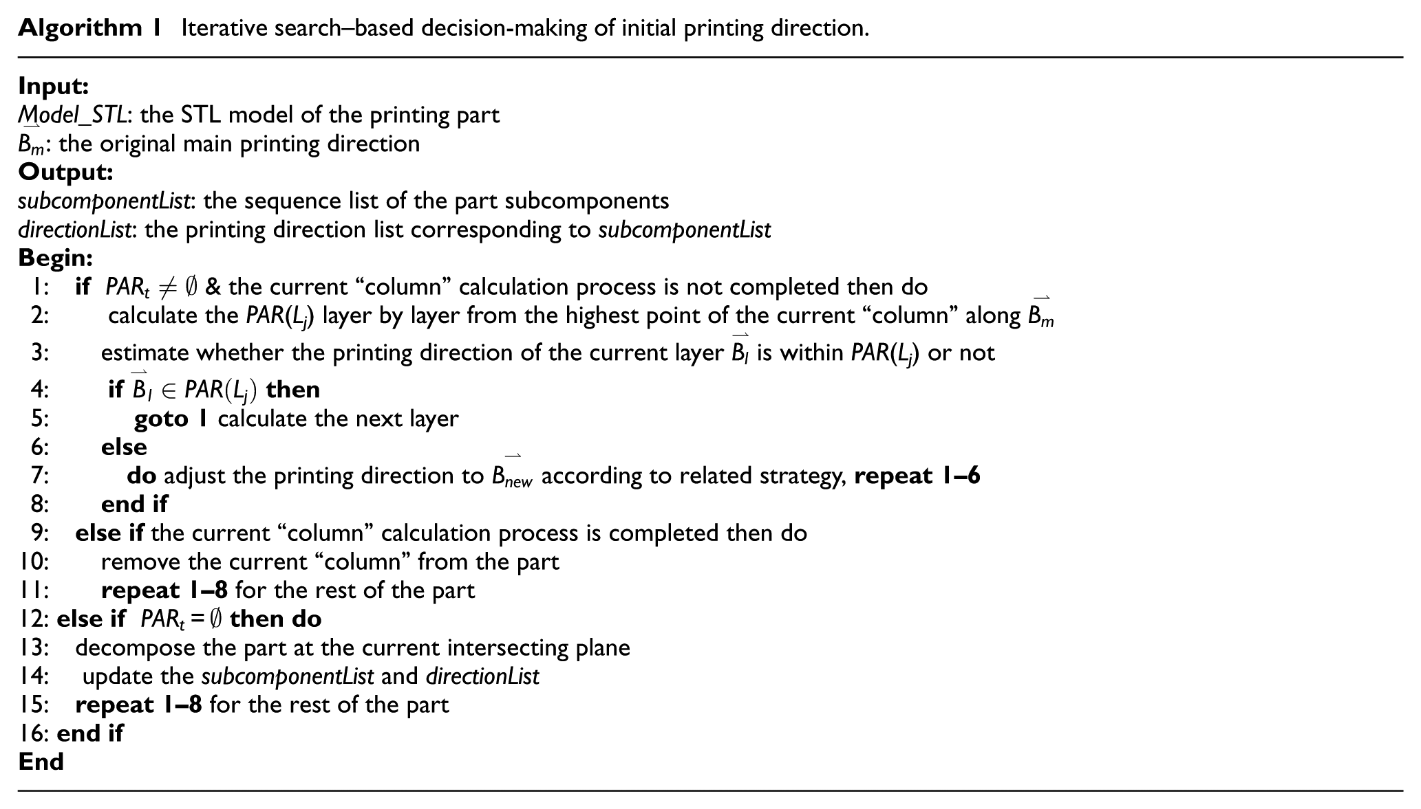
The printing direction adjusting strategy follows the rule: calculate the centroid Pc of the total printing accessible range
In the process of iterative search for the printing direction, the part is decomposed by the positions which do not meet the printing collision condition and the initial printing sequence can be obtained according to the decomposition order. So far, the effect of cutting accessibility has not been considered, so only an initial alternative sequence of hybrid manufacturing is obtained. For the ith subcomponent, if Ai denotes the corresponding additive process, Si denotes the subtractive process, the initial alternative sequence can be expressed as
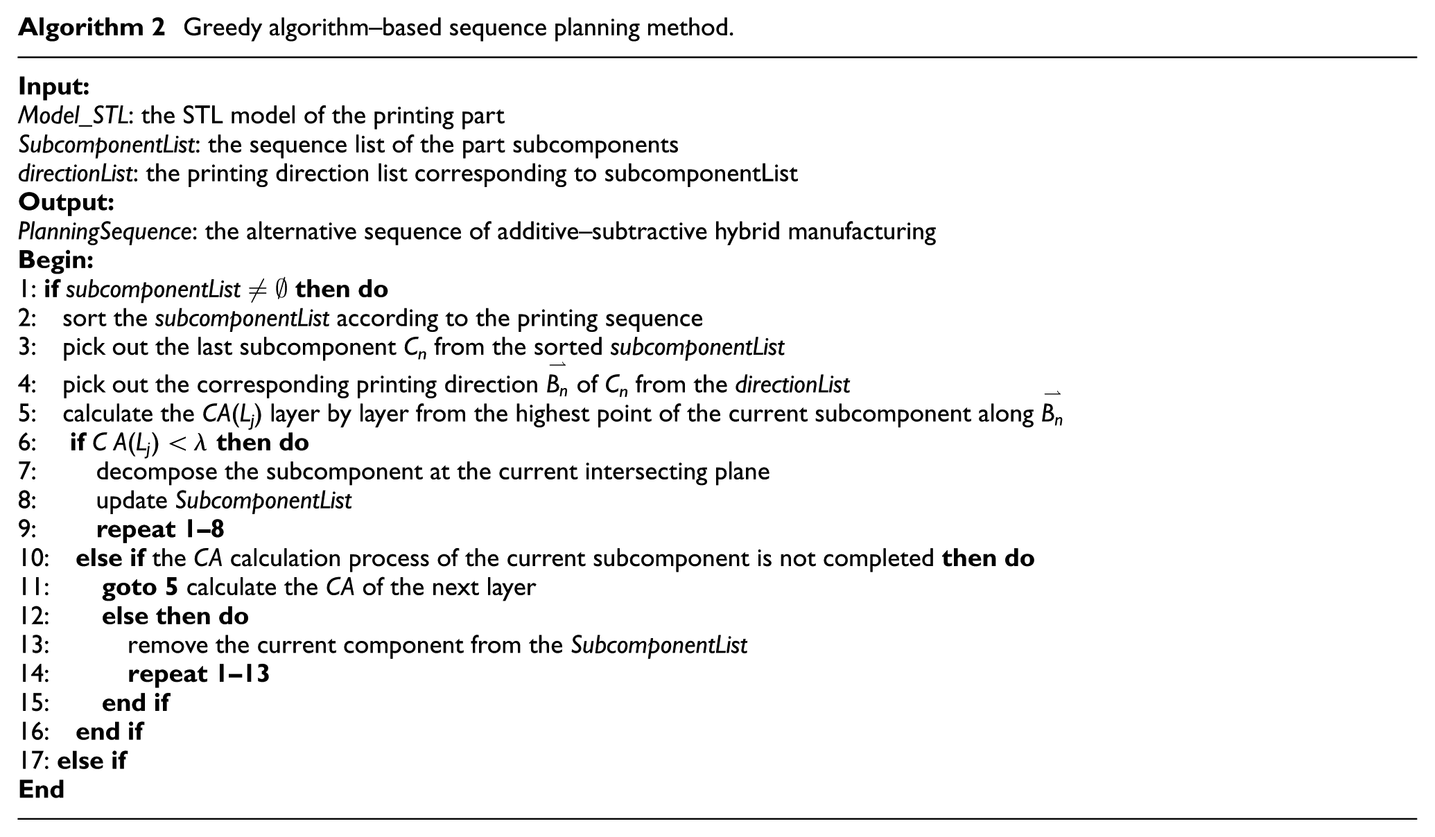
Sequence planning method based on a greedy algorithm
Based on the results of the initial printing direction decision-making and volume decomposition, a greedy-based algorithm is proposed to address the sequence planning problem of hybrid manufacturing.
The initial hybrid manufacturing sequence is the alternative additive–subtractive process, which is in the form of
The greedy algorithm–based sequence planning method is described in Algorithm 2, and the time complexity of the proposed algorithm is
Greedy algorithm–based sequence planning method
Case study
In order to further explain the sequence planning method proposed in this article, the part model shown in Figure 7 is taken as an example to introduce the method in detail.
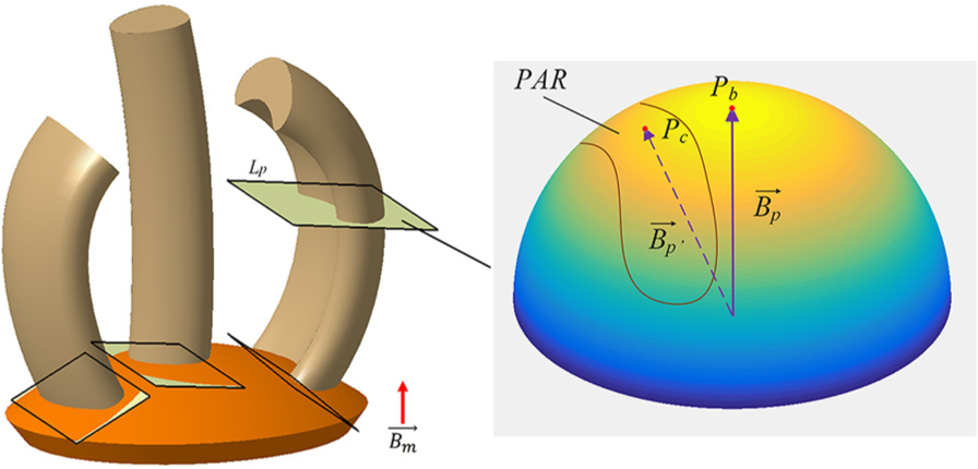
Diagram of adjusting printing direction.
It can be easily observed that this part consists of three “column” structures. First, an original main printing direction
For the current “column,” the iterative searching steps are executed along the new printing direction
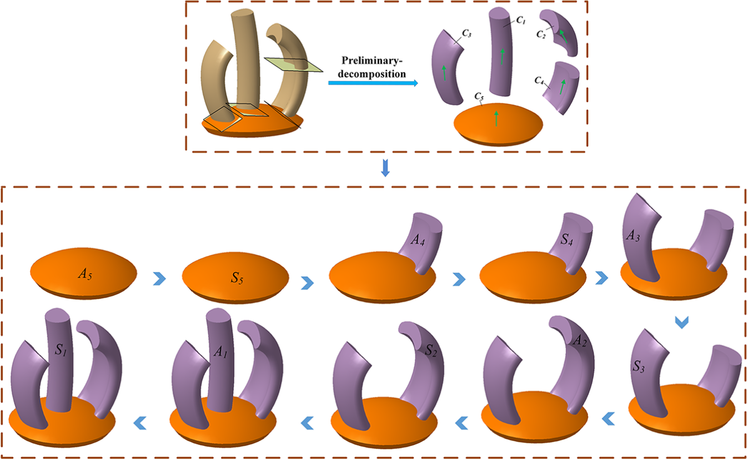
The initial alternative sequence of hybrid manufacturing of part 1.
For the example part model, the initial alternative sequence is obtained, so the accessibility calculation is started from the last subcomponent C1. For the subcomponent C1, the body is sliced from the top to bottom and the accessibility of each slice contour is calculated according to its printing direction
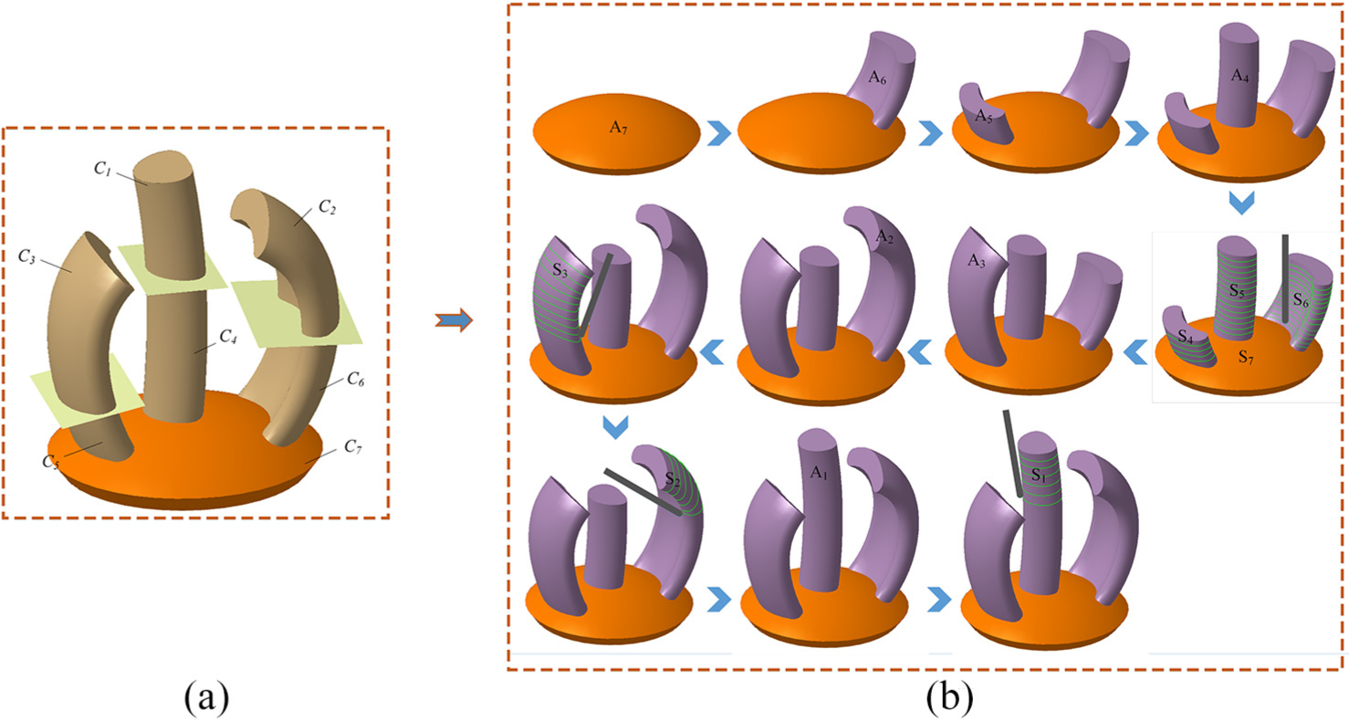
(a) The final decomposition of part 1 and (b) the final alternative sequence of hybrid manufacturing.
Another part model is also selected as an example to illustrate the feasibility of the proposed method. Similar to the first example, an initial alternative sequence of hybrid manufacturing is obtained in the direction decision stage:
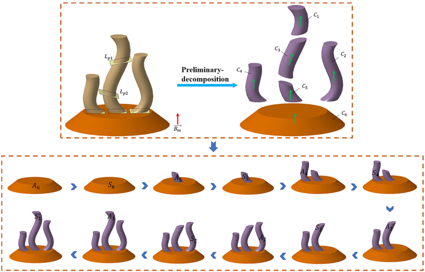
The initial alternative sequence of hybrid manufacturing of part 2.
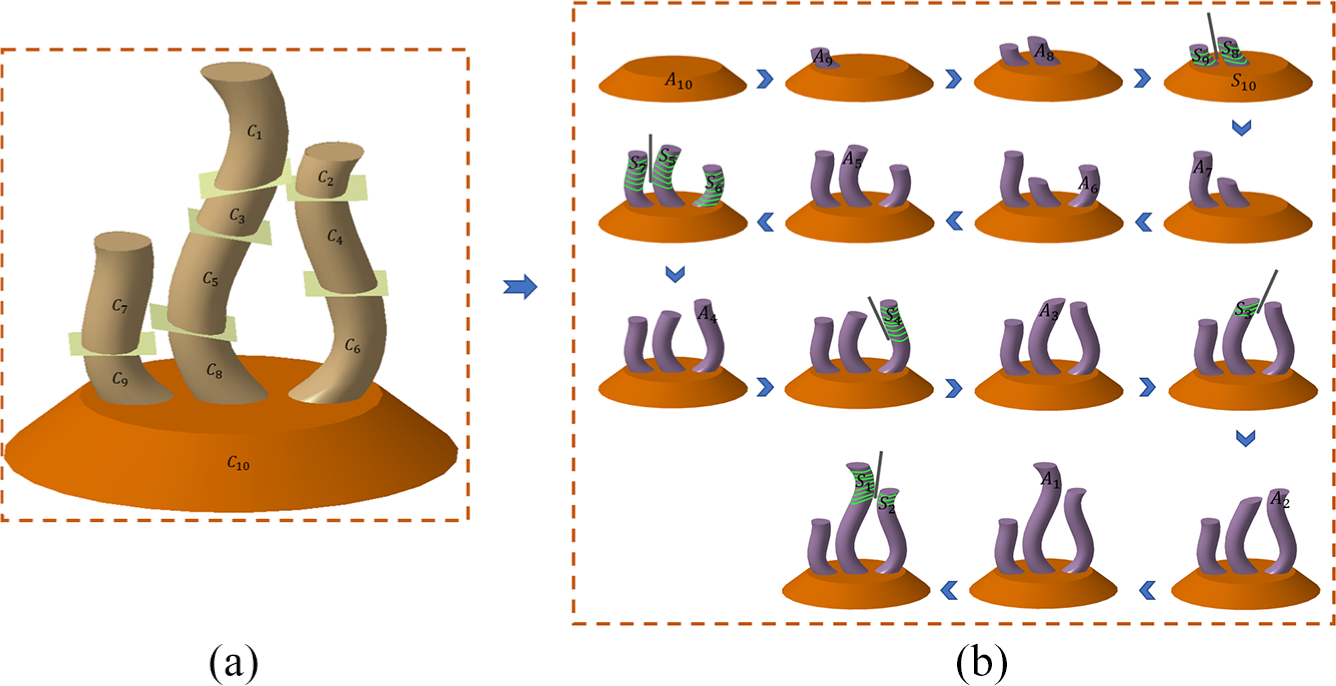
(a) The final decomposition of part 2 and (b) the final alternative sequence of hybrid manufacturing.
It can be found that, using the proposed method, some additive process layers can be continuously performed and then followed by a cutting process. If the proposed method is not used, the smallest layer height would be set normally, and the sequence would be always additive process and cutting process switched after each small layer, which would be very time-consuming.
It should be stated that the “columnar feature” mentioned in this article is an abstraction of the part geometric feature, so the method proposed in this article can also be feasible to other types of geometries which can satisfy the definition conditions of “columnar feature.”
Conclusion and future work
In order to bridge the research gap of the sequence planning issues of five-axis hybrid additive–subtractive manufacturing, a sequence planning method for high-precision complex structural parts has been described in this article. The whole planning of hybrid manufacturing sequence was realized based on greedy algorithm, where the coupling relationship between printing direction and accessibility calculation was solved by an iterative search algorithm.
This method provides a novel approach to sequence planning for hybrid manufacturing, which has the potential to greatly reduce the tool changing time as well as identify an effective additive–subtractive sequence for complex part production. While this work was an initial study in sequence planning, it laid a foundation for the realization of highly efficient hybrid manufacturing.
Although the proposed method has a good application prospects, there is still a lot of room for improvements. The research outcomes have not been applied to actual processing yet. For the convenience of calculation, the tool was simplified in the algorithm, while real printing head tool and cutting tool are much more complicated. Therefore, more optimized algorithm will be considered to solve complex collision and other problems in the future.
Footnotes
Declaration of conflicting interests
The author(s) declared no potential conflicts of interest with respect to the research, authorship, and/or publication of this article.
Funding
The author(s) disclosed receipt of the following financial support for the research, authorship, and/or publication of this article: The reported research was funded by the National Science and Technology Major Project of China (2015ZX04001002).