
Abstract
Additive manufacturing has been developed for decades and attracts significant research interests in recent years. Usually, the stereolithography tessellation language format is employed in additive manufacturing to represent the geometric data. However, people gradually realize the inevitable drawbacks of the stereolithography tessellation language file format, such as redundancy, inaccuracy, missing of feature definitions, and lack of integrity. In addition, it is almost impossible to apply the simple polygonal facet representation to the five-axis manufacturing strategy. Hence, there are quite few researches and applications on the five-axis additive manufacturing, in spite of its common applications in the subtractive machining. This article proposes a feature-based five-axis additive manufacturing methodology to enhance and extend the additive manufacturing method. The additive manufacturing features are defined and categorized into two5D_AM_feature and freeform_AM_feature. A feature extraction method is proposed that can automatically recognize the additive manufacturing features from the input model. Specially for the freeform_AM_feature, a five-axis path planning method is proposed and split into three stages: (1) offset the reference surface, (2) spatially slice the freeform layers, and (3) generate the toolpaths for each freeform layer. Real additive manufacturing five-axis toolpaths can be obtained using the proposed algorithm that performs as a secondary developed plug-in in the CATIA® environment. A robotic additive manufacturing system is constructed for the implementation of the five-axis additive manufacturing tasks, which are generated by the proposed algorithms and post-processed after simulation and off-line programming. Some examples are printed to validate the feasibility and efficiency of the proposed method.
Keywords
Introduction
Recently, additive manufacturing (AM), derived from rapid prototyping (RP), has attracted great interests in many fields, such as art, medical, educational, automotive, and aerospace industries.1,2 It is capable of building complex parts directly from computer-aided design (CAD) models by accumulating the plastic or metal materials layer by layer. Compared to conventional manufacturing methods, AM can save time and material in prototyping and producing complex shapes. For this reason, it has expanded rapidly since mid-1980s. And various AM processes have been invented and promoted for the industrial applications. According to the ISO 17296-2, 3 different AM technologies are classified into seven categories, as listed in Table 1. Each of these technologies has its available materials and limits and thus is used in its corresponding fields respectively. Generally, AM could help factories shorten the product life cycle and save the costs. Therefore, it has been considered to be an evolution of traditional manufacturing technologies.4,5
Classification of different AM technologies.
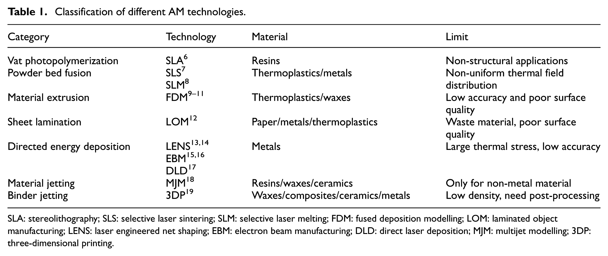
SLA: stereolithography; SLS: selective laser sintering; SLM: selective laser melting; FDM: fused deposition modelling; LOM: laminated object manufacturing; LENS: laser engineered net shaping; EBM: electron beam manufacturing; DLD: direct laser deposition; MJM: multijet modelling; 3DP: three-dimensional printing.
Nowadays, AM processes are mostly implemented in 2.5-axis in which the accumulating layers are planar, produced by the slicing algorithm with a number of planes parallel to the build platform. 20 In these 2.5D AM processes, the stereolithography tessellation language (STL) format is used to represent a part model. However, the STL file format can bring many inevitable drawbacks, such as redundancy, inaccuracy, and lack of integrity,21,22 and it is almost impossible to implement the five-axis manufacturing strategy without explicitly defined features.
Recently, the five-axis strategy is used in AM to reduce support structures and is proved to be effective. Singh and Dutta23,24 proposed a multi-direction slicing method to improve the surface quality and minimize the support structure. Adaptive slicing technology proposed by Zhang and Liou 25 can change the slicing direction according to the normal vectors of the solid surface. Dwivedi and Kovacevic 26 developed algorithms to derive the skeleton of a complex part so as to deduce the building directions. Ding et al. 27 reported a decomposition–regrouping method to determine the slicing directions of different sub-volumes.
Although the above studies aimed to achieve the five-axis manufacturing, path planning is merely 2.5D, as the slicing layers are mostly planar and oriented in the same direction. The planar slicing layers result in stair-step effects for curved surface, influencing the part quality. On the other hand, curved-layer slicing is proved to improve surface quality and reduce the number of layers in specific cases. 28 Therefore, it will be meaningful to implement five-axis curved-layer slicing strategy which can reduce support structures and improve surface quality. In fact, even if the tool axis varies along the toolpaths, it is almost impossible to fully take the advantages of five-axis AM without detailed information of geometric features in the file in STL format, such as the definition of freeform surface. For this sake, the analytical models, such as the STEP format, must be employed in AM to represent the geometric features.
Feature-based method has been widely used in CAD and computer-aided manufacturing (CAM) to express the designing intents and design the milling strategies. On the contrary, there are quite few researches on the applications of feature-based method in AM. Recently, the use of AM features is proposed by Zhang et al. 29 for the decision-making of the process planning for AM. However, only the building orientation for the path planning of 2.5D AM is considered in their study. The definition of AM features is proposed containing both geometrical form and technological attributes related to AM in the research of Van Thao and Mandil, 30 but no detailed information about the AM features is presented in the study.
This article proposes a feature-based five-axis AM methodology. The geometrical information of AM features and the path generating method are the main consideration. Considering different printing conditions, AM features are categorized into two5D- and freeform AM features, where the former one can be considered as the summary and abstraction of the existing AM methods, and the latter one is specially proposed for the freeform five-axis AM using analytical data models. Generally, the freeform five-axis AM is split into three stages: offset the reference surface, spatially slice the freeform layers, and generate toolpaths for each layer. The proposed algorithms are integrated into the CATIA® V5R19 environment as a plug-in based on Component Application Architecture, CATIA API (Dassault Systems), which can generate the expected five-axis toolpaths. Subsequently, a robotic AM system is established to test the toolpaths, which in advance were simulated and off-line programmed by a robot simulation system. Exemplary workpieces have been printed using the proposed algorithms and developed systems, which verify the feasibility and efficiency of the five-axis AM method.
Feature-based AM
In the conventional AM, no matter how complicated the part geometry is, the manner of building layer by layer is almost the same for any parts. However, with the feature-based AM, a part is composed of AM features, and thus, there is more flexibility to build the part, bringing more advantages as follows:
Much more useful information can be contained in the AM features of a part than the model described as a whole by the STL format. As the geometry information is essential to determine the building parameters, such as the building orientation, 29 layer height, the information of the AM features can help the users to determine the strategies for the AM process.
For the features of a part to be built, the manufacturing parameters could be variable, such as different layer heights, different path patterns, and different precision, even different material, which provides a way to optimize the AM process to obtain better performance of a part, surface quality for example.
As a part is built in the sequence of the part’s AM features, it is easy to perform hybrid manufacturing. Other manufacturing technologies, such as machining, could be implemented between the AM processes of every two features to achieve a high-quality part.
Compared to the conventional building manner of printing the whole part, it would save time by building a complicated part from existing ones. Besides, it may bring the convenience of some work, such as the task of component repair. Actually, the use of AM in the work of repairing titanium components has been explored in aerospace. 31 It is much easier to realize the repairing process with the component to be repaired as a feature of the whole part.
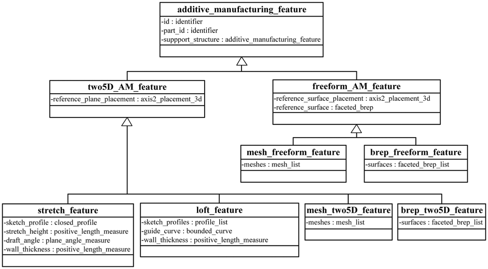
In the majority of cases, the features lie on planar surfaces, which can be built with 2.5D AM toolpaths. However, in other cases, the features may grow from existing curved surfaces and are more suitable to be built by five-axis strategy. Therefore, AM features are categorized into two5D_AM_feature and freeform_ AM_feature, as shown in Figure 1.
AM features.
Abstract layer of the AM feature
As known to all, the material is gradually accumulated to form different blocks along with the AM process, which is different from the one of traditional machining technologies beginning with the blank material. According to this characteristic of AM, the AM feature should be a volumetric region, like the additive manufacturable element described by Rosen. 32
An AM feature refers to a solid shape feature specified by designers, users, or AM process planners that has significant functions to a part and carries the detailed geometric information which is helpful for the AM process. The configuration of all the geometric AM features is shown in Figure 1. The additive_manufacturing_feature entity is the abstract supertype of all features. It includes the basic attributes of AM as follows:
id: the identifier of the feature.
part_id: the part id which the feature belongs to.
support_structure: the support structure for the suspended features. It is also an AM entity if exists. Otherwise, it is null.
Two5D AM feature
As shown in Figure 1, the two5D_AM_feature is one of the two subtype features of the additive_manufacturing_feature. For this type of feature, the feature grows from a plane that all the planar accumulating layers are parallel to this plane. Hence, the base plane, named reference plane in this article, is a key property for the two5D_AM_feature. To specify the reference plane and the local reference coordinate system of the feature, the reference_plane_placement item is need, which is a matrix donating the rotation and translation of the local reference coordinate system corresponding to the global coordinate system. If the matrix is identical, the coordinate system is the same as the global coordinate system and the reference plane lies on the X-Y plane.
For the two5D_AM_feature entity, there are a few basic subtype features that may be often used on the part design stage, as shown in Figure 2. They are stretch_feature, loft_feature, mesh_two5D_feature, and brep_two5D_feature. Besides, for the stretch_feature and loft_feature, the mathematical expression for the contours of all layers can be obtained via the definition parameters of the features, so that there is no need to compute the intersections of the reference plane and the feature surfaces which are time-consuming and error prone.
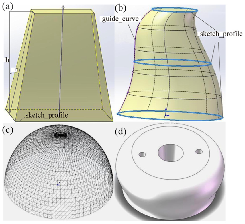
Two5D AM features: (a) stretch_feature, (b) loft_feature, (c) mesh_two5D_feature, and (d) brep_two5D_feature.
The detailed introduction of the four features is as follows:
1. Stretch_feature
The stretch_feature entity is defined as a planar profile lying on the reference plane, that is, the z = 0 plane in the local coordinate system, that stretches along the z-axis, as shown in Figure 2(a). The sketch_profile parameter describes the profile to be stretched and the stretch_height parameter determines the length of the stretch solid. If the sides of the feature are not vertical to the reference plane, the draft_angle is used to represent the draft angle value. If it is positive, the solid shrinks inward when the feature grows toward the z direction; otherwise, it expands outward. In addition, if the stretch_feature is a shell solid, the wall_thickness parameter defines the thickness of the wall, or else the parameter is zero.
2. Loft_feature
Considering the two5D AM process, the loft_feature entity is simplified as a solid that connects a series of profiles lying on parallel planes, along a guide curve, as shown in Figure 2(b). The section profiles are contained in the sketch_profiles list, and the guide_curve is used to control the trend of the solid shape. Similar to the stretch_feature, the wall_thickness parameter determines the thickness of the shell solid feature.
3. Mesh_two5D_feature
The mesh_two5D_feature is used when the feature geometry is described by meshes which does not require high precision, as shown in Figure 2(c), and usually refer to triangle mesh which is now widely used in 2.5D AM in the STL format. Different from the above two features, there is no historical information of the modeling process of the feature geometry.
4. Brep_two5D_feature
Except for the features discussed above, other two5D AM features are classified as the brep_two5D_feature. The geometry of this feature is expressed by the B-Rep surfaces of the solid described in the surfaces parameter which is more accurate than the mesh_two5D_feature.
Freeform AM feature
While the two5D_AM_feature lies on a planar surface (the reference plane), the freeform_AM_feature is located on a curved surface. As the geometry of this kind of feature is too complicated to be directly described by the CSG modeling parameters similar to the AM accumulating process, it can be uniformly described by the B-Rep surfaces contained in the surfaces parameter as brep_freeform_feature, or described by the meshes contained in the meshes parameter as mesh_freeform_feature. The reference_surface parameter is the basic freeform surface of the accumulating layers, and the reference_surface_placement determines the local coordinate system of the surfaces or the meshes.
Feature-based AM path planning process
Based on the AM feature definitions, the geometry model of a part can be further defined as the group of a series of AM features, such as an impeller and a reentry capsule (shown in Figure 3). As shown in Figure 4, the impeller model is composed of a hub feature and six blade features, which the hub feature is a brep_two5D_feature while the blades are brep_freeform_features. Similarly, for the reentry capsule, there are four features (as shown in Figure 4) that feature1 is a brep_two5D_features, while feature2, feature3, and feature4 are brep_freeform_features.
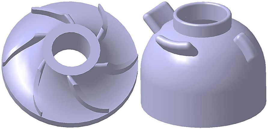
Impeller and reentry capsule model.
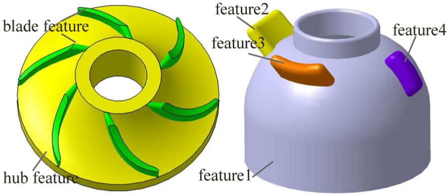
AM features of the impeller and reentry capsule.
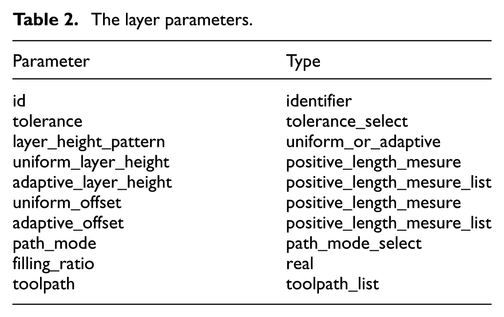
Besides the geometric data, other information is also important to define a part. In this article, most interests are focused on the information related to the AM path planning process. Since the layer concept is a key point in AM process, the parameters of the layer_parameter entity as shown in Table 2 which describes the parameters of one layer contribute to guiding the procedure of slicing and path generating for each feature. Considering the layer-by-layer AM process, the layer_parameter entity consists of the following items:
id: the identifier of the entity.
tolerance: optional parameter for the manufacturing dimensional tolerance of the feature. In some cases, the result of AM is a workblank of other manufacturing processes, such as in the additive and subtractive manufacturing process, in which the tolerance donates the machining allowance for the following post-process.
layer_height_pattern: it could be uniform or adaptive. If it is uniform, the layer height and path offset value are determined by the uniform_layer_height item and uniform_offset item, respectively, which, namely, all the layers share the same layer height and path offset value. While in some other cases, for example, to obtain better surface quality, the layer height can be adaptive, 33 changing with the feature surfaces conditions. Then the adaptive_layer_height and adaptive_offset can be used to describe the values of the layer height and path offset.
uniform_layer_height: the uniform layer height value of the uniform layer_height_pattern.
adaptive_layer_height: the layer height values of different layers used in adaptive layer_height_ pattern.
uniform_offset: the uniform path offset value of the uniform layer_height_pattern.
adaptive_offset: the adaptive path offset values corresponding to the adaptive layer height values of the adaptive layer_height_pattern.
path_mode: the path generation mode. It can be raster, zig-zag, contour, or other path generation modes.
filling_ratio: the filling percentage of the inner part.
tool_path: the generated toolpaths in the local coordinate system, taking all the parameters above into account.
The layer parameters.
Therefore, the process that a part is generated after all its features have been made in order is considered as feature-based AM, and the procedure of its path planning is shown in Figure 5. For each feature, its layer parameters are determined by the layer_parameter of the feature. Then, for different types of features, the contours of the accumulating layers are computed accordingly.
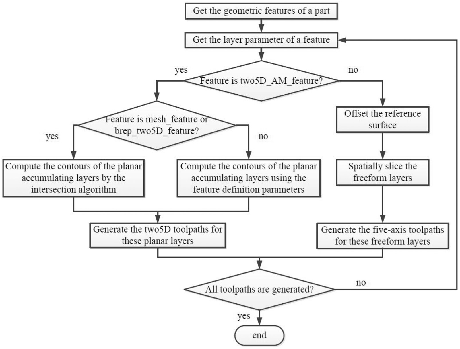
The feature-based AM process.
For the stretch_feature, as the stretch direction is vertical to the reference plane, the contour of every layer is similar to the base profile, and its contour is determined by the draft_angle value. Obviously, if the draft_angle value is zero, the contour of each layer is the same except for the z coordinate value of the profile, or else it is the offsetting result of the sketch_profile. Therefore, the contour of a layer can be uniformly calculated as

where
For the loft_feature, the contour of a certain layer is one of the section profiles or the interpolation of two adjacent profiles 34 which can be directly calculated with the feature’s definition parameters. As to the other two two5D AM features, mesh_two5D_feature and brep_two5D_feature, since there is no historical information of modeling process about the feature geometry, no uniform contour information of a layer can be obtained directly, therefore leading to the fact that the intersection computing is unavoidable. Note that as the mesh model is an approximation of the theory model, there is error between the contour computed by the intersection algorithm and the theoretical contour. If the feature is freeform_AM_feature, the accumulating layers and contours are generated by the procedure of spatially slicing the freeform layer.
After that, the two5D paths are generated on the planar accumulating layers of the two5D features, while for the freeform AM features, the five-axis paths are generated on the freeform accumulating layers. The path generation method for the two5D AM features is the same as the one of traditional 2.5D AM except that the slicing plane is parallel to the reference plane, which leading to the fact that the tool direction is vertical to them. Finally, the path planning process is ended with the toolpaths generated for all features.
For the proposed feature-based AM method, the features are classified into two groups according to the reference surface. The mesh_two5D_feature and the brep_two5D_feature are similar to the traditional 2.5D AM except that the slicing planes are orientated and not limited to the planes vertical to the z-axis of the global coordinate system any more. As the other two basic features have the modeling process similar to that of the AM, the contour of a given layer could be expressed by the feature’s CSG modeling parameters which is closely related to the modeling process. Therefore, lack of intersection in the slicing procedure makes it more accurate for the contour information. Particularly, for the freeform features, the characteristic lies in the freeform layers accumulated by the five-axis toolpaths.
Extraction of AM features
Practically, the AM features need to be extracted automatically using some feature identification algorithms. For this consideration, a set of function blocks for extracting and recognizing AM features from a B-Rep (Boundary Representation) model are developed. In the Standard for the Exchange of Product Model Data (STEP) (AP 203 or AP 214)35,36 standard, a workpiece is usually represented using a shell consisting of a set connected faces and some loops of edges defining the face boundaries.
The feature extraction algorithm strongly relies on the concavity of the loop of edges. Figure 6(a) presents the concave and convex edge examples defined in the study of Fu et al.
37
Literally, an edge is concave when the external edge angle of its two adjacent surfaces is less than
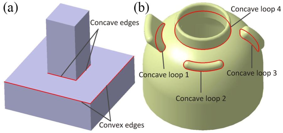
Concave edges and concave loops: (a) concave and convex edges of a model and (b) concave loops of a model.
The flowchart of the feature extraction algorithm of the extraction is shown in Figure 7. First, get the shell of the body. Next, find all the concave loops in the shell. If there exist concave loops, for each of the concave loops, find the shell containing the loop. Then split the shell by the loop and heal the split open shells. Finally, output all the split shells. Each shell represents the geometry of an AM feature. The capsule provides an exemplary workpiece to explain the principle of feature extraction in this section.
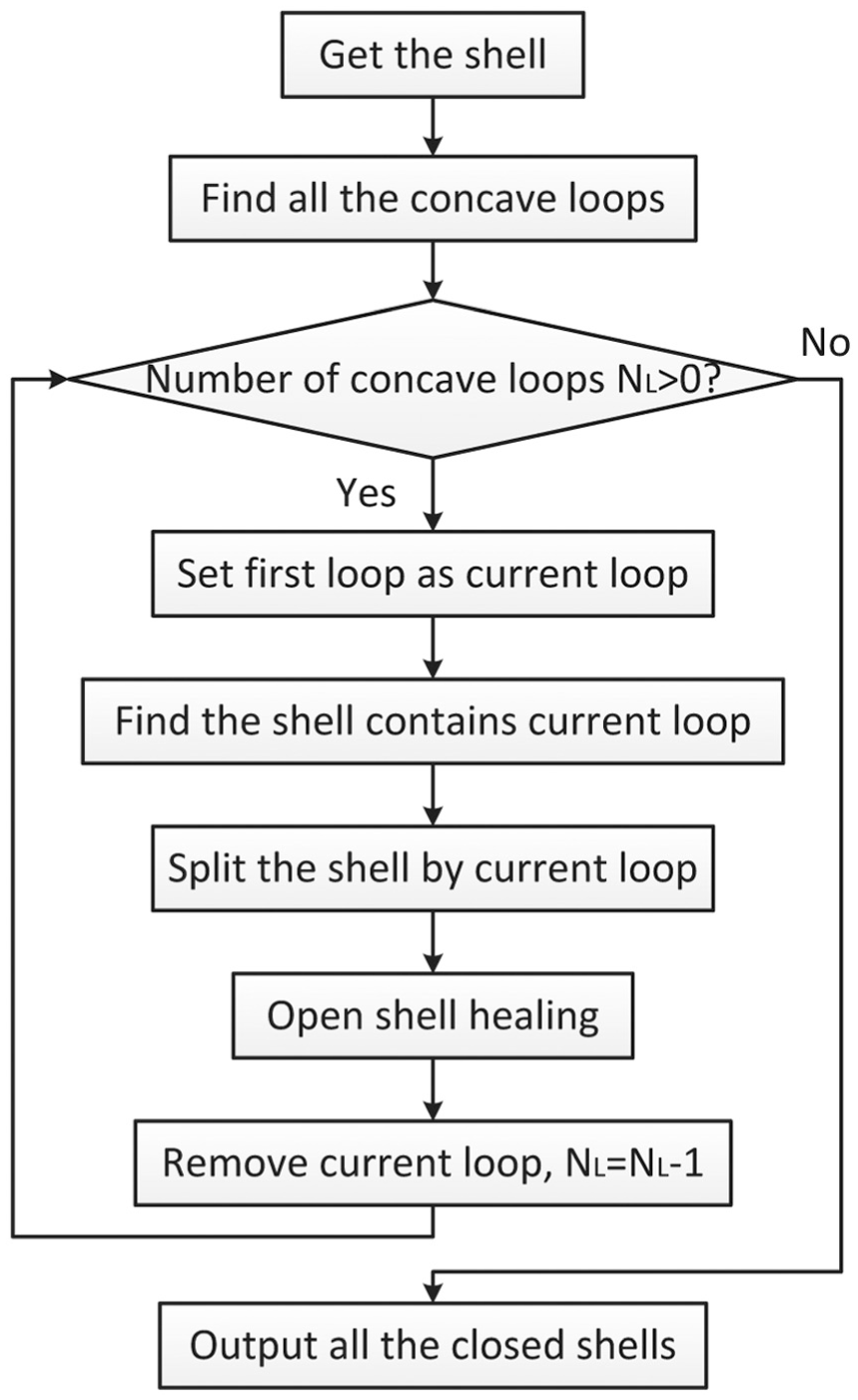
Flowchart of AM features extraction.
Shell splitting
Once all the concave loops are found, Figure 6(b) for the exemplary workpiece, the shell can be iteratively split for each concave loop:
Step 1. Convert the concave loop into an edge list
Step 2. Search the face that contains the first edge
Step 3. Search the faces that contain the first edge in
Step 4. Remove the first edge in
Step 5. Repeat Steps 3 to 4 until
Step 6. The shell is split into two face lists:
There are two cases of the final splitting results:
Case 1. Both of the two face lists are not empty, which means the shell is successfully split into two parts, as shown in Figure 8(a).
Case 2. One of the two lists is empty, which means the split process fails. The employment of the concave loop 4 in Figure 6(b) in splitting the shell would deliver this failure. Obviously, all the faces still can be connected together by the inside surface even if the concave loop cuts the outside surface. This happens in the cases that the genus 38 of the shell is not equal to zero. In such complicated cases, two or more loops should be considered to successfully split the shell. Moreover, to adapt the special need of extracting AM features, the loops may not exist in the original model. In this case, the shell still maintains as one in this study and the problem should be solved in the future work.
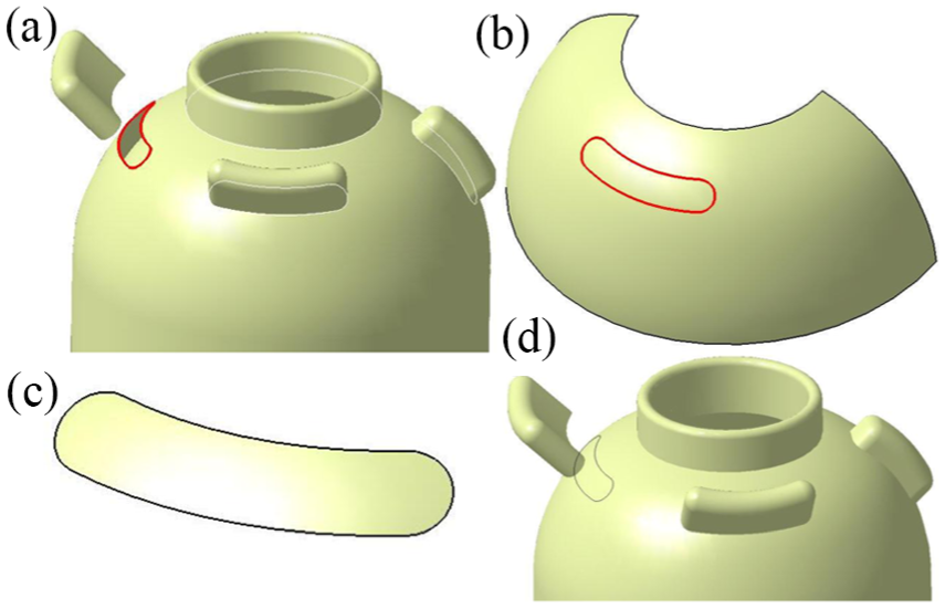
Shell splitting and open shell healing: (a) split one shell into two open shells, (b) original surface without trimming, (c) the trimmed area, and (d) healed shells.
Open shell healing
After the shell splitting procedure, the separated face groups individually contain several open shells, while a closed shell is necessary for the representation of solid features. For this reason, the open shells need to be healed automatically. This section proposes an open shell healing strategy according to the aforementioned splitting case 1.
In the first case, a shell is split successfully by a concave loop. Search for the face that contains the concave loop as shown in Figure 8(b) and extract the original surface without trimming. Then trim down the area within the projection of the concave loop out of the original surface, and the trimmed area is used to heal the two split shells, as shown in Figure 8(c) and (d). Besides, the original surface is set as the reference surface of the additive feature described by the closed shell that does not contain the searched face.
Through the shell splitting and shell healing procedures for every concave loop, the AM features of a part can be extracted. A feature is recognized as a brep_two5D_feature when the reference is a plane and is a brep_freeform_feature when the reference surface is a freeform surface.
Feature-based five-axis path planning methodology
Based on the definition of the freeform AM feature discussed above, a novel five-axis path planning strategy has been developed. For each feature to be built, the algorithm mainly includes three steps: offset reference surface, spatially slice freeform layers, and generate five-axis toolpaths.
Offset reference surface
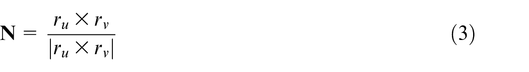
In the five-axis path planning strategy, the first step is offsetting the reference surface of the feature to be manufactured. As the reference surface of the feature has existed in the model, the offset surfaces can be generated by the offsetting algorithm based on the reference surface. The offset distance is the layer height of the accumulating layer. Suppose the reference surface is

where
where
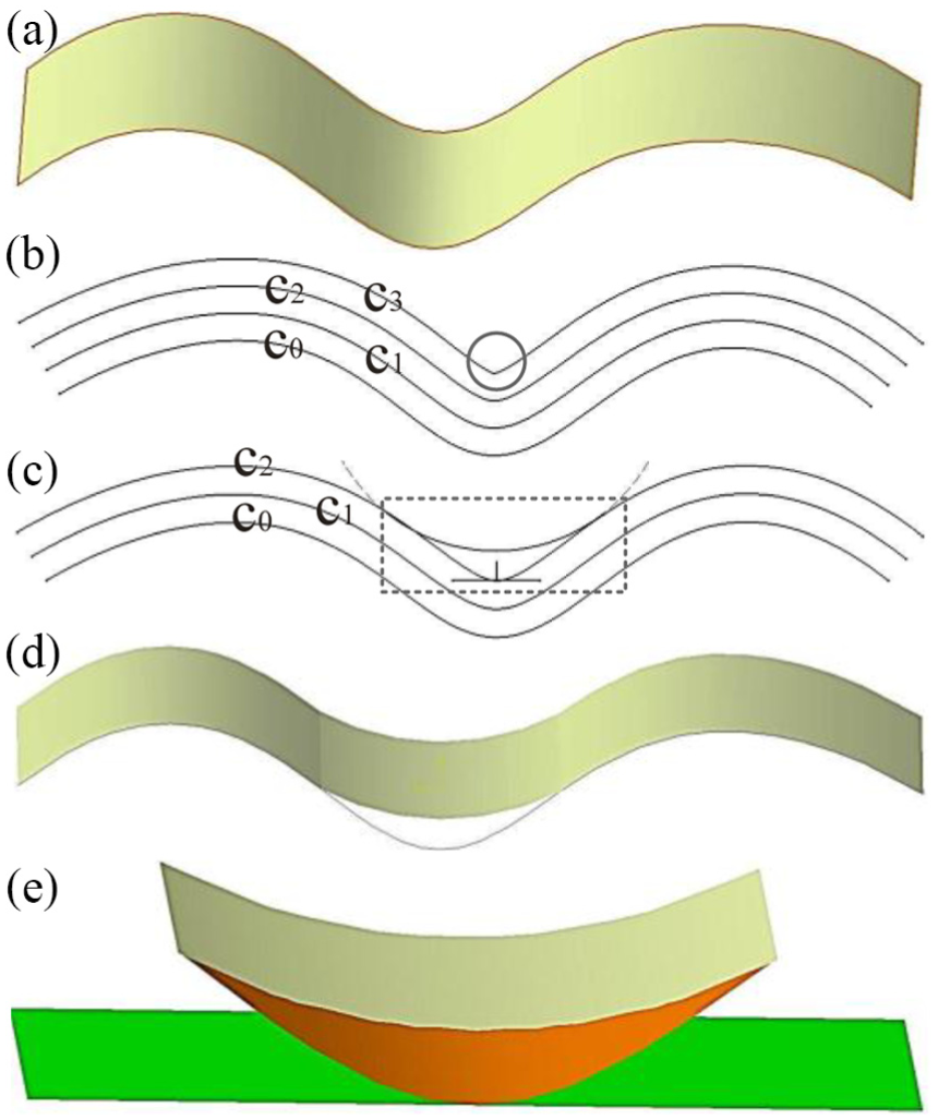
Modification of offset surface: (a) a stretched surface, (b) offset curves of the sketch curve, (c) modification of sketch curve, (d) modified surface, and (e) a new feature.
To solve the problem discussed above, the surface needs to be modified before it becomes deteriorated. An arc tangential to both sides of the valley curve is designed to substitute for the segment of the curve under the arc, as shown in Figure 9(c), and the result of the modified surface is shown in Figure 9(d). As for the domain between the arc curve and the original segment, as shown in Figure 9(e), if it is inside the feature, it is separated into a new feature that belongs to the brep_two5D_feature. For this new feature, the direction of the reference plane is the normal vector of the valley point, as shown in Figure 9(e), and the layer parameter of this feature could be different from the one of the original feature. Obviously, this new feature should be completed before a new layer of the original one is accumulated. To avoid another similar problem arising again, the radius of the arc should be large enough. In this article, the value calculated by the height of the layers is suggested as follows

where
After the offsetting process, there generates a set of surfaces for each freeform feature. For the blade features of the impeller, the reference surface is the hub surface, so the offset results are a set of curved surfaces, as shown in Figure 10(a) and (b). Similarly, the reference surface and offset surfaces of the reentry capsule features are shown in Figure 10(c) and (d).
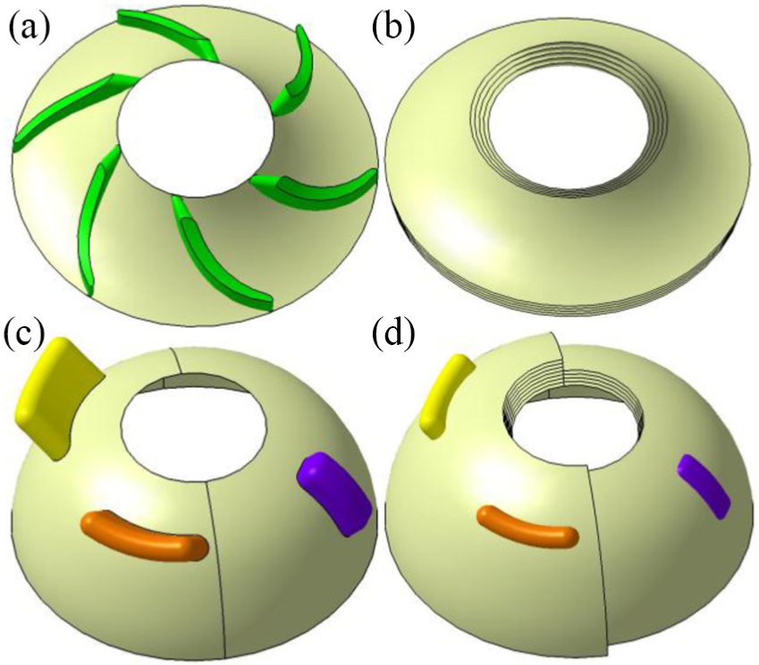
Reference surface and offset surfaces for freeform features of the impeller and the reentry capsule: (a) reference surface of the blade features, (b) offset surfaces of the blade features’ reference surface, (c) reference surfaces of the freeform features of the capsule, and (d) offset surfaces of the reference surfaces of the capsule’s features.
Spatially slice freeform layers
As the AM process develops, the material is accumulated on the offset surfaces. To obtain the exact areas to be built, the spatial slicing should be conducted. In this step, it is necessary to compute the intersections between the offset freeform surfaces and the feature to be built, and the intersection formula is as follows

where
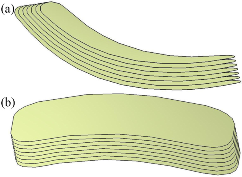
Spatially slicing results: (a) slicing results of one of the impeller’s blade features and (b) slicing results of one of the capsule’s features.
Generate five-axis toolpaths
This is an essential one among all the steps, which will generate the actual toolpaths for the five-axis AM. Since domains of one freeform layer have been figured out, the last step is to generate paths for every domain. Different from the path generation methods of current five-axis AM, the domains to be built are not limited to planar surface, but extend to curved surface. In 2.5-axis AM, there are many path planning modes, such as raster, zig-zag, contour, and so on. Similarly, such modes can be implemented in the five-axis AM path planning on the curved surface, but the distance between the parallel toolpaths should be geodesic distance, namely geodesic offset on the surface. 39 And Figure 12 shows four modes among them. As the curve paths are approximated by a series of segments, similar to the numerical control (NC) machining, there is error in the approximation process. Thus, the toolpath points should be selected along the path curves according to the building tolerance of the feature. To simplify this problem, the iso-parametric strategy is adopted, which has been widely used in NC freeform machining. 40 Currently, the tool direction of the path point is the normal vector to the freeform surface. Moreover, the direction could be constant for the entire layers if needed.
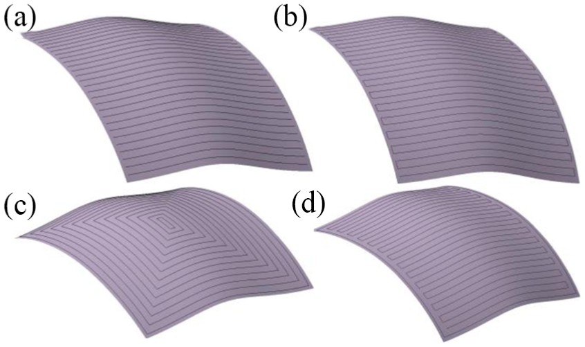
Path modes: (a) raster, (b) zig-zag, (c) contour, and (d) contour–zig-zag.
For the impeller and reentry capsule, the contour mode is used to generate the toolpaths for each layer, as shown in Figure 13. And the whole toolpaths are shown in Figure 14.
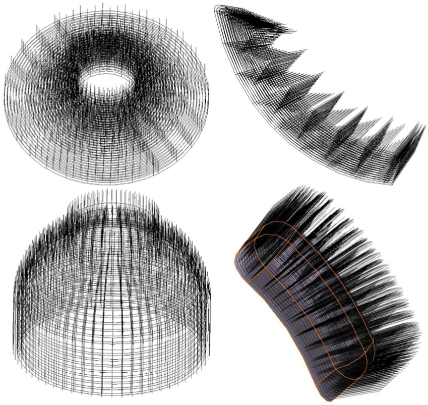
Paths generated for the impeller features and the capsule features.
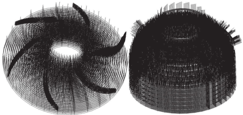
Paths for the impeller and the capsule.
Experiment and discussion
A robotic AM system is constructed to implement the five-axis AM test tasks and to demonstrate the validity of the proposed feature-based path planning method. The printing process is shown in Figure 15(a). The AM features are extracted and recognized through the feature extraction module. The three-axis and real five-axis AM toolpaths for the extracted AM features are obtained by the proposed algorithms in the AM CAM module, which perform as a secondary developed plug-in in the CATIA environment. Then the toolpaths are passed to the simulation module by the .csv file. While in five-axis toolpaths, as there is the only information of the location and the axis direction of a tool, which cannot completely define a posture of a robot tool, a spherical interpolation algorithm realized in MATLAB® is adopted to optimize and convert the five-axis toolpaths with direction vectors to the ones with Euler angles, so that the postures of the robot tool are completely defined. After that, the toolpaths are simulated and programmed by a robot simulation and off-line programming system, and the KUKA robot codes are generated by a robot post-processor. Finally, the tasks are implemented on a hardware system of the robotic fused deposition modelling (robotic FDM).
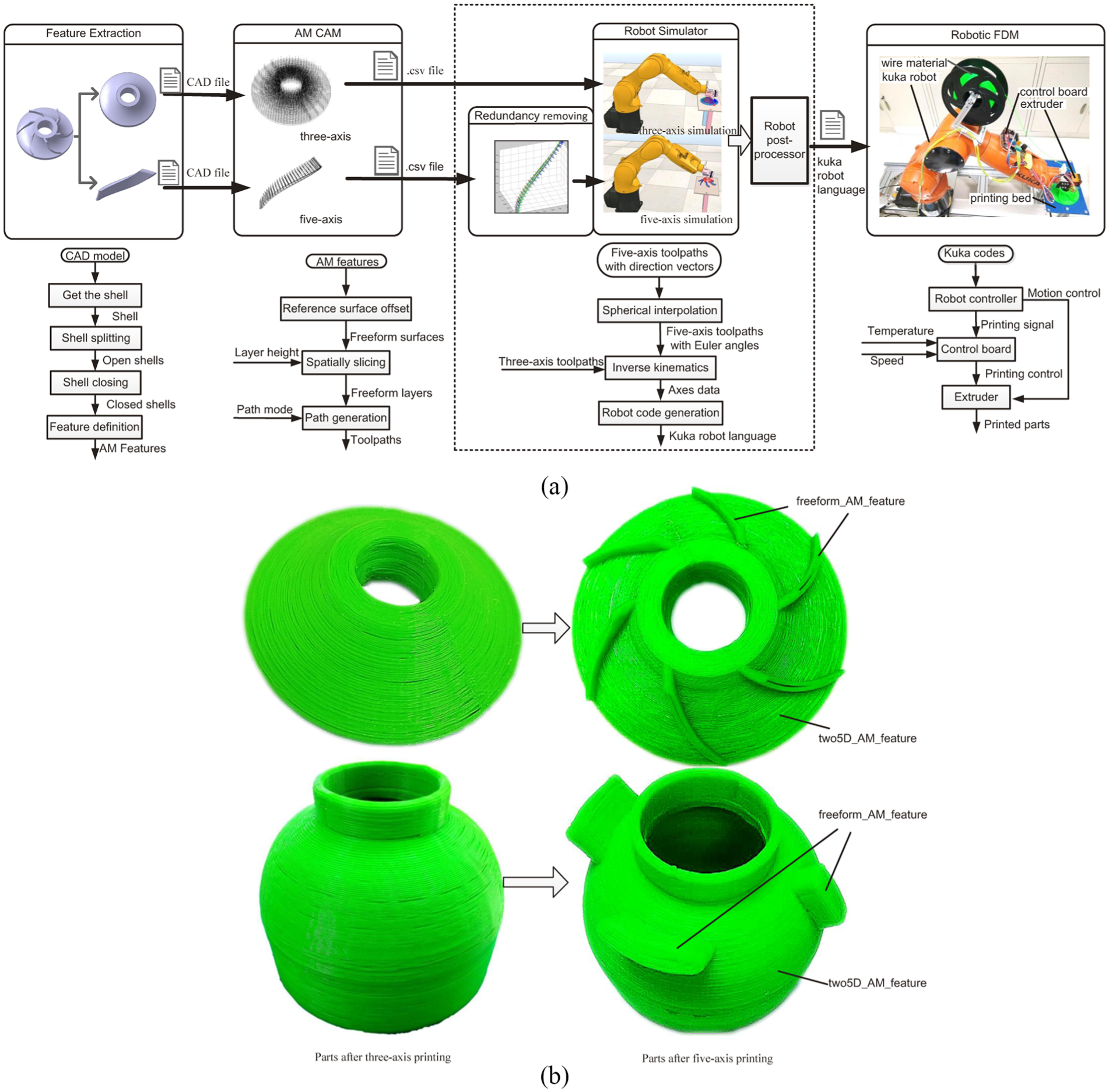
Overview of the feature-based robotic AM process: (a) the printing process and (b) the printed parts.
As shown in Figure 15(a), a KUKA robot (KR6) is used to control the movement of the extruder, attached to the robot flange. An Arduino MEGA 2560 development board and a ramps 1.4 control board, which are commonly used in open-source 3D printing apparatus, play the role of controlling wire feeding and heating input. The polylactic acid (PLA) wire material wheel is placed on the robot and then the parts are printed on a planar platform. The wire (diameter of 1.75 mm) feeding rate is 90 mm/min, and the moving velocity of the extruder is 1200 mm/min.
The impeller and reentry capsule are printed on the robotic FDM platform. With the feature-based path planning methodology, considering the wire feeding rate and printing speed parameters, the paths for the impeller and reentry capsule models are generated, as shown in Figure 14. And the printed parts are shown in Figure 15(b). The two5D features of the two parts are printed first, and then the freeform features are printed on the basis of the two5D ones. From the manufactured results, it is clear that the parts can be printed successfully by the decomposed two5D AM features and freeform AM features. Since the use of the curved layers (lying on the equidistant surfaces of the feature surface), there is less stair-step effect on the surfaces of the freeform AM features. Besides, the overhang features (feature2, feature3, and feature4 of the reentry capsule) are printed without support structures. The results demonstrate the validity of the proposed method that the five-axis curved-layer slicing can reduce support structures and improve surface quality.
In order to further demonstrate the advantages of the proposed method, a fan is printed, as shown in Figure 16. Similarly to the impeller, the fan consists of a hub feature and three blade features. The hub feature is printed first, and then the blade features are printed on the printed hub feature. Obviously, due to the proposed five-axis curved-layer printing method and the flexible motion of the robot, the overhang structures (blades) can be printed successfully without support structures which are indispensable in traditional 2.5D AM. In particular, as shown in Figure 16, two of the three blades are printed with a different material from that of the hub feature, proving that a part can be built with different materials via the proposed feature-based path planning method. In addition, from the sketch map of traditional planar slicing and the proposed curved-layer slicing with the same layer thickness, as shown in Figure 17, it is obvious that the proposed method improves the surface quality by reducing the stair-step effect.
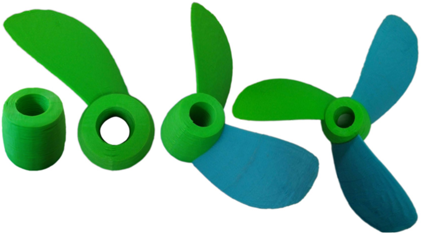
The printing procedure of a fan.
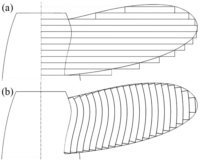
Comparison between planar slicing and curved slicing of a fan blade: (a) planar slicing and (b) curved slicing.
It will be interesting to compare the accuracy of part geometry obtained with the proposed method with classical AM using STL language and with the ideal shape. However, in practice, it is hard to compare the accuracy from the point view of model representation. Firstly, a STL model is an approximation of the ideal shape with a predefined tolerance. Different tolerances cause different coarseness of the model, as shown in Figure 18(a), and the tolerance is totally customized. Second, a STEP file uses analytic models to represent an ideal model with no theoretical error and tolerance definition, as shown in Figure 18(b). The final model accuracy mainly depends on the tessellation accuracy of a specific CAx system rather than the STEP file itself. Thus, there exists no common criterion to compare the accuracy of parts built with STL and STEP.
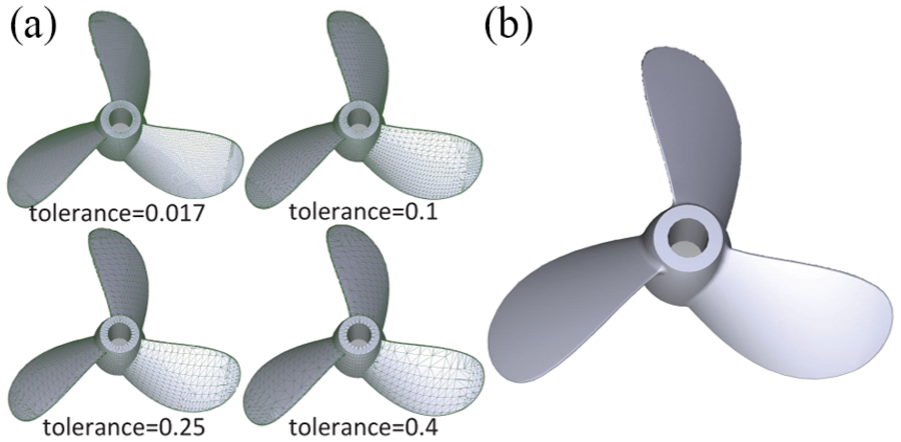
Model of a fan: (a) STL models with different tolerances and (b) STEP model.
It is clearly that to build these freeform features, both the feature-based planning algorithm (generate the five-axis toolpaths) and the robotic AM system (perform the five-axis building tasks) are essential in the experiments. Due to the flexibility of a robot, it is very suitable for a robot to implement the five-axis motion. However, as the robot is just a way to execute the five-axis motion, the toolpaths generated by the proposed algorithm are suitable for other five-axis AM systems by proper post-process.
Conclusion
In this study, the inevitable drawbacks of STL format used in current AM technologies were discussed. To overcome these disadvantages and take the advantages of five-axis strategy, this article introduced a feature-based five-axis path planning method for AM used for the part in STEP format. As the key factors in the feature-based AM, the AM features were defined and categorized into two5D AM feature and freeform AM feature. To extract and recognize the AM features, an automatic feature extraction method is presented. For the stretch_feature and loft_feature, two subtypes of two5D AM feature, the use of CSG modeling parameters is suggested to obtain the contour of a given layer, which can get more accurate results. Furthermore, for the freeform AM feature, a five-axis path planning method was proposed and split into three stages: (1) offset the reference surface, (2) spatially slice the freeform layers, and (3) generate the toolpaths for each freeform layer. The proposed path planning algorithm was tested through experimental results of three models with a robotic FDM system. The results validate the feasibility of the feature-based five-axis path planning method that extends the AM technology to accumulate freeform layers, not limited to planar domains. Still, more efforts should be made to improve the quality of the part manufactured by the feature-based path planning method for AM.
The proposed shell splitting algorithm used in the AM feature extraction is applicable to the case that the genus of the shell is zero. If the genus is greater than zero, the shell splitting could be failed. It is our future research interest to study the method of effectively extracting AM features from a shell that the genus is not equal to zero. In addition, this article mainly focuses on the slicing method which is based on B-Rep representation, but it is also meaningful to employ the feature-based method CSG represented models in the future work.
Footnotes
Declaration of conflicting interests
The author(s) declared no potential conflicts of interest with respect to the research, authorship and/or publication of this article.
Funding
The author(s) disclosed receipt of the following financial support for the research, authorship, and/or publication of this article: This work was supported by the Beijing Municipal Project of Science and Technology (No. Z1611000015 16005).