
Abstract
Laser drilling is a well-established manufacturing process utilised to produce holes in various aeroengine components. This research presents an experimental investigation on the effects of laser drilling process parameters on productivity (material removal rate), hole quality (hole taper) and drilling cost. Single-pulse drilling was employed to drill a thin-walled Inconel 718 superalloy plate of 1 mm thickness using pulsed Nd:YAG laser. The experiments were designed using Box-Behnken statistical approach to investigate the impacts of pulse energy, pulse duration, gas pressure and gas flow rate on the selected responses. Multi-objective optimisation was performed using response surface methodology (RSM) based grey rational analysis (GRA) to identify optimal drilling conditions aiming to maximise the MRR and minimise hole taper and drilling cost. The optimal combination of drilling parameters was found as pulse energy of 20 J, pulse duration of 6 ms, gas pressure of 100 psi and gas flow rate of 40 mm3/s. A detailed cost analysis identified labour cost, gas consumption and machine costs as the major cost elements of the laser drilling process.
Introduction
Lucrative properties of Inconel 718 (IN 718) have made it the best candidate material for the aerospace industry owing to its high strength, wear and fatigue resistance at elevated temperatures. A significant application involves the use of IN 718 in aeroengine components used in high-temperature applications. The operating temperature of these components ranges between 400 and 1100°C. 1 Substantial cooling is necessary to increase the operational life of these components. Therefore, a large number of holes are produced, which serve as a passage for the air coolant in hot path components. In the last few decades, an increase in the number of cooling holes in turbine design has been observed to improve the performance and efficiency of aeroengine. For instance, 40,000 holes are drilled in the afterburner of a gas turbine. 2 However, this material is difficult to manufacture using conventional machining processes because of higher tool wear and low material removal rate. 3
Laser drilling has been extensively adopted for producing cooling holes for aerospace gas turbine components, such as combustion chambers, high-pressure turbine blades and nozzle guide vanes. 4 It is a non-contact and high-speed drilling process used for the manufacture of small and precise holes in almost any material, such as metals, alloys, ceramics and composites. In the laser drilling process, a high power laser beam is directed on the workpiece surface, where the optical energy of the laser beam is thermalised and rapidly heats the base material. Some of the energy is lost due to scattering and reflection of the laser beam. Depending on laser intensity, the material is removed in both the liquid and/or vapour state. Plasma and recoil pressure normally appear in laser drilling due to the high intensities used in the process 5 which help in the expulsion of molten metal and result in the formation of a hole cavity (Figure 1(a)). Assist gas is also used to remove the melt and/or vapours from the hole, as shown in Figure 1(b). The assist gas pressure together with the plasma and recoil pressure control material ejection in the laser drilling process.6,7
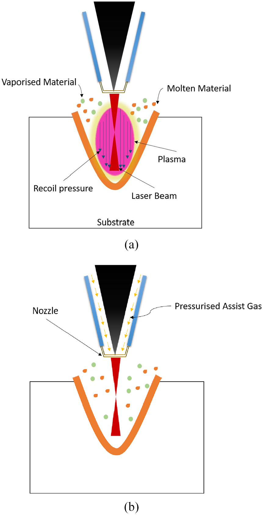
Schematic of the laser drilling process: (a) vapour driven melt expulsion and (b) assist gas melt expulsion.
Different types of laser drilling techniques are available to perform the drilling operation. Gautam and Pandey 8 classified these techniques into static and dynamic drilling based on relative movement between the work part and the laser beam. Single-shot/single-pulse laser drilling and percussion drilling are examples of static drilling where the removal of material is carried out by the effect of several pulses with both the laser beam and the work part in a stable condition. On the other hand, in dynamic drilling, the hole is initially pierced into the centre of the substrate with a laser beam followed by beam rotation towards the circumference of the hole. Trepanning and helical drilling fall into this category. Single-pulse drilling produces holes using only one shot and is the fastest method to drill holes in a material. With single-pulse drilling, drilling time can be reduced but at the expense of hole quality; on the other hand, trepanning gives good hole quality but the drilling time is higher. This shows that there is a trade-off between the quality and drilling time.
The laser drilling process is associated with some undesirable defects, such as micro-cracks, heat affected zone, hole taper, spatter and recast layer that needs to be minimised. 9 Taper formation is an inherent characteristic of laser material processing. It is an essential attribute that significantly influences the drilled hole quality. Zero or lower hole taper is always desirable specifically in aeroengine components where close tolerances and high quality are strict requirements. 10 Hole taper is affected by several factors, such as laser beam characteristics, types of drilling methods applied and laser processing parameters. 11 The characteristics of a laser beam depend upon the laser optic or hardware components used to deliver the laser beam from the laser source to the workpiece. These components include mirrors, beam splitters, fibres, collimators, focus heads etc. Special optics are needed to achieve holes with a minimum taper angle, which is out of the scope of this study. The laser processing parameters which affect hole taper include laser pulse duration/width, pulse energy, assist gas pressure, beam focal position and gas flow rate.12–20 In previous research studies, several authors have explored the effects of these process parameters for single-pulse drilling. Yilbas and Yilbas 21 used the full factorial method to evaluate the impacts of focal position and material thickness on the quality of laser-drilled holes in Nimonic 75. In another study, Yilbas 22 examined the effects of pulse duration, pulse energy, workpiece thickness and focal length on hole quality by comparing different materials (titanium, nickel and stainless steel). All process parameters were found to affect hole quality significantly. Sarfraz et al. 15 evaluated the influence of process parameters (pulse duration and pulse energy) on hole taper during laser drilling of IN 718 alloy. The results revealed that hole taper is significantly influenced by pulse duration and pulse energy. Variations in hole diameter were investigated by Rodden et al. 23 during laser drilling of carbon fibre composites. The exit hole diameter was found to be a function of material thickness and pulse energy. Yilbas and Aleem 24 examined the impacts of single-pulse laser drilling on the hole quality in Tantalum. The selected parameters were pulse energy, assist gas pressure, lens focal position and workpiece thickness. It was observed that all applied parameters significantly influence hole quality. The impact of peak power and pulse duration on hole taper was studied by Kacar et al. 25 A significant influence was observed on hole taper with an increase in peak power and pulse duration. Xiao et al. 26 and Zhang et al. 27 investigated the influence of various process parameters on hole taper and the heat-affected zone, and recast layer respectively. It was revealed that hole quality could be enhanced when proper selection and control of process parameters is applied.
Productivity is also an important feature of the manufacturing process besides hole quality. The parameters which affect productivity include pulse width, gas pressure, gas flow rate and pulse energy.19,28–30 Panda et al. 19 examined the impact of the laser drilling process parameters, including pulse duration, gas pressure, number of pulses, and gas flow rate on the material removal rate and hole quality. It has been shown that variation in the process parameters significantly affects MRR and hole quality. Priyadarshini et al.30,31 extended this work to optimise the hole quality and MRR using grey-fuzzy and fuzzy-TOPSIS methods. The influence of pulse energy and pulse duration on hole quality and material removal rate was examined by Sarfraz et al. 15 The results revealed that both productivity and hole quality is greatly influenced by the control of applied parameters.
Cost is a key factor being considered in every industry and has a significant impact on product outcomes because of the global competitive market. Various researchers have estimated the operating cost associated with different laser machining processes. Benyounis et al. 32 and Eltawahni et al. 33 estimated the operating costs of laser welding and laser cutting along with the product quality. The authors used Response Surface Methodology (RSM) to investigate the impact of process parameters and find out the optimal combination of process parameters at minimum cost and maximum quality. A significant influence of process parameters was observed on both the operating cost and quality. Recently, Sarfraz et al. 34 reported that the process parameters affecting the performance of the laser drilling process also have a substantial impact on the cost that needs to be investigated.
A holistic literature review shows that the productivity and the product quality of laser drilling have had little attention from researchers. However, there is no research work available discussing the cost of the laser drilling process. This research contributes to an evaluation of the influence of the laser drilling process parameters improving the material removal rate and hole quality while minimising the drilling cost. A comprehensive statistical analysis has been performed to evaluate the effects of the process parameters. Empirical models have been developed successfully to predict output responses. The adequacy of developed models has been verified through analysis of variance (ANOVA). Furthermore, multi-objective optimisation has been applied to achieve the best combination of laser drilling parameters for optimum response values. A detailed cost analysis has also been performed to explore the economic implications of the laser drilling process.
Materials, equipment and methods
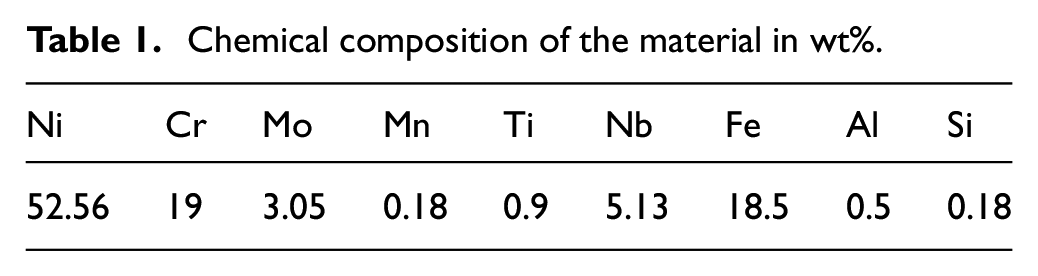
The samples of IN 718 plates of 100 mm × 100 mm × 1.0 mm dimensions were procured from Goodfellow, UK. The chemical composition of the material was validated via optical emission spectroscopy, the results of which are provided in Table 1.
Chemical composition of the material in wt%.
The drilling operation was performed using a flash lamp-pumped Nd:YAG laser (JK300HPS model, JK Lasers, UK). Laser system specifications are presented in Appendix 1. All experiments were conducted at a laser beam incidence angle of 90° to the material surface. The focal position of the laser beam was maintained at the workpiece surface using a 300 mm focal length lens, giving a spot diameter of 0.9 mm. The laser beam profile distribution was Gaussian with TEM00. Conical nozzle with a diameter of 2.0 mm was used to deliver the assist gas, and the distance between the nozzle tip and the substrate was fixed at 3.0 mm. Compressed air was employed as an assist gas. Gas pressure and gas flow rate were controlled through a gas regulator and gas flow meter installed on the cylinder. The experimental setup and its schematic diagram are presented in Figure 2.
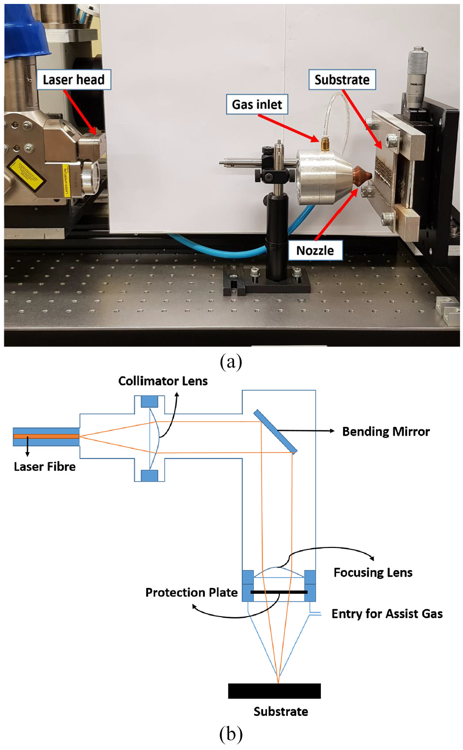
Laser drilling setup: (a) experimental and (b) schematic.
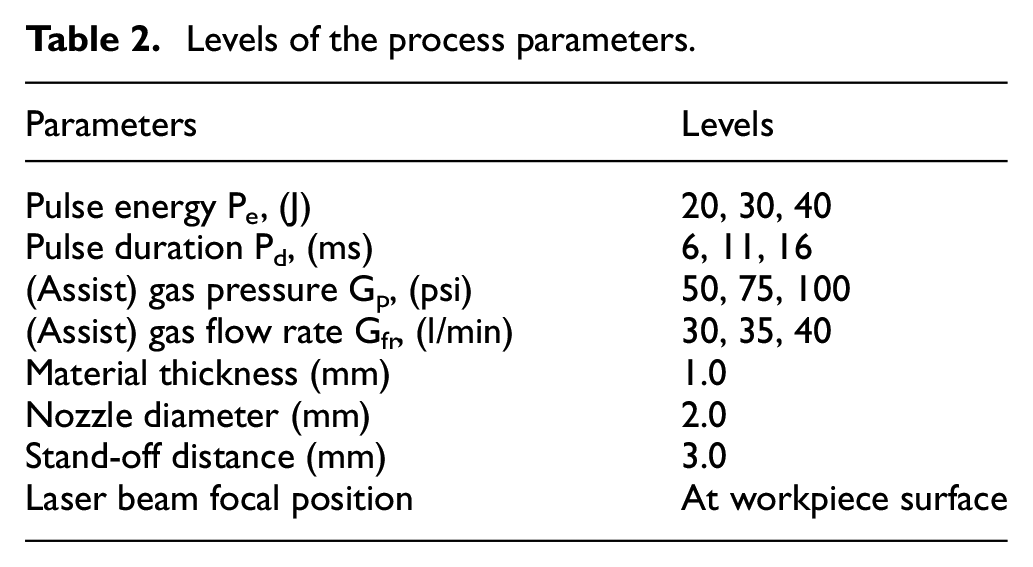
In order to analyse the influence of the process parameters on the material removal rate (MRR), drilling cost (Cd), and hole quality (HT), response surface methodology was employed. Four laser drilling process parameters were selected, namely pulse energy, pulse duration, gas pressure and gas flow rate. These process parameters were chosen based on their influence on material removal rate, hole quality and drilling cost.12,14,15,19,28–30,34 The selection of limits and their levels was based on trial experiments and literature review. Table 2 shows the controlled parameters along with the selected levels. Some of the parameters were kept constant and are also provided in Table 2.
Levels of the process parameters.
A series of experiments was performed using the Box-Behnken experimental design technique. Overall 27 experiments were conducted with four process parameters and three centre points. 35 Each experimental run was replicated three times to assure the reproducibility and reliability of the experimental procedure. Figure 3 shows a photograph of the different experiments conducted; both the entry and exit sides of drilled holes are presented, where each row represents the repetition of experiments. The experimental runs with the observed response values are provided in Table 3. A similar strategy was adopted to calculate the hole taper and material removal rate, as reported in previous work. 15 The detailed cost analysis is explained in the following section.
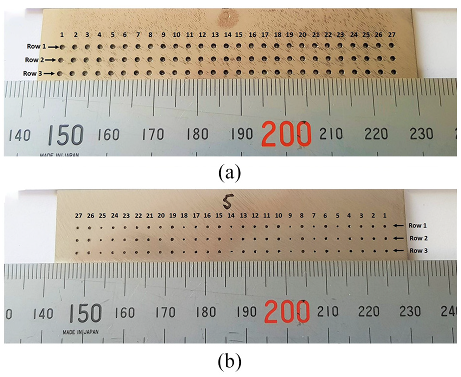
Arrays of holes after drilling: (a) entry side and (b) exit side.
Experimental layout and results.
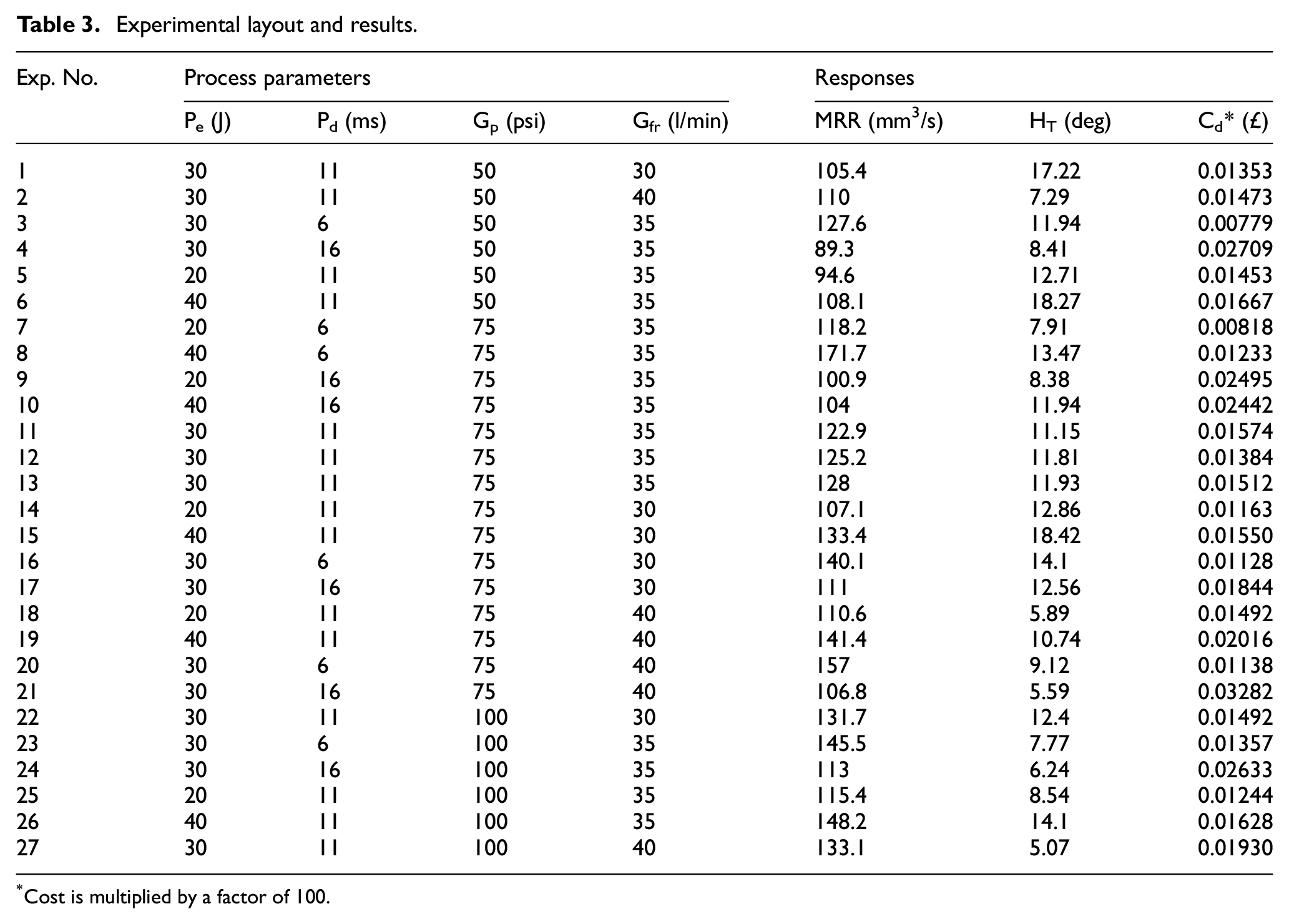
Cost is multiplied by a factor of 100.
Cost estimation
Manufacturing cost estimation is an essential activity for companies targeting to become successful in the current competitive scenario. For this purpose, this research intends to provide a detailed cost analysis for the laser drilling process considering single-pulse laser drilling.
In order to highlight substantial cost components, material cost, labour cost, maintenance cost and equipment running cost are considered. The total cost is changed with a small modification to a single cost driver. Therefore, it is only possible to generate a comprehensive cost estimate for a particular process when all of its cost drivers are identified. 36
The main cost drivers relevant to the laser drilling process have been determined through experts’ opinion and literature review (see Appendix 2). Equipment running cost, maintenance, material and labour costs are the key drivers in laser drilling cost estimation. After a comprehensive study, it was identified that equipment running cost further includes equipment depreciation, electricity consumption, components replacement, gas consumption, component handling and overhead costs. When all cost drivers are finalised, a cost is allocated to each driver and the total process cost can be calculated.
Laser drilling cost estimation
The total cost of laser drilling per hole (

Labour cost
Labour cost per hole (
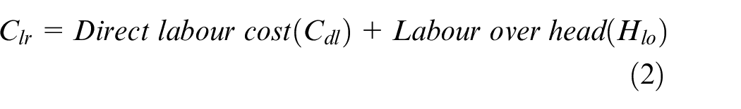
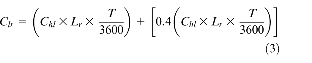
where
Machine cost
Machine cost per hole includes the machine depreciation cost (
The machine cost (
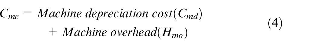
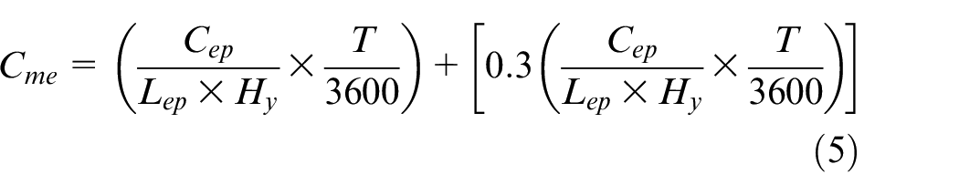
where
Cost of electricity
Electricity cost comprises energy consumed by the equipment, the unit price of energy and the drilling time. Four factors were taken into consideration for the electrical energy consumption of equipment that is, electrical power of the chiller, electrical power of the laser, utilised laser power and the maximum power achieved by the laser. The cost of electricity (
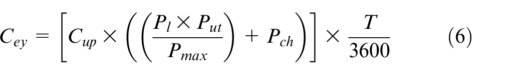
where
Cost of gas consumption
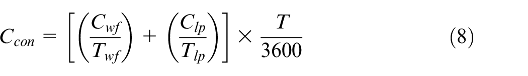
The cost of gas consumption per hole (
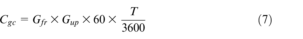
where
Cost of consumables
Consumable laser components (water filters, laser pumps) have a limited lifetime and need regular replacement. The consumables cost per hole (
where
Cost of maintenance
Pulsed Nd:YAG laser requires periodic maintenance and service. Therefore, maintenance cost depends on the hourly cost of maintenance labour, maintenance time required, available working time of machine and drilling time per hole, as shown in equation (9).
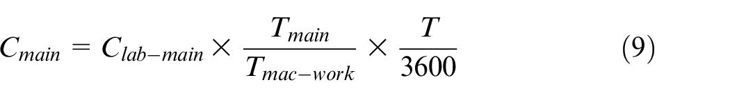
where
Total drilling cost
Labour cost
The percentage contribution of all cost components under low, medium and high levels of process parameters is provided in Figure 4. At the low level of parameters, labour cost was a maximum of 62% followed by gas consumption cost of 21%, machine cost of 10%, maintenance cost of 4%, electricity cost of 2% and consumable cost of 1% in the total drilling cost respectively (Figure 4(a)). A similar contribution of cost components was observed at medium and high levels of process parameters (Figure 4(b) and (c)). For the laser cutting process, Riveiro et al. 39 reported similar findings that showed gas consumption, machine (laser/chiller) cost and electricity cost as major cost components ignoring the labour cost.
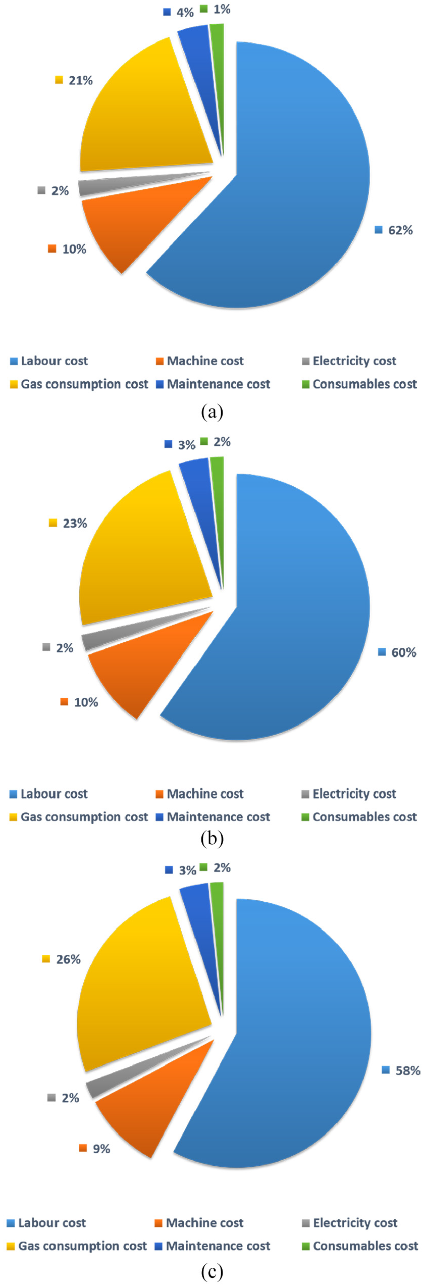
Percentage contribution of cost components in the total drilling cost at (a) low level: Pe = 20 J, Pd = 6 ms, Gp = 50 psi, Gfr = 30 mm3/s (b) medium level: Pe = 30 J, Pd = 11 ms, Gp = 75 psi, Gfr = 35 mm3/s and (c) high level: Pe = 40 J, Pd = 16 ms, Gp = 100 psi, Gfr = 40 mm3/s of process parameters.
Results and discussion
Mathematical modelling
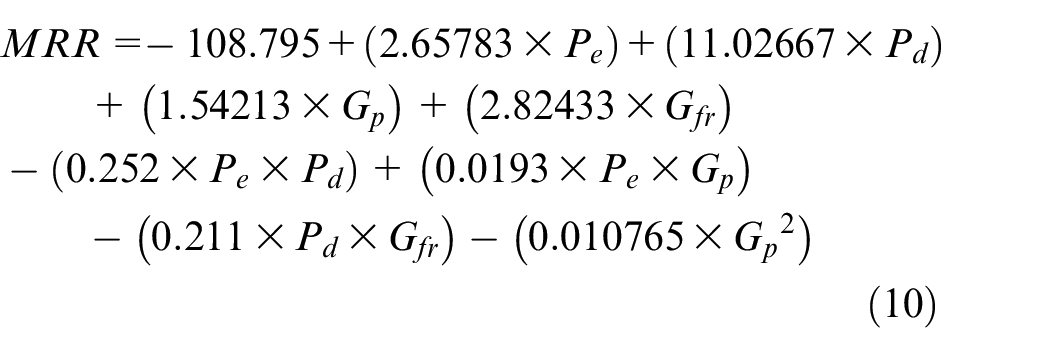
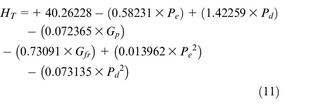
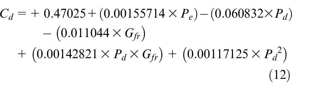
Regression analysis was applied using Design Expert® (v10) to develop mathematical models for predicting output responses. The obtained mathematical models for MRR, hole taper and drilling cost are provided in equations (10) to (12), respectively.
The significance of process parameters and the developed mathematical models was confirmed through analysis of variance (ANOVA). The analysis results are provided in Appendix 3. These results show essential terms (with p values < 0.05) and the adequacy measures (R2 and adjusted R2). All process parameters were found as significant for MRR and hole taper; however, in the case of drilling cost three process parameters that is, pulse energy, pulse duration and gas flow rate were found to be the most contributing parameters. It is noted that the values of adequacy measures are close to 1, which provides proof of the adequacy of the developed models.
Investigation
To examine the individual and simultaneous influence of input process parameters, that is, pulse energy, pulse duration, gas pressure and gas flow rate on MRR, hole quality and drilling cost, 3D surface plots were drawn and are provided below.
Influence of pulse energy and pulse duration on MRR
Figure 5 illustrates the effects of pulse energy and pulse duration on MRR. It is observed that MRR is more sensitive to a change in pulse duration as compared to pulse energy. Furthermore, MRR increases with increase in pulse energy. This is due to the fact that high pulse energy increases the melt surface temperature, which in turn enhances recoil pressure. This ultimately results in high MRR. On the other hand, higher MRR is observed at low values of pulse duration because peak power of the laser beam is higher when a short pulse duration is employed, which helps in penetration during the laser drilling operation and results in an increase in the material removal rate. Similar results are noted by Yang et al. 40 and Sarfraz et al. 15
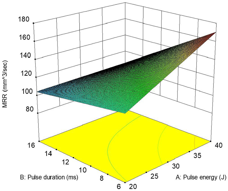
Surface plot for MRR: Pe versus Pd.
Influence of gas pressure and gas flow rate on MRR
The surface plot of MRR (Figure 6) based on gas pressure and gas flow rate shows that MRR is maximum at high level of gas flow rate. Because higher gas flow rate provides additional thermal energy to support the heating phenomena due to the oxidising nature of compressed air. MRR is found increasing with increase in gas pressure, because higher the pressure greater the kinetic force of gas that efficiently expels the molten material outside the hole cavity. Pattanayak and Panda 41 and Panda et al. 19 reported the similar results. It is also evident that MRR is more influenced by gas pressure than the gas flow rate.
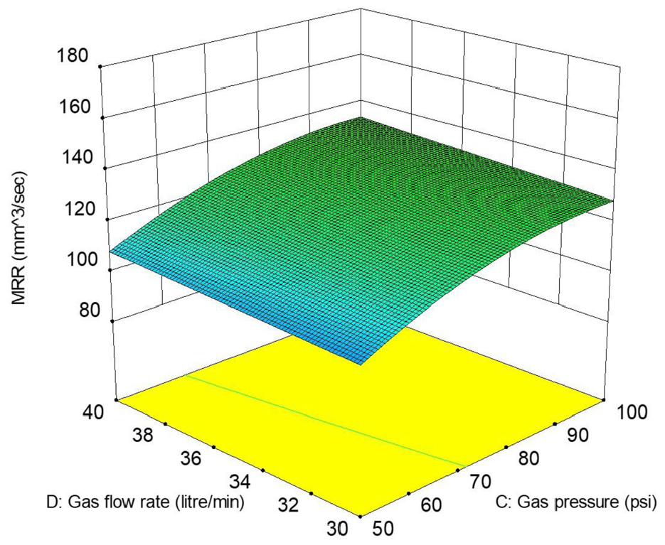
Surface plot for MRR: Gp versus Gfr.
Influence of pulse energy and pulse duration on hole taper
The relationship between the effects of pulse energy and pulse duration on hole taper is illustrated in Figure 7. There is a noticeable increase in hole taper with an increase in pulse duration up to a specific limit. Further, hole taper starts to decrease at higher levels of pulse duration because of sufficient laser beam-work piece interaction time. On the other hand, maximum hole taper is obtained at high values of pulse energy. This is because a high pulse energy laser beam melts and vaporizes the material (top) surface instantly that creates a large (entrance) hole diameter. The intensity of the laser beam decreases due to diffraction as it penetrates, which increases the hole taper. Similar findings have been observed by Sarfraz et al. 15 and Chatterjee et al. 42
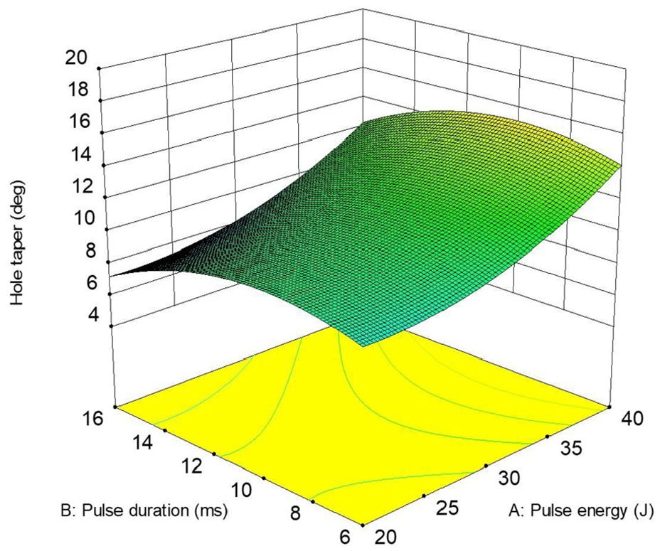
Surface plot for hole taper: Pe versus Pd.
Influence of gas pressure and gas flow rate on hole taper
The effects of gas pressure and gas flow rate on hole taper are revealed in Figure 8. Hole taper decreases with increase in gas pressure. This is because higher gas pressure properly removes the molten metal from the material (top) surface. Moreover, an increase in pressure does not permit the molten metal to set down inside the hole cavity. Thus, hole taper reduces when higher gas pressure is used which is in accordance with the findings of Chatterjee et al. 42 A similar trend has been observed with the increase in gas flow rate because higher compressed air flow rate increases the localised temperature due to its combustible supportability and results in efficient removal of the material from the hole exits which results in lower hole taper, as stated by Nawaz et al. 20
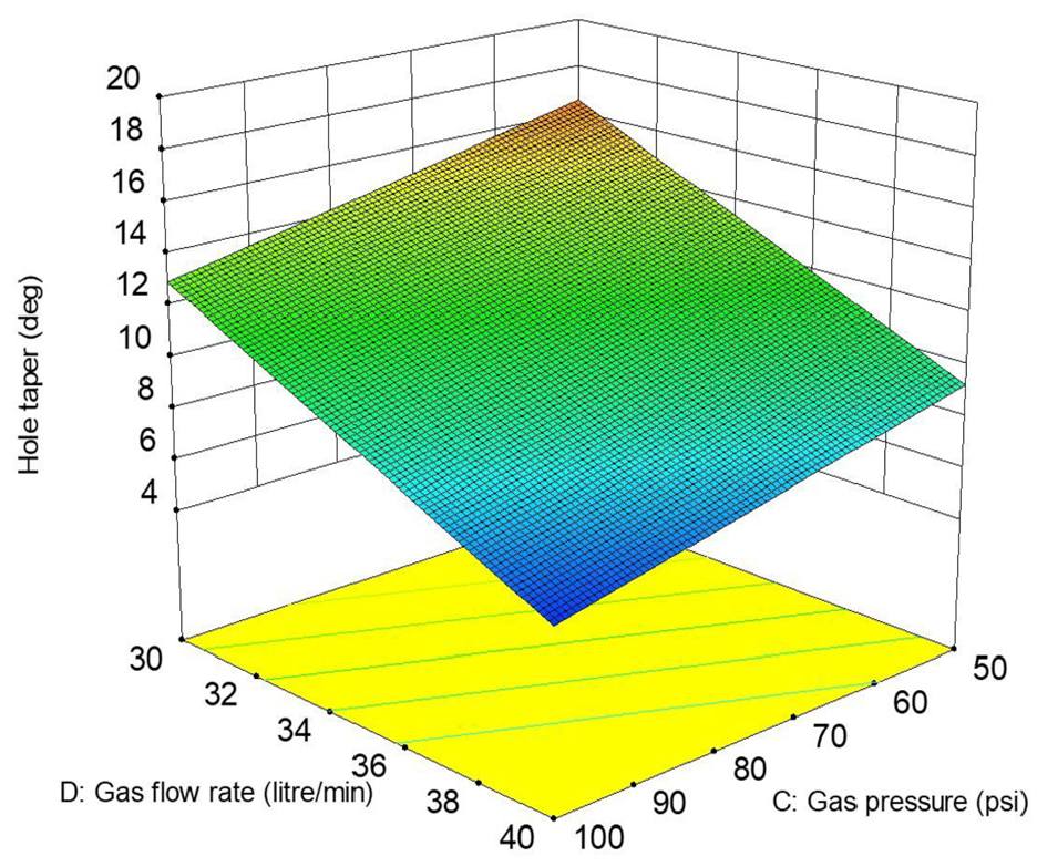
Surface plot for hole taper: Gp versus Gfr.
Influence of pulse energy and pulse duration on drilling cost
Figure 9 illustrates the response of pulse energy and pulse duration on drilling costs. The lowest value of drilling cost is observed at minimum values of pulse duration and pulse energy. This increase in drilling cost at higher pulse duration and pulse energy values results from an increase in drilling time and power consumption respectively. 33 The response graph also indicates that pulse duration has more influence than pulse energy.
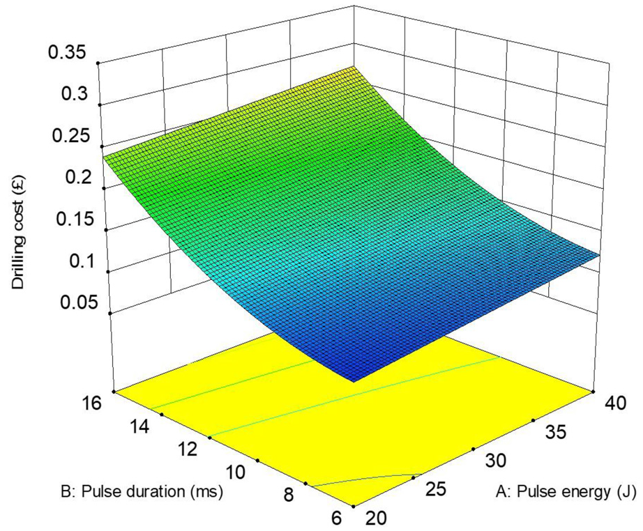
Surface plot for drilling cost: Pe versus Pd.
Influence of gas pressure and gas flow rate on drilling cost
The effects of gas pressure and gas flow rate on drilling costs are described in Figure 10. An increase in gas flow rate shows a noticeable increase in drilling cost, whereas no prominent effect is observed from gas pressure. Higher gas flow rate results in more gas consumption, which ultimately increases drilling cost. Riveiro et al. 39 and Eltawahni et al. 33 noticed the same results for the CO2 laser cutting process.
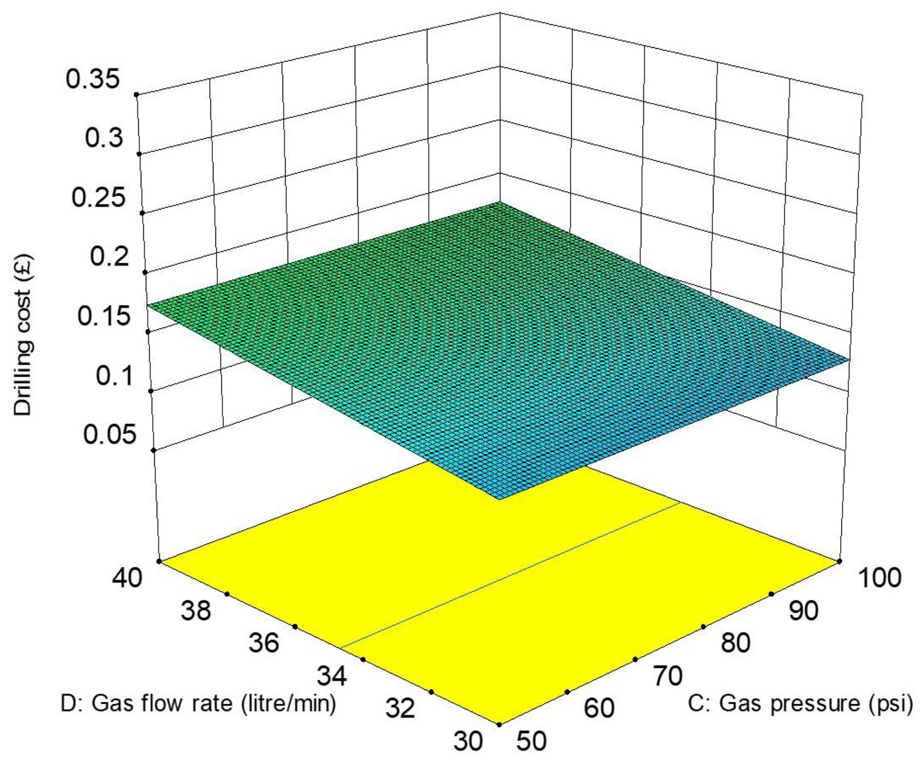
Surface plot for drilling cost: Gp versus Gfr.
Optimisation
Different methods and techniques are available to solve single-response optimisation. However, these procedures cannot be used when multiple responses are involved and the optimal combination of process parameters is desired. Generally, in multi-responses, the response parameters are conflicting; for instance, lower hole taper is achieved with high pulse duration and high gas flow rate but increase in pulse duration and gas flow rate affect the cost. To mitigate these problems, RSM based Grey rational analysis (GRA) was used to perform multi-objective optimisation aiming to maximise the MRR while minimising hole taper and drilling cost. In GRA, the first step is “grey relational generating,” where normalisation is carried-out on the collected responses to develop the range between 0 and 1. According to the desired target for the responses, such as MRR (maximisation in target), cost and hole taper (minimisation in target) relations are defined. For MRR, “larger-the-better” is the desirable target, so the following relation (equation (13)) is used:
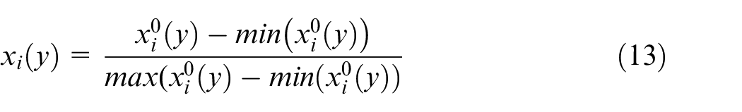
Here,
However, “smaller-the-better” is the desired target for cost and hole taper. That is why the desired target is defined in the following relation (equation (14)):
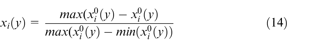
Here,
In the second step, grey relational coefficients (GRC) are determined to develop a relationship between real experimental normalised values and the desirable data. The grey-relational coefficient is defined by equation (15):
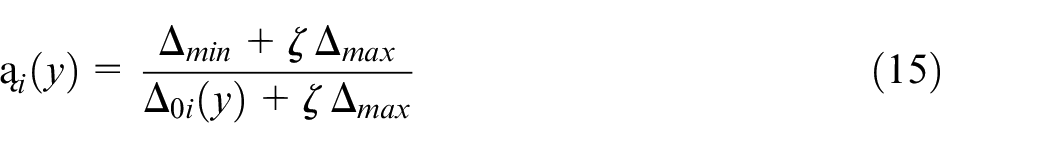
Here,
The grey-relational-grade (GRG) is determined as the weighted sum of GRC. Finally, GRG is calculated using equation (16).
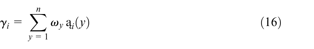
Here
Based on the conflicting responses, grey relation entropy method 44 was used to assign the weights to each response to avoid human-made assumptions. In this way, a realistic weight calculation method is used systematically. This method assigns weight based on the influence of process parameters on the response, where higher weight is allocated to the response with a higher variation.
Firstly, the mean value of GRC was calculated at each level of the process parameter associated with the individual response (Table 4). For example, at level 1 of pulse energy, the mean value of GRC for MRR was determined as 0.394. The maximum and minimum values of the mean of GRC were then used to calculate the range, as shown in equation (17).
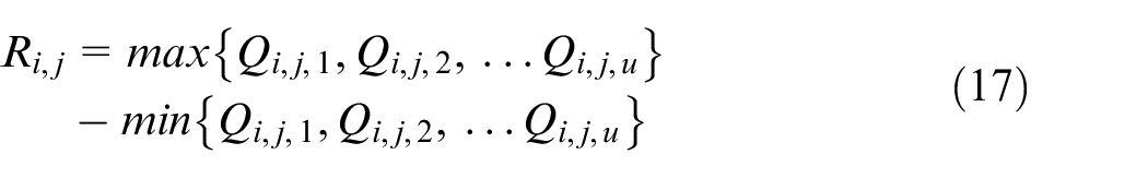
Weight assignment using the grey relation entropy method.
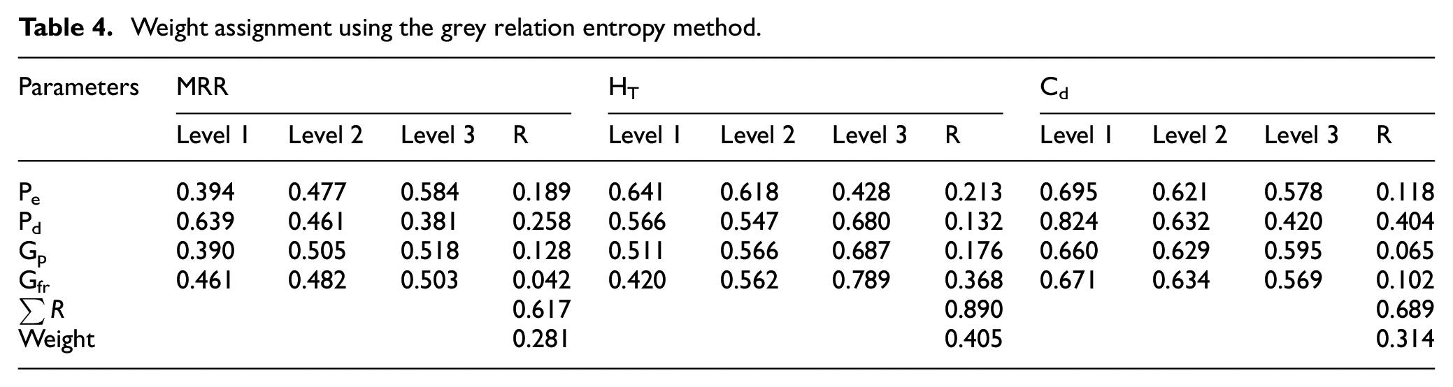
where
The value of weight
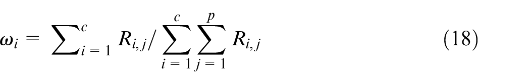
Where
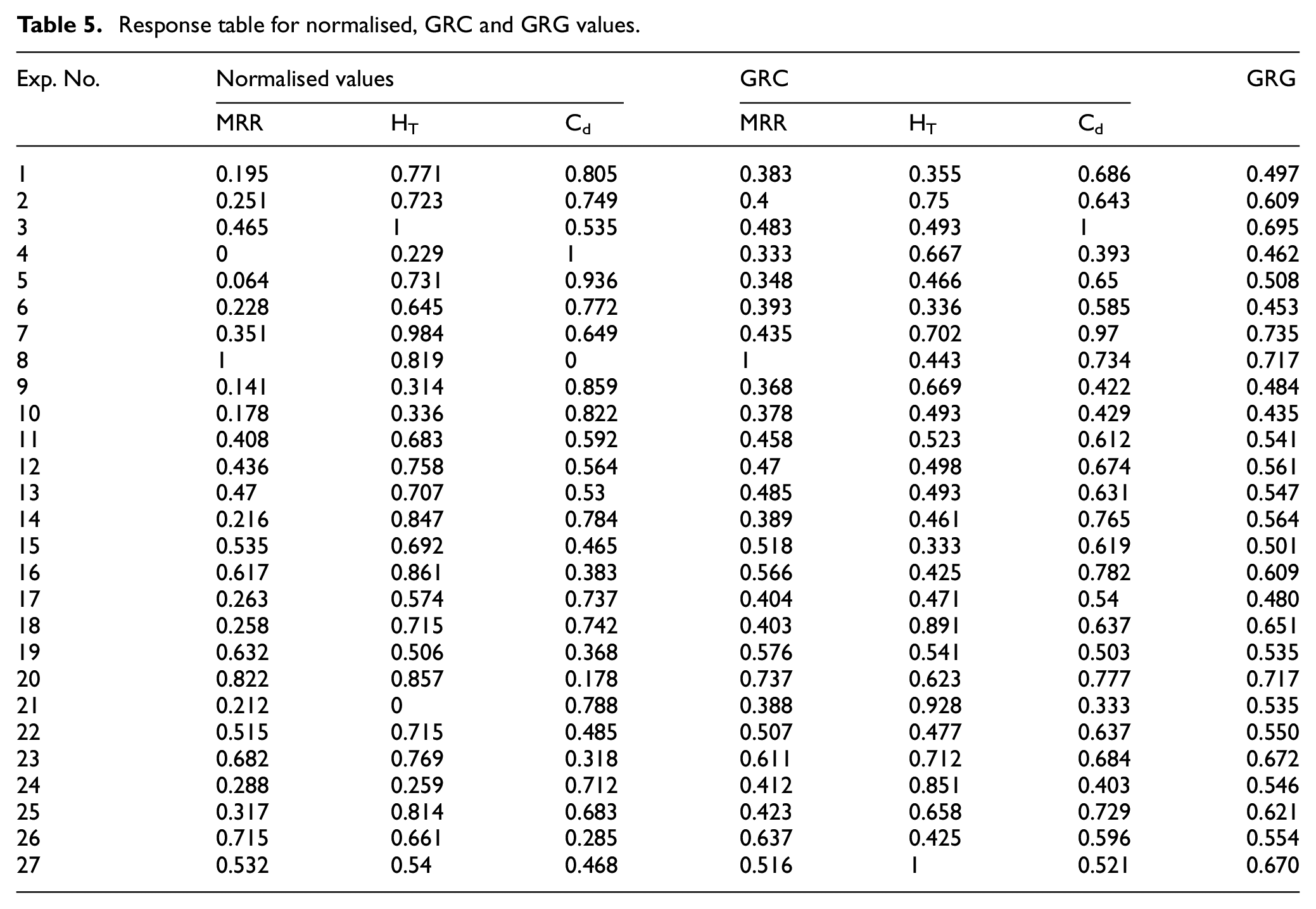
Table 5 depicts the normalised, grey relational coefficients and grey relational grade values for the corresponding responses. It is evident that test no. 7 depicts the highest value of GRG. Therefore, the seventh experiment gives the optimum condition for higher MRR with lower hole taper and cost.
Response table for normalised, GRC and GRG values.
Further, the mean value of GRG was also calculated for each level of the drilling parameter and is provided in Table 6. Moreover, the total mean of GRG for all experiments is calculated as 0.572 (Table 6). Each row presents the process parameter and its levels. The level of the corresponding process parameter with the highest value of GRG is presented in bold form (Table 6). For instance, 0.594 is the highest value of GRG for pulse energy. Therefore, the optimum parameter levels for higher MRR and lower hole taper and cost are Pe1-Pd1-Gp3-Gfr3.
GRG response table at each level of process parameters.
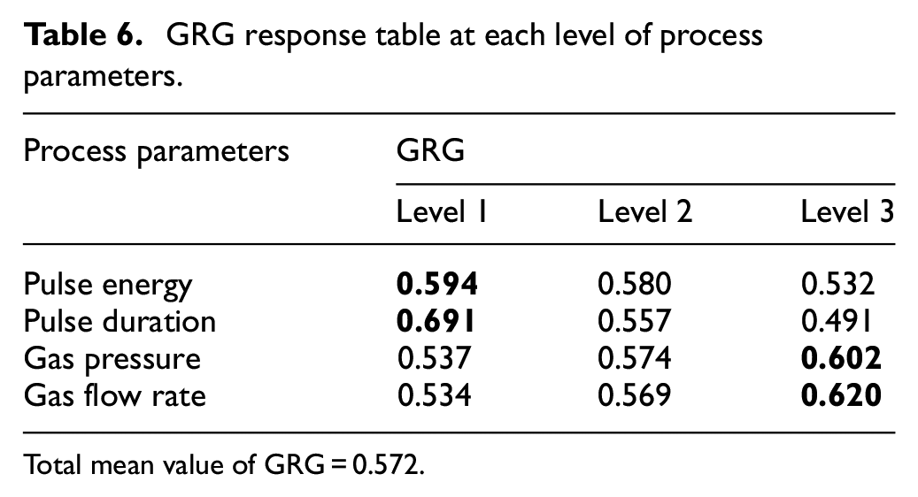
Total mean value of GRG = 0.572.
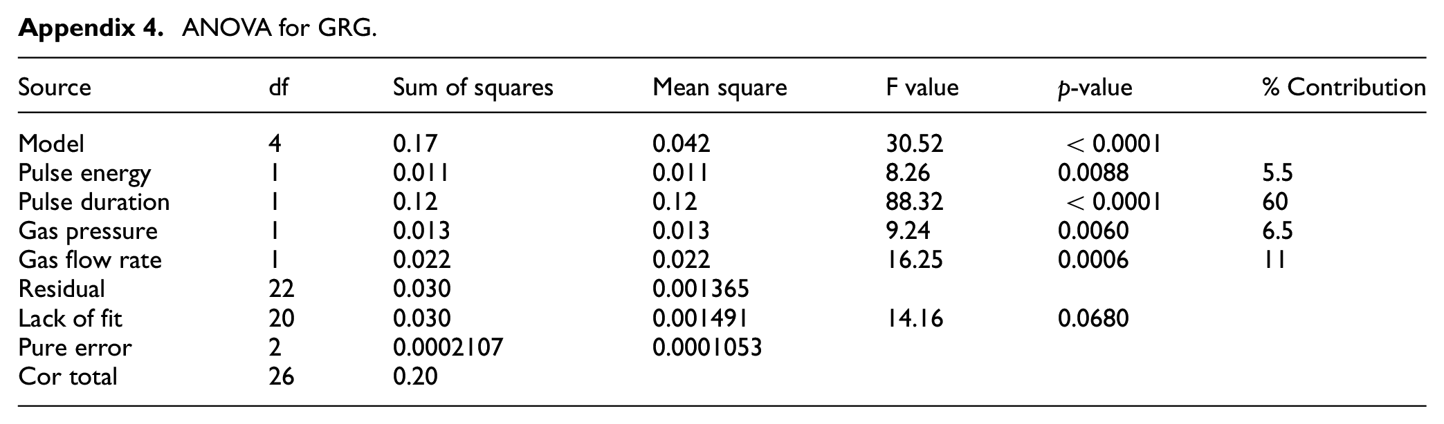
The ANOVA was performed for GRG to evaluate the significance of each process parameter. The results are provided in Appendix 4. The percentage contribution of each process parameter in GRG was also computed. Pulse duration was found as the most significant parameter with a 60% contribution that affects the MRR, hole taper, and cost followed by gas flow rate (11%), gas pressure (6.5%) and pulse energy (5.5%).
Confirmatory test
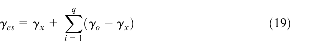
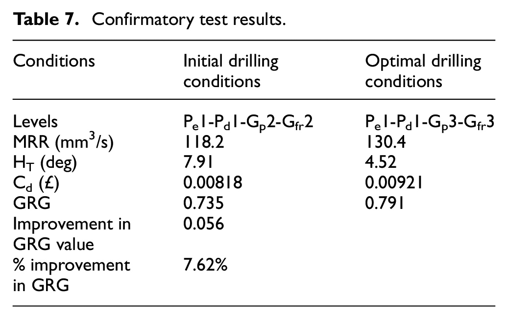
A confirmation test has been done for verification of improvement in the responses. The levels of process parameters selected for the confirmation test are shown in Table 7. The initial drilling conditions represent test No. 7 (optimum parameters from Table 5) and the optimal drilling conditions represent the optimum parameter levels from Table 6. The estimated value of GRG for optimal drilling condition (
Confirmatory test results.
where
Conclusions
In the present study experimental analysis of productivity, quality and process cost is highlighted for the single-pulse laser drilling of IN 718 superalloy. The impacts of pulse energy, pulse duration, gas pressure and gas flow rate have been examined on the selected responses. Multi-objective optimisation was performed using RSM based grey rational analysis (GRA) to get the optimal combination of process parameters against the optimised response values (maximum MRR with minimum hole taper and drilling cost). In addition, detailed cost analysis has been performed to explore the economic implications of the laser drilling process. Based on the experimentation results and analysis, the main observations are listed below:
The results of ANOVA for responses revealed all the selected process parameters as significant concerning MRR and hole taper. However, for drilling cost, pulse duration was determined to be the most effective parameter followed by gas flow rate and pulse energy.
For best results, low pulse energy should be used with short pulse duration since high pulse duration decreases the productivity and excessive pulse energy increases the hole taper. Also, both pulse energy and pulse duration affect the cost. On the other hand, higher gas pressure and gas flow rate can be employed to minimise the hole taper and increase productivity for only a small increase in cost. In this study, the most optimum drilling conditions identified were pulse energy of 20 J, pulse duration of 6 ms, the gas pressure of 100 psi and gas flow rate of 40 mm3/s.
The ANOVA results for GRG depict the highest percentage contribution of pulse duration (60%) among all the process parameters. This shows that pulse duration contributed significantly during single-pulse drilling operation when the simultaneous optimisation of all responses is considered.
Analytical cost modelling provides the economic perspective for laser drilling. The detailed cost analysis revealed labour cost, gas consumption and machine costs as the major cost elements of the laser drilling process.
The process parameters (pulse energy, pulse duration, gas pressure, and gas flow rate) were formulated with respect to the responses (MRR, hole taper, and cost) to develop mathematical models using regression analysis. The values of adequacy measures (R2 and adjusted R2) depict that the developed mathematical models are adequate and can be used to predict the output responses for the proposed drilling parameters range.
One quality attribute of the laser drilling process (hole taper) has been considered in this work. The surface integrity of laser-drilled holes can be analysed along with other response variables, such as heat-affected zone, recast layer thickness, surface roughness and circularity to improve drilling performance. Other heuristics techniques, such as NSGA-II, Artificial Bee Colony and Particle Swarm Optimisation can also be used for the analysis. Moreover, other process parameters, including nozzle diameter, nozzle stand-off distance and laser beam focal position can be considered along with different materials.
Further research is in progress to explore the economic prospects of other laser drilling processes, that is, percussion and trepanning drilling.
Footnotes
Appendix
ANOVA for GRG.
| Source | df | Sum of squares | Mean square | F value | p-value | % Contribution |
|---|---|---|---|---|---|---|
| Model | 4 | 0.17 | 0.042 | 30.52 | <0.0001 | |
| Pulse energy | 1 | 0.011 | 0.011 | 8.26 | 0.0088 | 5.5 |
| Pulse duration | 1 | 0.12 | 0.12 | 88.32 | <0.0001 | 60 |
| Gas pressure | 1 | 0.013 | 0.013 | 9.24 | 0.0060 | 6.5 |
| Gas flow rate | 1 | 0.022 | 0.022 | 16.25 | 0.0006 | 11 |
| Residual | 22 | 0.030 | 0.001365 | |||
| Lack of fit | 20 | 0.030 | 0.001491 | 14.16 | 0.0680 | |
| Pure error | 2 | 0.0002107 | 0.0001053 | |||
| Cor total | 26 | 0.20 |
Acknowledgements
The authors want to thank the Punjab Educational Endowment Fund (PEEF, Pakistan) and Cranfield University (United Kingdom) for financial support of this research. The authors are also thankful to Mr Masood Habib Ahmed for proofreading this manuscript.
Declaration of conflicting interests
The author(s) declared no potential conflicts of interest with respect to the research, authorship, and/or publication of this article.
Funding
The author(s) received no financial support for the research, authorship, and/or publication of this article.