
Abstract
This study investigates the effects of electro-discharge parameters on the surface integrity in small-hole drilling. Discharge current, pulse on-time and pulse off-time were chosen as variable parameters. The gap voltage, dielectric flushing pressure, electrode rotation, electrode polarity and capacitance were taken as constant. Material removal rate, surface roughness, average white layer thickness, overcut and taper were taken as outputs for this study. Experiments were performed on DIN 1.2080 (X210Cr12) cold working tool steel, and ∅2 mm single-hole brass electrodes were used. The experimental results indicate that a compromise solution is required in selection of the electrical discharge machining parameters (i.e. discharge current, pulse on-time and pulse off-time) to maintain machining stability (melting–evaporation and removal of debris). As the stability is maintained during the process, dimensional accuracy increases and a better finish can be obtained with a reasonable machining time.
Keywords
Introduction
Hole drilling is one of the basic metalworking processes; about 40% of all production time is spent to produce holes. Drilling process of small hole (∅0.3–∅6.0 mm), which has the large depth to diameter ratio, is very difficult by using traditional methods. Especially workpiece material, which has greater strength and hardness like carbide, tool steel and super alloys, is impossible to drill. Small-hole electrical discharge machining (EDM) drilling process is a highly economic method for drilling fast and highly precise holes into all types of conductive materials, whether hard or soft. The process is used for fuel injectors, venting holes of injection moulds, coolant holes of injection cutting tools, hardened punch ejector holes, wire-EDM starter holes, holes in turbine blades and other similar operations.
However, there are some irregularity on surface and dimension of the EDMed hole depending on non-linearity of electrical parameters. In EDM process, abnormal discharge currents cause high electrode wear. 1 Moving of debris from narrow gap by dielectric fluid is difficult, and it limits depth of the hole. 2 Increase in debris results in easier breakdown of dielectric fluid and so causes extra arc pulses. Instability of these pulses even though less than 5% causes more serious effect on the hole quality in drilling EDM process. 3 Moreover, removal of debris causes taper hole, and the wear of electrode causes enlargement of diameter of the hole. Manufacturing of high-precision tools and dies requires the closer tolerances; however, overcut and taper are the main problems with regard to geometrical exactness and quality of the hole. During the small-hole EDM drilling process, all of melted material cannot be removed, some of them re-solidifies and creates a recast layer also known as white layer. There are large number of micro-cracks and pores on the surface of this layer, which cause residual stress and affect the surface quality.
Researchers investigated the effect of many input variables on the output performances. Wang and Yan 4 reported that the effect of electrical parameters is more significant than the effect of the other parameters on blind hole drilling of Al composite. Singh et al. 5 studied the effect of machining parameters over output performances of ram EDM of Al-SiC composite and reported that material removal rate (MRR), taper, radial overcut and surface roughness increase while the current and pulse on-time settings were higher. Leao et al. 6 evaluated dielectric liquid and electrode materials for optimization of hole drilling process. Kuppan et al. 7 reported that duty factor, discharge current and electrode rotation affect MRR, whereas pulse on-time and discharge current influence the surface roughness. In small-hole EDM drilling, the effects of non-electrical parameters on MRR were researched by Cao et al. 8 Ekmekci et al. 9 studied the effects of pulse energy on geometry and surface damage of the blind holes machined by micro-EDM. Pradhan et al. 10 examined the effects of different process parameters on the surface topography and white layer in micro-EDM. Bozdana et al. 11 studied the effect of different electrode material on small-hole EDM drilling performance parameters. Yilmaz and Okka 12 researched the influence of number of channels in the electrodes on performances of small-hole EDM drilling process. They reported that the single-channel electrode is better than the multi-channel electrode to obtain higher MRR; however, the surface roughness is better when using multi-channel electrode. Ponappa et al. 13 studied the influences of EDM parameters on hole quality and observed that servo speed and pulse on-time are mainly affecting surface roughness and taper. The change of the bottom and side overcuts, dimensions of electrode, dimensions of the hole and the positioning correctness of machine in the EDM process are studied by Chiang and Wang. 14 Janmanee and Muttamara 15 investigated the influence of EDM parameters on MRR, electrode wear rate (EWR) and tapered hole of martensitic stainless steel AISI 431.
Even though the effect of many input parameters on the output performances of hole drilling by EDM has been investigated, results are mainly dependent on the type of hole (macro, micro, small) and the material. However, the effect of machining parameters on white layer thickness in small-hole EDM of cold work tool steel is not yet available. Also, a comprehensive study which considers MRR, surface roughness, white layer thickness, overcut, taper length and angle all together is required to clarify the influence of machining parameters on the hole surfaces. In this study, the effects of small-hole EDM parameters on the MRR, surface roughness, white layer thickness, overcut, taper length and angle are experimentally investigated on DIN 1.2080 (X210Cr12) cold working tool steel.
Experimental studies
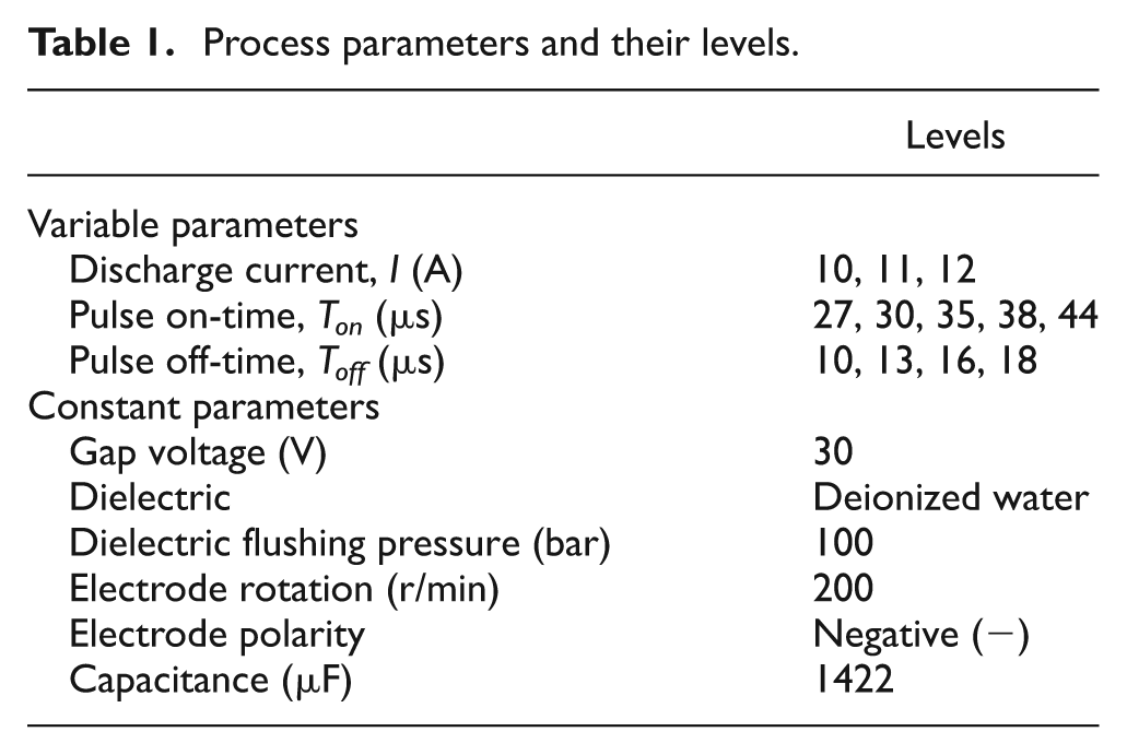
In this study, JS AD-20 hole drilling EDM machine was used to realize experimental studies. Discharge (average) current (I), pulse on-time (Ton) and pulse off-time (Toff) were chosen as variable parameters. The gap voltage, dielectric flushing pressure, electrode rotation, electrode polarity and capacitance were taken as constant parameters (see Table 1).
Process parameters and their levels.
Work material used in this study was DIN 1.2080 (X210Cr12) cold working tool steel. The specimens were prepared as a rectangular block with the dimension of 10 ×10 × 40 mm. The top and bottom faces of the specimens were ground before the experiments. The ground surfaces of the two specimens were mated and then 2-mm-diameter and 10-mm-deep holes were drilled on the interface (Figure 1). ∅2 mm single-hole brass electrodes were used throughout the experiments. Input parameters (discharge current, pulse on-time and pulse off-time) and output parameters (surface roughness, white layer thickness, MRR, overcut taper length and angle) were recorded. Three holes were drilled repeatedly on the same specimen keeping the process parameters constant. The average values of three holes are used for comparisons.
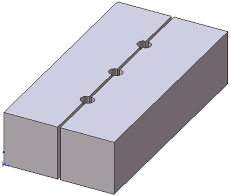
Schematic view of the specimen.
The results of the preliminary tests (see Figure 2) undertaken in this study show that the lower discharge currents (I < 10 A) are not sufficient to evaporate the molten material properly and result in higher machining time, that is, very low MRR (less than 0.06 g/min). Similarly, higher values of discharge currents (I > 12 A) cause very high electrode wear and very rough surfaces (Ra greater than 6 µm) due to larger molten metal crater on the workpiece. Therefore, the experiments were carried out for 10–12 A. The pulse off-time shorter than 10 µs causes secondary spark so that rougher surface and more overcut. However, higher pulse off-time means increasing machining time. For that reason, experiments were performed between 10 and 18 µs pulse off-times.
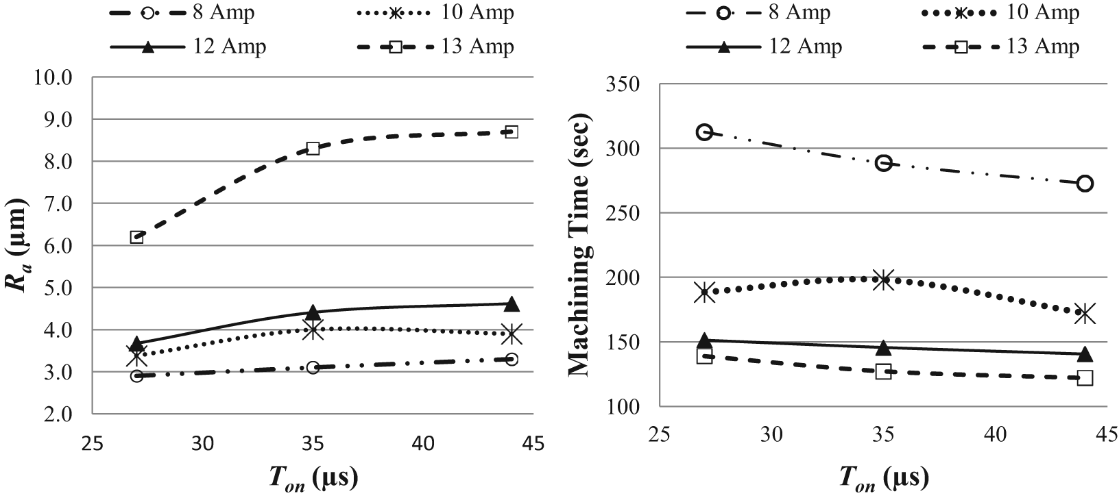
Results of the preliminary tests for Ra and machining time.
Measuring of MRR
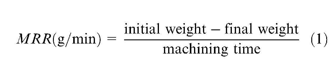
MRR is always a significant phenomenon in the manufacturing process because machining time affects the cost. Therefore, higher MRR can be considered as a main objective of EDM processes. MRR is calculated as the loss of mass of the workpiece material during the machining by dividing the machining time. A digital weighing scale and an electronic timer were used to measure the mass lost and the drilling time, respectively. The following formula is used to determine the MRR value
Measuring of surface roughness
In this study, a Mitutoyo Surftest SJ-401 tester was used to measure surface roughness of drilled holes. The cut-off length and evaluation length were chosen as 0.8 and 4 mm, respectively. The average values were taken from the three repeated holes with two measurements of each.
Measuring of white layer thickness
During the small-hole EDM process, rapid heating and cooling occurs and causes a heat-affected layer on the machined surface. The top of the layer consists of re-solidified layer and recast structure. The recast layer appears white colour in microscope, and thus, it is commonly named as the white layer. The white layer is very hard and brittle and has micro-cracks. This structure increases the surface roughness and decreases the fatigue strength. Therefore, the determination of the white layer thickness and its structure is important to predict the service life of parts machined by hole EDM.
In order to measure white layer thickness of the EDMed specimens, the transverse section of specimens was ground with silicon carbide paper starting from 200 to 600 grit using water as lubricant by using grinder polisher machine. Then, these faces were polished with diamond paste and alumina oxide and etched with 5% nital solution for inspection of specimens by Nikon Ma100 Metallographic Microscope.
Measuring of hole geometry
The dimensional accuracy of the hole is determined by the amount of overcut and taper. The EDMed hole will always be larger than the electrode diameter due to the spark gap and the secondary spark formation during removal of the debris by pressurized liquid.
The overcut is important for determination of the final diameter of the hole. The overcut is measured as the difference between the diameters of the machined hole and the electrode (Figure 3)

where Oc is the overcut, da is the average diameter of the hole after machining and de is the diameter of the electrode. Since the overcut is not uniform along the machined depth, the diameter has been measured from the number of locations along the hole, and average value was calculated as da.
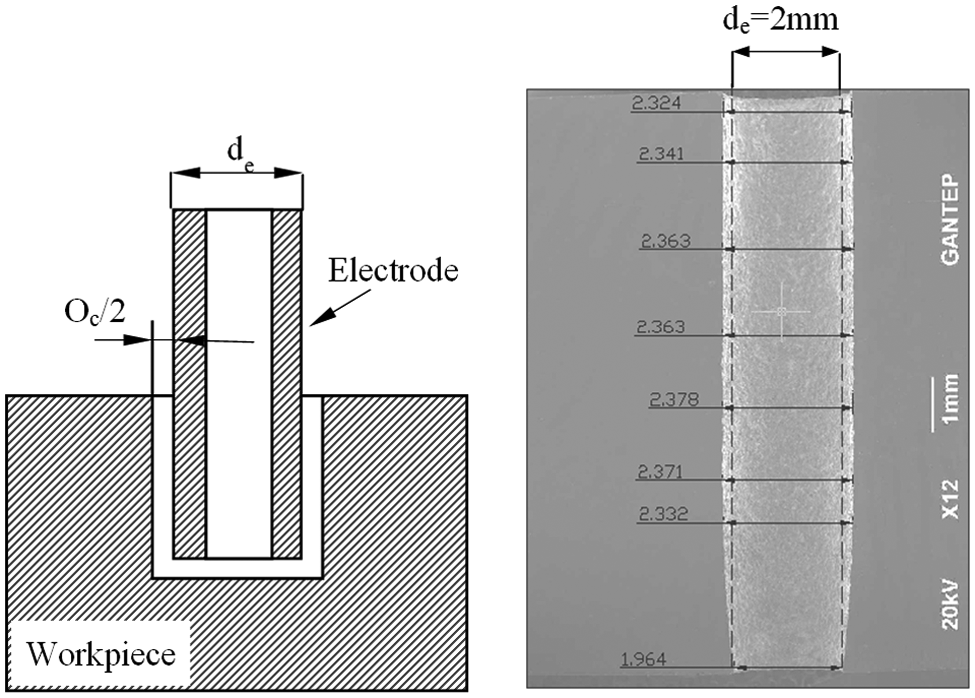
Overcut of a hole.
Taper is the angular measure of the change in the diameter of hole between the opening of the hole and its corresponding end (Figure 4). The main reason of formation of taper is the corner wear of the electrode. The taper angle of the hole is measured as
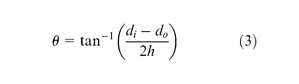
where θ is the taper angle, h is the depth of taper and di and do are the entrance and the exit diameters of the hole, respectively. Scanning electron microscopic (SEM) images of drilled holes were used to measure the overcut and the taper of the small holes.
Taper of hole.
Results and discussion
Effects on MRR
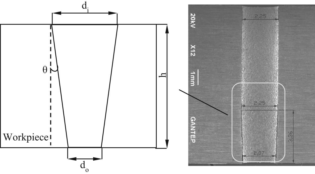
In EDM drilling process, the melt removal causes the crater shape on the machined surface since process of electrical spark erosion took place repeatedly. The total mass of the molten metal concludes the amount of MRR. Generally, when the discharge current increases, MRR also rises. This is clearly observed in Figures 5 and 6. As the discharge current increases, the energy density on the workpiece material also increases; this increases the amount of molten and vaporized metal as well.
Effect of I and Ton on MRR when Toff = 16 and 10 µs.
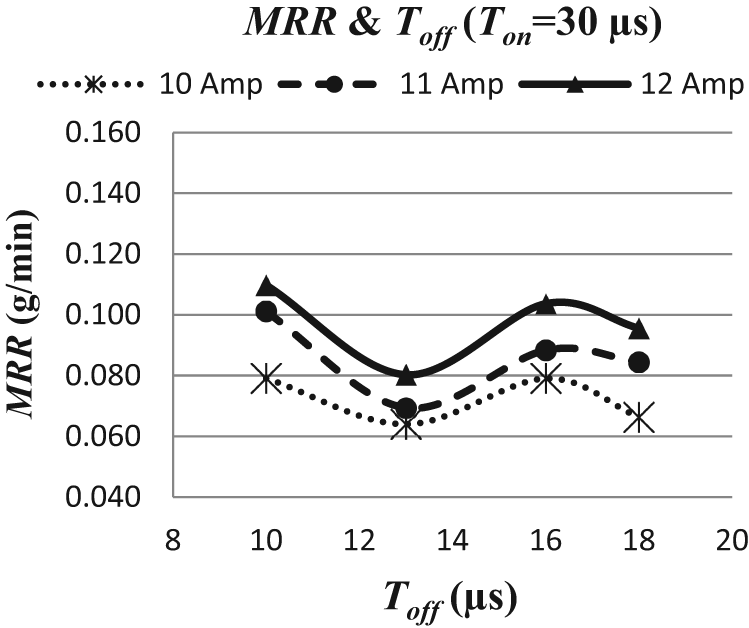
Effect of I and Toff on MRR when Ton = 30 µs.
For all different discharge currents, the changes in MRR with respect to pulse on-time are similar. It can be pointed out from Figure 5 that as the pulse on-time increases, MRR also increases up to a maximum value for a specific optimum Ton. This optimum point changes with pulse off-time, for example, maximum MRR was obtained at Ton = 38 µs when Toff = 16 µs and at Ton = 35 µs when Toff = 10 µs. Beyond this point, MRR starts decreasing. This is due to longer Ton that causes instability, i.e., diminishing pressure and energy of the plasma channel between the molten material and the electrode.
The effect of pulse off-time (Toff) on MRR is shown in Figure 6. The MRR decreases when the Toff is increased. So, the increase in Toff considerably causes an increase in machining time. The Toff time is necessary to stabilize the EDM process at the end of each discharge. In the Toff time, reconstruction of insulation in the working gap occurs. 16 MRR proportionally increases with decreasing Toff time. However, there exists a restriction to decrease the Toff because each discharge needs enough time to deionize dielectric.
This limit value changes based upon the Ton and the discharge current. Throughout machining, Toff is to be set accurately to avoid arcing, which helps to achieve high MRR. Moreover, too short Toff causes lack of time to flush away debris from the gap among electrode and workpiece.
Effects on surface quality
Surface quality is defined with two main factors, which are surface texture and surface integrity. Surface texture is related to geometric irregularities of the solid surface, which is generally described as surface roughness. Surface integrity comprises the metallurgical changes of the surface and surface layer. The exposed discharge energy of EDM process creates very high temperature at the spark point. This melts and vaporizes a minute part of the workpiece, and a crater is formed on the machined surface. Therefore, the surface texture is characterized by these craters, and it is determined by EDM parameters (I, Ton, Toff).
From the SEM images of the holes, three different regions were observed, as shown in Figure 7. At the entrance of the hole, rapid evaporation and melting occurs due to high temperature and intense discharge effect. If the discharge current increases, disintegrations on the surface get larger. The SEM images of the region of the hole for 10 and 12 A are shown in Figure 8. However, this region is very narrow (less than 50 µm).
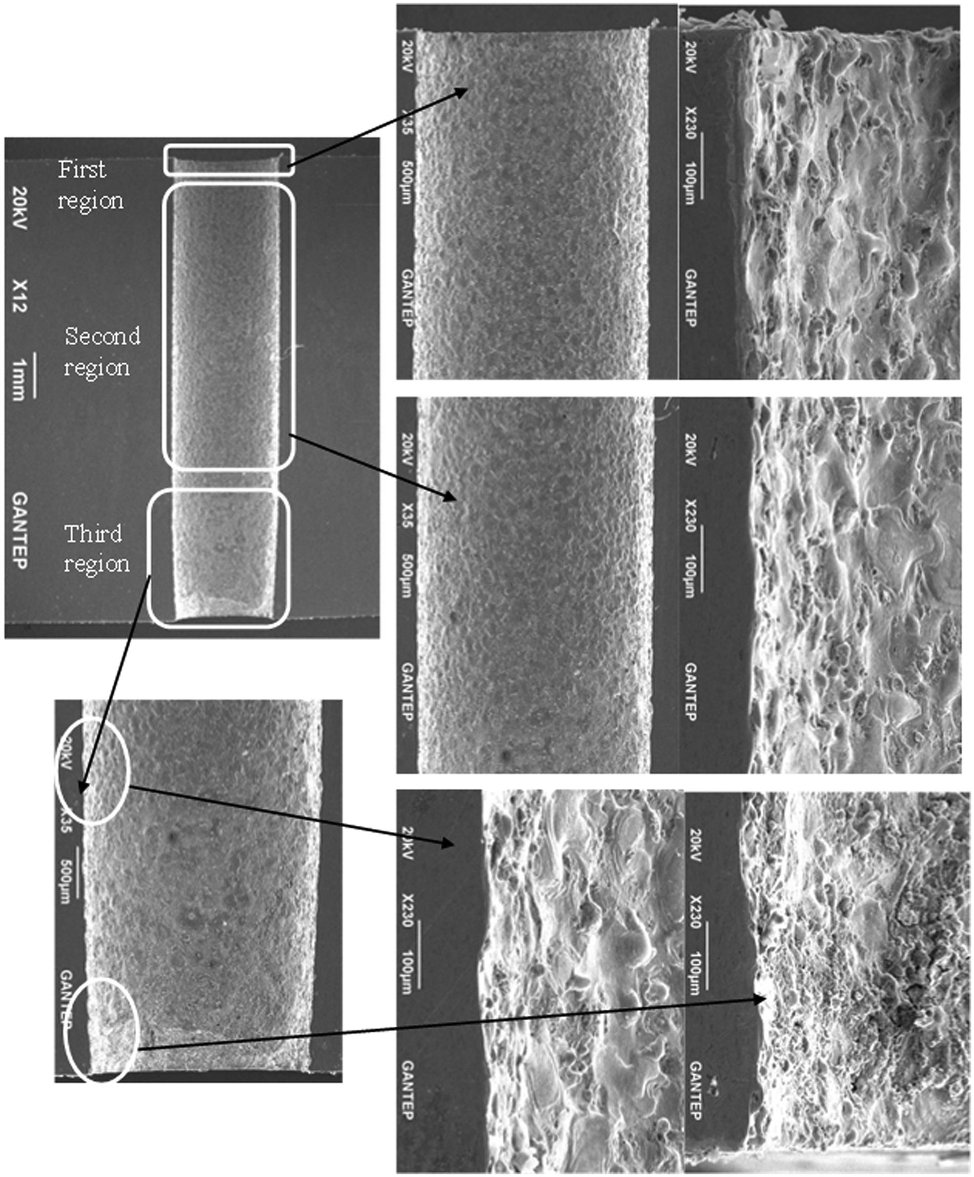
SEM view of different regions of a small hole.
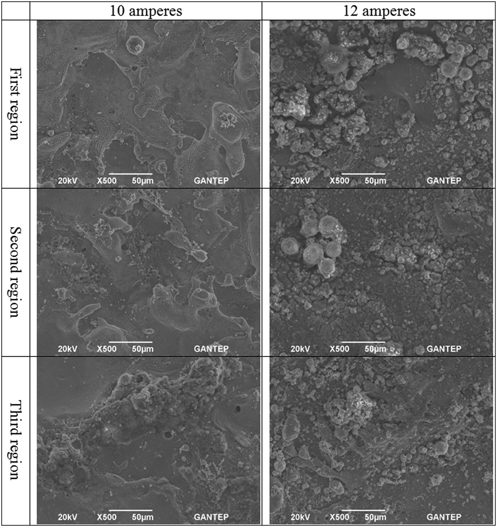
SEM view of the three regions of the hole for 10 and 12 A.
The second region is the longer part of the hole and it has straight walls. The process is relatively stable and the electrode wear could begin in this region of the hole. The melting followed by washing out starts on the surface, however, for 10 and 12 A formation of ligaments, and spherical features can be seen in Figure 8. Higher discharge currents result in bigger size of droplets. The removal of the debris depends on the flushing; if it is insufficient, proper and fast removal of debris from the surface will not occur. The remaining droplets stick to the surface; this makes the surface rougher.
In the third region, debris removal becomes extremely difficult. The accumulated debris enlarges the hole and also erodes the electrode. When the tip of the electrode reaches the bottom of the hole, the flow direction of the flush totally changes through the exit, so that there is no removal of the debris and the machining is stopped. Therefore, the surface roughness is very high, and the sticking debris can be seen from Figure 8.
Figures 9 and 10 show the results of surface roughness measurements. As the discharge current increases, so does the discharge heat concentration on the workpiece surface, which results in larger craters, that is, surface roughness. At a constant current, it was observed that Ra increased when pulse on-time increased. Because, when pulse on-time increased, spark energy will also increase and hence increases the surface roughness. Better surface quality was obtained when applying smaller discharge current and pulse on-time.
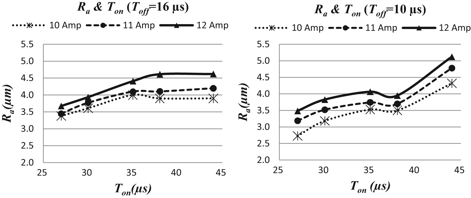
Effect of I and Ton on Ra when Toff = 16 and 10 µs.
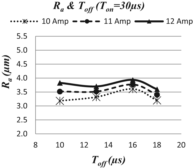
Effect of I and Toff on Ra when Ton = 30 µs.
The effect of pulse off-time on the surface roughness is shown in Figure 10. As a general trend, the increase in pulse off-time reduces surface roughness. There is a slight increase in the roughness for Toff = 16 µs. Insufficient pulse off-time does not allow efficient flushing, and so, it causes second arcing, and hence, increasing surface roughness and short pulse off-time allow less time for the removal of debris. Hence, higher pulse off-time is necessary for improved surface quality. However, long pulse off-time increases machining time; hence, it is desired that pulse off-time should be as low as possible, but in most cases, it should be selected based on the pulse on-time used for machining.
Effects on white layer thickness
The microscopic views of the white layers for different regions of the hole are given in Figure 11. The white layer thickness has a lowest value in the second region and a highest one at the exit. The enlargement of the hole in the lateral direction at the beginning of the taper due to the accumulated debris can be seen clearly from Figure 11(c).
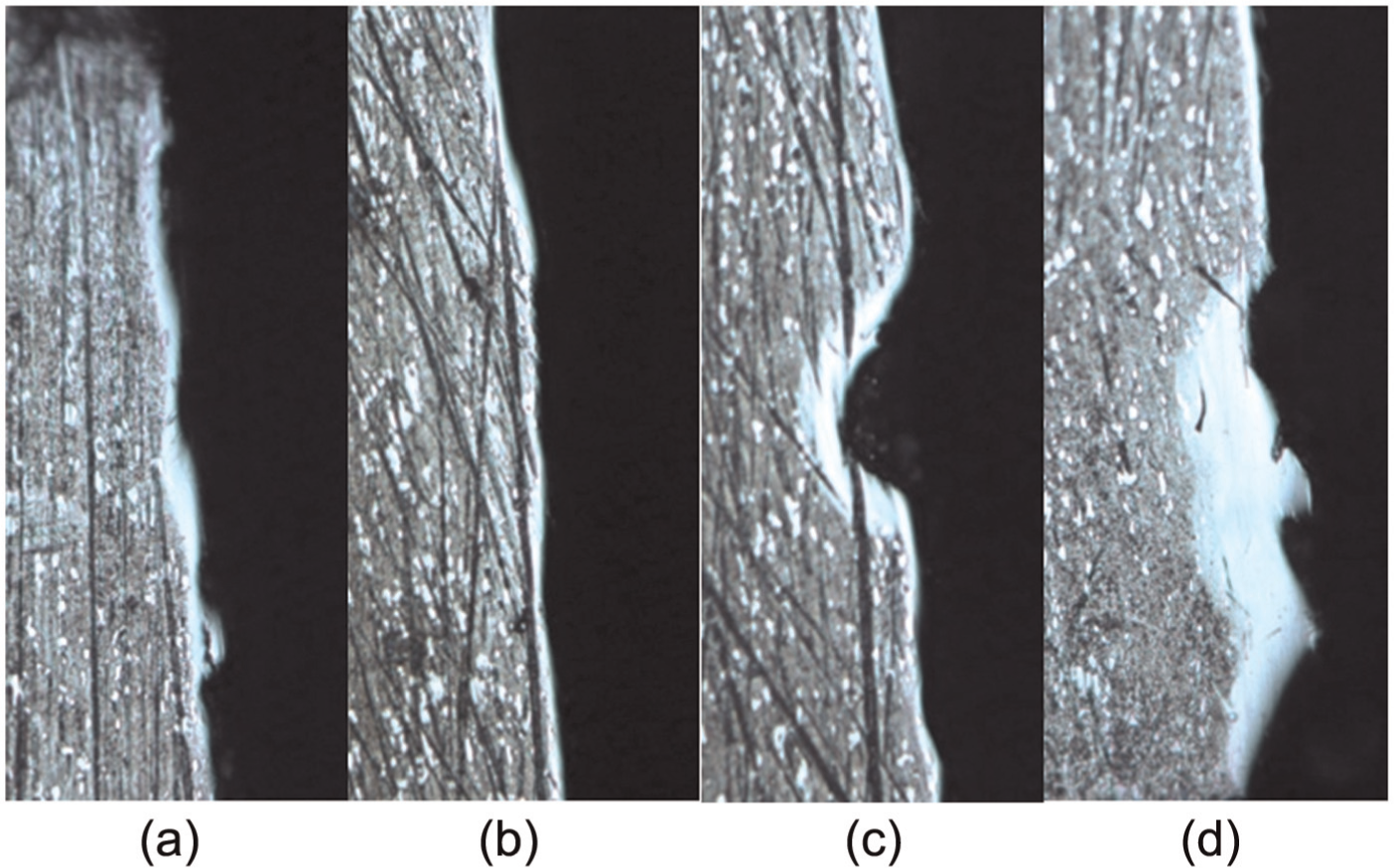
Microscopic views of the white layers for different regions of the hole: (a) first region, (b) second region, (c) taper begins and (d) exit.
The distribution of the average white layer thickness (AWLT) with respect to pulse on-time for different discharge currents is given in Figure 12. The AWLT decreases with increasing discharge current (Figures 12 and 13). However, the effect of pulse on-time on the AWLT is complicated, and it must be considered together with the pulse off-time. The white layer is generally formed by the sticking of the non-removed debris and also the depth of material affected from high temperature. The increase in Ton for the period of each discharge is the reason why conducted heat throughout workpiece increases. Thus, high temperature influences widespread zone on workpiece material, and the white layer gets thicker as well.
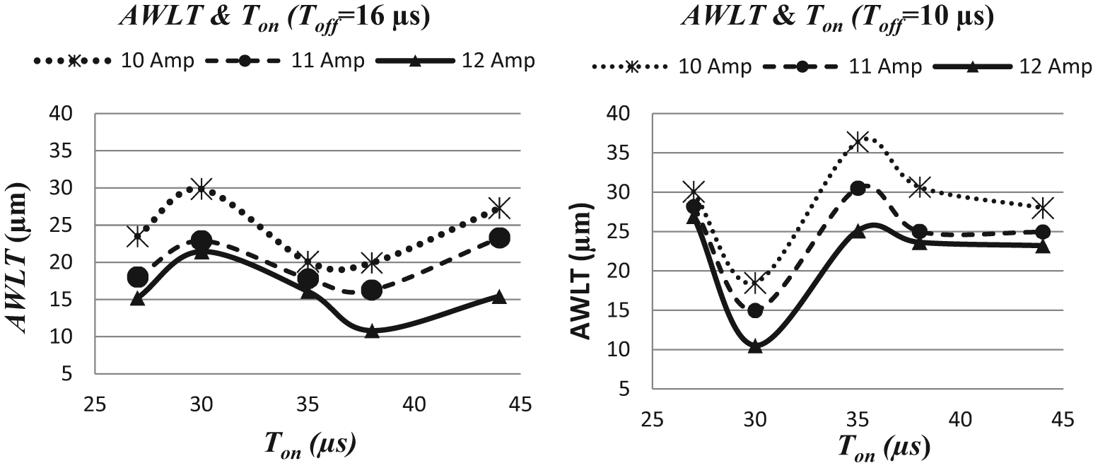
Effect of I and Ton on AWLT when Toff = 16 and 10 µs.
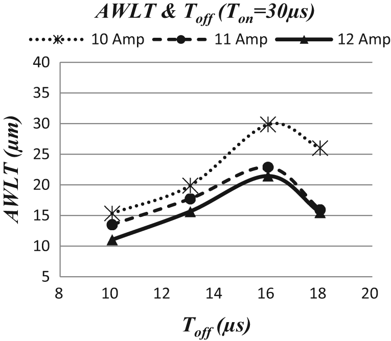
Effect of I and Toff on AWLT when Ton = 30 µs.
Effects on overcut and taper
The overcut (Oc) increases with increasing discharge current due to the higher spark gap, which melts and vaporizes more material from surface. The pulse on-time and pulse off-time affect the formation of the secondary spark during removal of the debris by pressurized liquid. Depending on the mutual effect of these two parameters (i.e. Ton and Toff), the amount of overcut scatters, as shown in Figures 14 and 15.
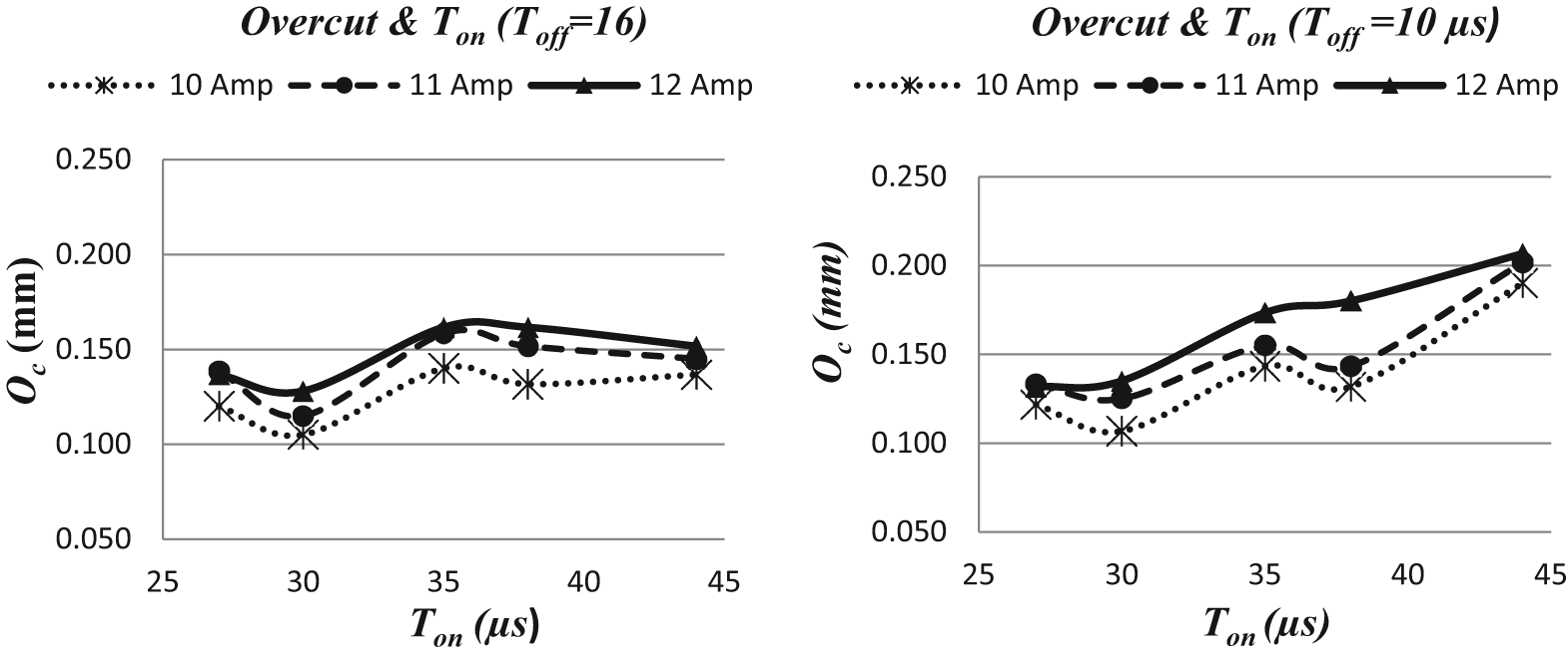
Effect of I and Ton on overcut when Toff = 16 and 10 µs.
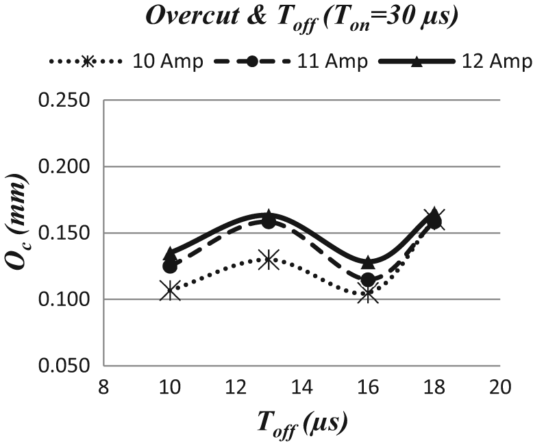
Effect of I and Toff on overcut when Ton = 30 µs.
The changes in taper lengths and taper angles with respect to pulse on-time and pulse off-time for 10, 11 and 12 A are given in Figures 16–19. The taper angle decreases with increasing discharge current; however, this is dependent on the taper length (equations (3)), where increasing length reduces the angle.
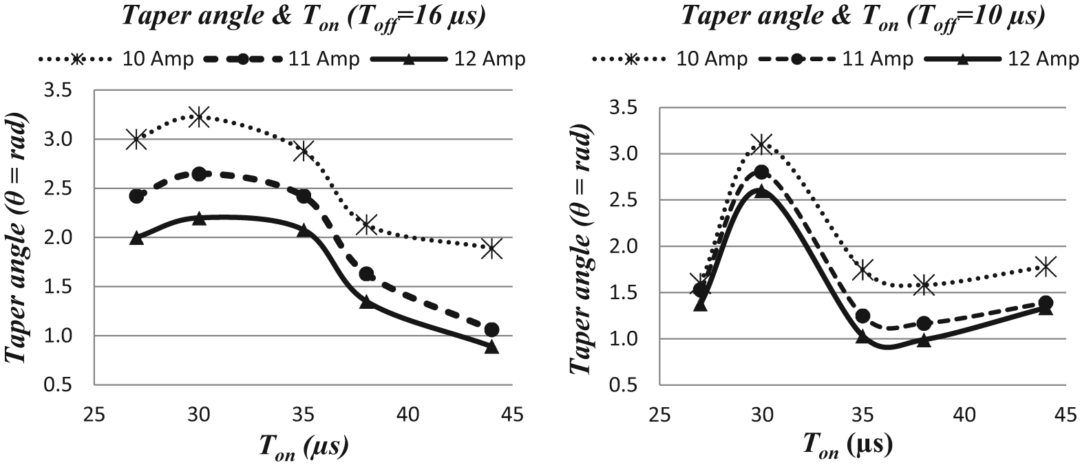
Effect of I and Ton on taper angle when Toff = 16 and 10 µs.
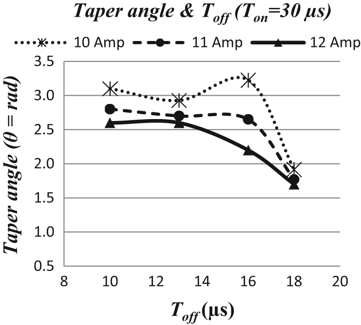
Effect of I and Toff on taper angle when Ton = 30 µs.
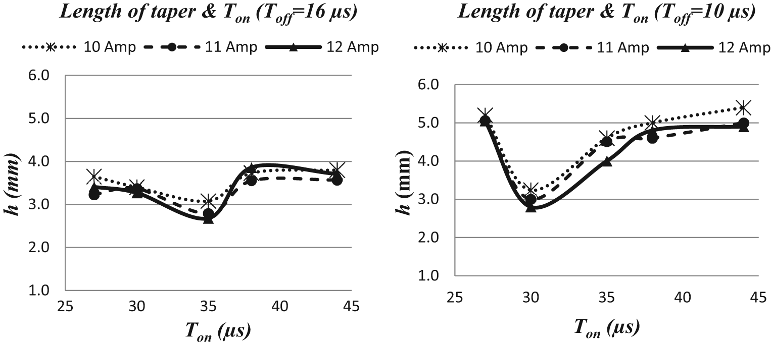
Effect of I and Ton on length of taper when Toff = 16 and 10 µs.
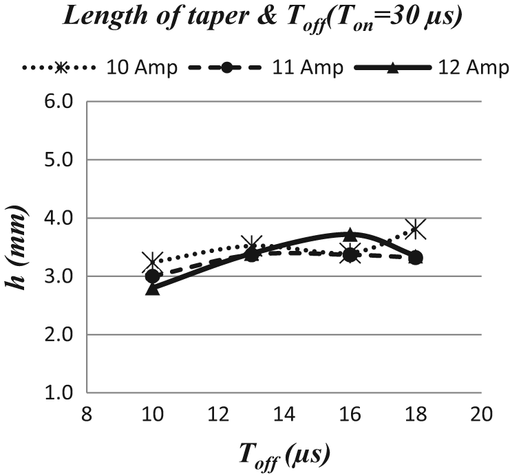
Effect of I and Toff on length of taper when Ton = 30 µs.
The effect of discharge current on the length of taper is less, as shown in Figures 18 and 19. This is due to increasing overcut and removal of the debris by increasing discharge current (see Figures 14 and 15). The selection of Ton and Toff has more effect on the length of taper.
Conclusion
In this article, the effects of electrical parameters on the small-hole EDM process were experimentally investigated. The MRR, surface roughness (Ra), AWLT, overcut (Oc), taper angle (
Results of the tests undertaken in this study (for ∅2 mm single-hole brass electrode) show that the lower discharge currents (I < 10 A) are not sufficient to evaporate the molten material properly and result in very low MRR (less than 0.06 g/min). The increase in discharge currents and pulse on-times improves the rate of melting and evaporation, so that MRR increases. Higher values of discharge currents (I > 12 A) cause very high electrode wear and very rough surfaces (Ra greater than 6 µm) due to formation of bigger molten metal crater on the workpiece.
Although minimal pulse off-time is required to increase MRR, a sufficient amount of pulse off-time is necessary to remove the debris between the electrode and the workpiece by the pressurized fluid. Insufficient pulse off-time (lower than 10 µs) causes secondary spark, so that the surface is rougher and there are more overcuts.
A compromise solution is required in selection of the EDM parameters (i.e. discharge current, pulse on-time and pulse off-time) to maintain machining stability (melting–evaporation and removal of debris). As the stability is maintained during the process, dimensional accuracy increases and a better finish can be obtained with a reasonable machining time. For ∅2 mm EDM hole drilling of DIN 1.2080 (X210Cr12) tool steel with single-hole brass electrode, choosing Ton = 27 µs and Toff = 10 µs gives better results in terms of surface integrity and MRR for all discharge currents (10–12 A).
The white layer is generally formed by the sticking of the non-removed debris and also the depth of material affected from high temperature. Since the long Ton causes the increase in conducted heat through the workpiece, heat-affected zone enlarges. So, the white layer thickness increases (changing between 10 and 35 µm).
Formation of taper at the bottom of the hole is inevitable; however, the length of the taper and the taper angle may be reduced by proper selection of the EDM parameters.
Footnotes
Appendix 1
Declaration of conflicting interests
The authors declare that there is no conflict of interest.
Funding
This study received financial support from Gaziantep University Scientific Research Council (BAP MF.09.10).