
Abstract
The article describes fabrication of an experimental setup which could be used for electrochemical drilling process to produce micro-holes in a copper workpiece with its different variants, namely, jet electrochemical micro-drilling, air-assisted jet electrochemical micro-drilling, ultrasonic-assisted jet electrochemical micro-drilling, and pulsed direct current–jet electrochemical micro-drilling process. Process parameters like voltage, electrolyte concentration, interelectrode gap, and electrolyte pressure have been selected to find out their effects on the process responses, namely, hole taper and material removal rate in all the above process. Attachments for air assistance and ultrasonic vibration application have been fabricated and incorporated in the setup. The effects of ultrasonic vibrations and the pulsed direct current voltage on the process responses like material removal rate and hole taper have been investigated. The effect of application of ultrasonic vibrations on the electrolyte jet has been studied. The experimental findings of ultrasonic-assisted jet electrochemical micro-drilling were compared with the findings of jet electrochemical micro-drilling. Similarly, the findings of pulsed direct current–jet electrochemical micro-drilling were also compared with the results of pulsed direct current ultrasonic-assisted jet electrochemical micro-drilling experiments. It has been found that the ultrasonic vibrations have significant effect on the two process responses. From the results, it was observed that with the use of ultrasonic vibrations, the material removal rate has increased to significant level and the hole taper has been decreased than in jet electrochemical micro-drilling. Effects of the pulsed direct current voltage supply on jet electrochemical micro-drilling and (ultrasonic-assisted jet electrochemical micro-drilling) were also analyzed. Application of pulsed direct current voltage has improved the material removal rate and reduced the hole taper in jet electrochemical micro-drilling as well as in ultrasonic-assisted jet electrochemical micro-drilling. The experimental results concluded that ultrasonic assistance have generated the holes with greater material removal rate and lower hole taper and with continuous direct current and pulsed direct current voltage.
Keywords
Introduction
The last few decades have shown tremendous growth and variations in the manufacturing activities. Industries like aerospace, electronics, nuclear reactors, and automobiles have been demanding products with higher precision and accuracy. Machining of newly developed materials with properties like increased strength, toughness, and hardness or properties like very light weight and delicacy have become prime challenge for the manufacturers. The requirements of dimensions of products have come down to micrometers and nanometers. 1 Applications like micro-drilling, slotting, and finishing of such products need very high quality and accuracy. Such precision machining processes require metal removal at atomic or molecular level to give excellent surface finish to the workpiece at micrometer or nanometer scale with extremely low material removal rate (MRR). 2 Machining of difficult-to-machine materials and cutting of complex contours on such materials are almost impossible or not economical with the existing traditional machining methods like turning, milling, and shaping. For these applications, newly developed processes such as laser beam machining, electron beam machining, ultrasonic machining, and electrochemical machining (ECM), and so on are used. The trend to obtain higher accuracy and precision on the difficult-to-machine materials is also directing the researchers toward the use of more than one principle of these machining processes at a time to have synergic effects which may lead to production of tighter tolerances, better quality, and surface finish on products. 3
In several areas like aerospace, electronics, and computer industries there is need of micro-hole drilling on the parts like nozzles, microcircuits, and turbine blades. For such applications, among the above-mentioned processes, ECM technique is gaining more preference for the reasons that there is no heat-affected zone surrounding the work area, almost no cutting forces act on the tool and the workpiece, no significant tool wear, the workpiece is free from mechanical impact, and residual stresses do not develop in the workpiece. The process is also independent of material properties like strength, hardness, and ductility of the material. The only requirement is that workpiece should be electrically conducting. ECM has variants like electrochemical grinding, electrochemical deburring, electrostream drilling, shaped tube electrolytic machining, and jet electrochemical machining (Jet-ECM), wherein fundamental principle of material removal is the same, that is, anodic dissolution but the tool configuration changes as per the process requirements. 2
This work is focused on development of a new process, that is, jet electrochemical micro-drilling (Jet-ECMD) process with ultrasonic vibrations which is a variant of Jet-ECM. Jet-ECM is a process extensively used for the drilling of holes of small sizes in hard and conducting materials. Jet-ECM can also be used for various other applications like removal and patterning of thin films, which is very important for electronic industry, etching and finishing applications, making small-diameter holes which are less than 1 mm diameter, machining grooves and slots, producing mask-less patterns for microelectronic parts, and machining contoured cavities without using a shaped electrode which needs moving of anode workpiece against the stationary electrolyte jet. 4 In Jet-ECM, acidic electrolyte of concentration, 20%–30% by weight, is forced to flow through the nozzle of small diameter with the pressure (0.3–1.0 N/mm2) to form a jet and is then impinged on workpiece. 3 The material is removed from the workpiece by controlled localized anodic dissolution in the form of metal ions. The removed material is washed away with the flowing electrolyte.
Researchers have been working on Jet-ECM to explore the maximum capabilities of the process and to improve the process performance. Kozak et al. 5 developed Jet-ECM machining setup to drill Inconel 600 alloy. Effects of the process parameters, namely, voltage, gap between electrodes, electrolyte pressure, and nozzle diameters on the MRR were investigated. They also developed the mathematical model to predict the shaping process with Jet-ECM which determined the correlation between the process parameters and the process response machining rate.
Sen et al. 6 performed drilling of small and through-holes in SUPERNI263A sheet with Jet-ECM process, and predictive model of the process was obtained from response surface methodology for process responses like MRR, radial overcut, and taper of the hole produced. The obtained model was optimized with genetic algorithm (GA) for the drilling of hole at maximum MRR with control over radial overcut and taper. They also concluded that the results of GA and experiments show good agreement.
Sen and Shan 7 conducted experiments of drilling hole in 0.5-mm thick SUPERNI 263 by Jet-ECM process and attempted to correlate various process parameters, namely, feed rate, electrolyte pressure, electrolyte concentration, and applied potential difference with responses like roundness error and surface roughness. They evaluated quality of drilled holes using roundness error and surface roughness and process productivity with the MRR. They reported that the electrolyte concentration and the applied voltage were the most significant factors affecting the process responses, and higher feed rate resulted in better surface finish.
Lu and Leng 8 drilled the micro-holes on titanium cylindrical workpieces using Jet-ECM. They found that the voltages below 100 V did not produce any indentation on the workpiece, and voltages above 250 V produced sparking between the tool and the titanium workpiece. Effect of jet pressure was analyzed, and it was observed that there was optimum value of pressure for stable machining. It was concluded that the Jet-ECM could be successfully used to machine the cylindrical titanium workpiece. Results were compared with the results obtained from another process named “through-mask electrochemical micro machining (TMEMM),” and it was found that Jet-ECM could drill holes with higher aspect ratio, but the hole quality was better in case of TMEMM process.
Sen and Shan 9 investigated the interactions between the process parameters effecting MRR, radial overcut, and hole taper. Process parameters like feed rate, electrolyte concentration, and material removal were found to influence the process responses significantly. They concluded that increase in current and concentration of electrolyte increased MRR, radial overcut, and hole taper, whereas the radial overcut and hole taper could be considerably reduced with the increase in feed rate of the electrochemical jet.
Sen and Shan 10 examined the effects of process parameters, namely, voltage, feed rate, electrolyte concentration, and interelectrode gap (IEG) on the roundness error and surface roughness of the generated hole with Jet-ECM process. Analysis of variance (ANOVA) was performed, and it was concluded that applied voltage and electrolyte concentration affected the roundness error significantly. Higher voltages and greater feed rate improved the surface finish but at higher values of voltage, the roundness error and hole taper increased. Higher values of inlet electrolyte pressure resulted in better surface finish because of improved removal of dissolved metal from the hole.
Natsu and colleagues11,12 fabricated a setup to machine three-dimensional surfaces with Jet-ECM process. They developed an algorithm to obtain the scanning path and speed of the nozzle to generate complicated pattern by superimposing simple patterns. Experiments were performed using sodium nitrate aqueous solution as electrolyte. Jet from nozzles of 0.42 and 0.26 mm diameter was impinged on SUS304 workpiece material. They observed that higher current densities resulted in good surface finish. They concluded that the depth of machined hole increased with longer machining time, but surface roughness values remained nearly constant for longer machining time. They have suggested a method to produce a complicated shape by superimposing simple grooves by scanning (moving) the nozzle.
Hua et al. 13 developed a 2D mathematical model to describe the profile of the drilled hole in laser drilling–assisted Jet-ECM. The simulated results from mathematical model were in good agreement with the experimental findings. They observed that during the process, the drilling of hole was executed with the laser while the Jet-ECM assistance reduced the recast layer formation which was removed with the electrochemical action of jet, and the spatters observed were less due to effective cooling of the machined area and removal of debris formed during the process. This improved the quality of holes significantly but reduced the efficiency of the process in terms of MRR due to part of laser energy absorbed by electrolyte which was found to be 70% more in case of laser drilling in air.
Hua and Xu 14 developed a 2D model for the prediction of the shape of a drilled hole with Jet-ECM process. The simulated results were compared with the actual results obtained from the experiments, and it was reported that the Jet-ECM process gave better results at voltages more than 120 V and for drilling of holes of diameters less than 1 mm. It was also noted that during the drilling process, the material removal occurred in radial direction and then along the depth of the hole with increased machining time.
Hackert et al. 15 simulated the Jet-ECM process with the COMSOL multi-physics software to predict the correlation between the nozzle diameter and the dimensions of the hole produced. The authors concluded that the depth of the holes increased with the increase in the diameter of the nozzle. This increase in depth of the hole was not found linearly proportional to increase in diameter of the nozzle.
Yiquan et al. 16 drilled small-sized hole on stainless-steel (SS) sheet of 0.5 mm thickness with Jet-ECM process. They studied the effects of direct current (DC) and pulsed DC supply on the quality of hole and the process performance. From the experimental findings they concluded that use of pulsed DC resulted in reduced taper of hole than that of DC, and the area of scattered corrosion was lesser in case of pulsed DC resulting in good quality of the drilled hole.
Kai et al. 17 developed a method to cut the metal sheets with Jet-ECM process. They incorporated coaxial flow of assist gas through the nozzle of electrolyte flow. They reported that the coaxial gas flow reduced the momentum in the flow of electrolyte and shifted the hydraulic jump away from jet impingement area. It was observed that the required electrolyte film flow for drilling could be obtained at lower flow rate of the electrolyte with the assist gas flow.
Qadri and Sharma 18 investigated the effect of suspended abrasives into the electrolyte in ECM process. Silica abrasives were mixed with sodium chloride aqueous electrolyte, and influence of the abrasives was observed on the MRR and surface roughness. They reported that the MRR increased with the use of abrasives with increasing feed rate, whereas the surface roughness reduced due to the polishing effect of abrasives.
Yang et al. 19 conducted micro-ECM with ultrasonic vibrations. Ultrasonic vibrations were passed into the electrolyte by vibrating the electrolyte tank. They observed that the application of ultrasonic vibrations reduced the machining time up to 87% as it enhanced the electrolyte diffusion and reduced the bubble interference in the machining gap. The surface quality of the holes drilled was also found to be increased as a result of enhanced removal of dissolution products and increased flow of electrolyte with increased hole depth.
Natsu et al. 20 fabricated an experimental setup to improve the processing speed and accuracy of the ECM process with the aid of ultrasonic vibrations with various patterns. The ultrasonic vibrations were given to the tool in both longitudinal and transverse directions. The effects of amplitude of the ultrasonic vibration and its direction were investigated. They concluded that the speed and accuracy were improved with the application of ultrasonic vibration in both longitudinal and transverse directions to the tool due to better removal of the byproducts from the IEG.
Ruszaj et al. 21 investigated the effects of ultrasonic vibrations on the process responses, namely, surface roughness, IEG, and current density in ECM process. They observed that the surface roughness depended on the power of ultrasonic vibrations and the voltage applied across electrodes at constant feed rate. They also incorporated pulsed DC voltage along with the ultrasonic vibrations to the tool electrode. They observed that the surface profiles of the workpieces changed with the application of ultrasonic vibrations. At higher power of ultrasonic vibrations, the surface roughness values were found to increase.
Nicoara et al. 22 investigated the effect of application of ultrasonic energy in ECM process. It was found that the metal removal rate increased with ultrasonic assistance and was more at higher ultrasonic frequency.
Skoczypiec 23 performed the numerical analysis of the electrolyte flow through the IEG in ultrasonic-assisted ECM process. The tool was given ultrasonic vibrations of 10 µm amplitude and 20 kHz frequency. From the analysis, they concluded that ultrasonic vibrations induced a pressure gradient perpendicular to the electrolyte flow. The experimental investigations of the process showed that with ultrasonic assistance the dissolution conditions of the electrolyte changes.
Pa 24 incorporated ultrasonic and magnetic assistance to the ECM process. It was observed that with increase in frequency and power of ultrasonic vibrations, the surface finish improved due to the efficient removal of the discharge from the machining area with the ultrasonic and magnetic assistance.
Goel and Pandey 25 conducted experiments with coaxial air flow in Jet-ECMD to drill micro-holes in the copper. The coaxial air was passed along with the electrolyte jet, and it was found that localization of the current density into the machining area occurred which reduced the overcut significantly.
Liu et al. 26 performed experiments with abrasive slurry jet machining, electrochemical jet machining, and electrochemical slurry jet machining processes and reported that electrochemical slurry jet machining had greater MRR than the other two processes.
Kawanaka and Kuneida 27 machined mirror-like surface finish with Jet-ECMD process. The improvement in surface roughness was observed when the electrolyte jet was reciprocated at high translation speed. They suggested use of bipolar pulse current method for achieving the mirror-like surface finish.
From the literature review, it was observed that Jet-ECM is a potential process for micro-drilling, but it works with extremely low MRR, low aspect ratio, and high hole taper. The reasons being, the dissolved products could not be effectively flushed away from small size of hole and overcutting at micro-gaps between the jet and the sidewalls of the drilled hole. The flaring of the pressurized electrochemical jet also results in adverse effect on the dimensions of the entry diameter of the hole. The machining accuracy in terms of diameter of the drilled holes also depends on the localization of the current density under the electrolyte jet impinged on the workpiece. The localization of current density was found to improve with flow of air coaxially with the electrolyte jet which shifted the hydraulic jump away from the machining zone, as shown in Figure 2. To minimize the hole taper and to increase the MRR and aspect ratio of the drilled hole, many investigations16–18 have been done among which hybridization of ECM process with another technology is one of the alternatives. Use of ultrasonic energy in the ECM process has been investigated by researchers,19–24,28 and it was proved that the tool vibration with ultrasonic frequency improved the performance of the process. Two different methods were used to apply the ultrasonic vibrations in the ECM process as the direct ultrasonation, 23 where the tool cathode was ultrasonically vibrated and the indirect ultrasonation in which electrochemical cell was immersed in the ultrasonically energized liquid bath (electrolyte). It was found that in ECM process, ultrasonic vibrations have improved the reactions in the working gap, and better removal of dissolution products from the working gap resulted in the enhancement of electrolyte diffusion process. It is evident from the above literature review that the application of ultrasonic vibrations has showed significant effect on the machining performance in ECM process. However, no attempt appears to be made to integrate ultrasonic vibrations with Jet-ECM process. The concept of acoustic liquid manipulation (ALM) has been recently used to focus the metallic ions for better electrochemical metal deposition. 29 With ALM, the purpose is to stimulate the fluid motion in the electrolyte jet by passing the additional acoustic energy to enhance the mass transport of the electrochemical reactive species to the machining zone. The potential of ALM concept may be exploited to drill micro-holes with higher machining rates and accuracy. The proposed work is an attempt to focus on improving the Jet-ECMD process performance by increasing the MRR and reducing hole taper. Therefore, in this study, an experimental setup has been developed to pass ultrasonic vibrations to the machining zone through the electrolyte jet to get the effect of acoustic manipulation in the electrolyte, and also the attachment to pass the coaxial air flow along with the electrolyte jet to concentrate the current density in the machining area was incorporated in the setup. Effect of ultrasonic vibrations along with various parameters like voltage (DC and pulsed DC), electrolyte concentration, electrolyte pressure, and IEG was investigated on Jet-ECMD process responses such as MRR and hole taper. Thus, four alternatives of Jet-ECMD were compared for the performances. Following section discusses the fabrication of the setup and experimentation work.
Details of the experimental setup
The fabricated experimental setup of Jet-ECMD process along with attachment for passing the ultrasonic vibrations (UJet-ECMD) into the electrolyte jet has been shown in Figure 1(a) and (b). UJet-ECMD mainly consisted of four major elements as electrolyte supply system, air flow supply system, electrochemical cell, and ultrasonic head.
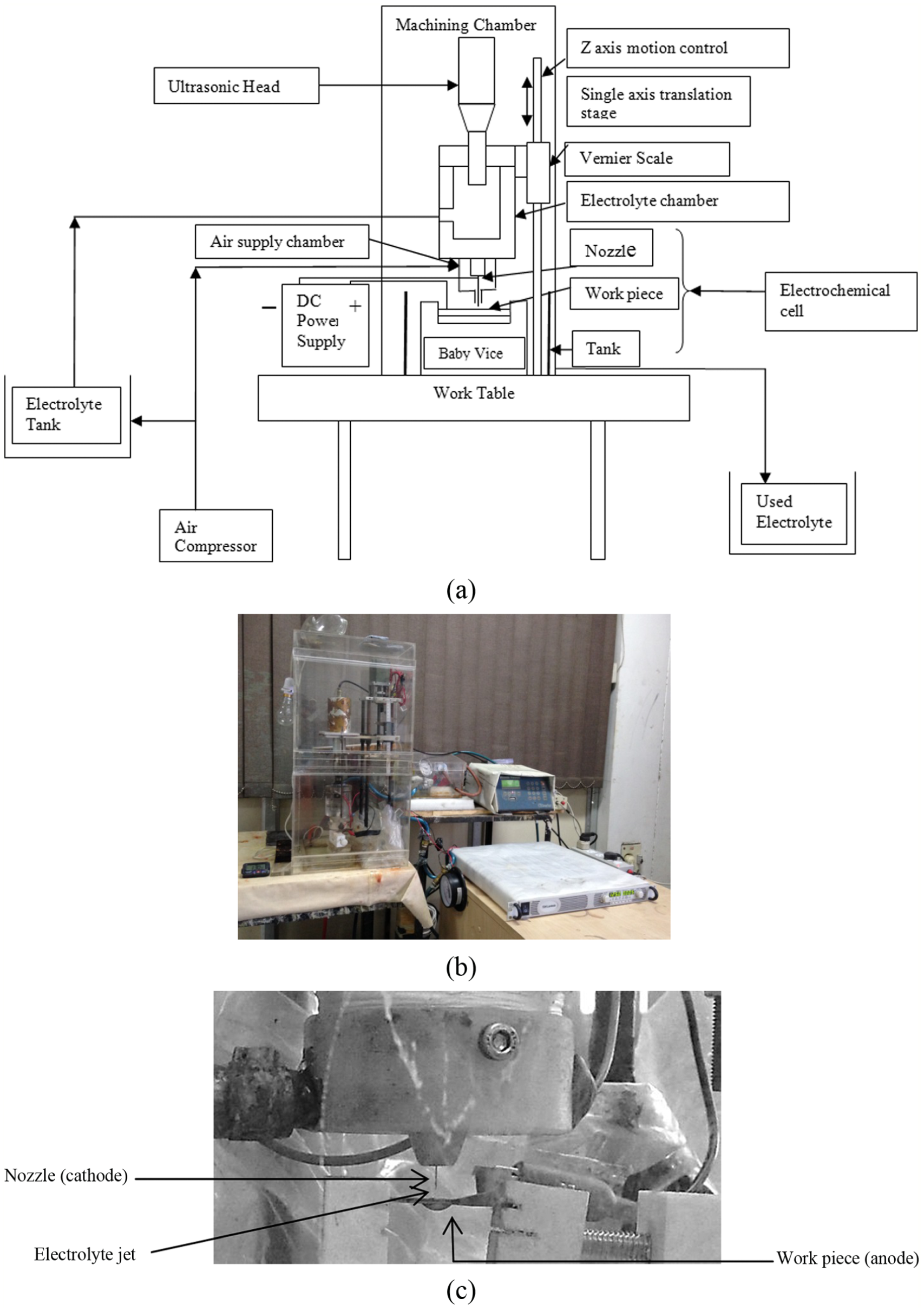
(a) Schematic diagram of the fabricated experimental setup, (b) experimental setup developed, and (c) electrochemical cell micro-nozzle and workpiece.
Electrolyte circulation system had the electrolyte tank and the compressor with pressure gauge. The compressed air from the compressor was passed into the electrolyte tank to supply the electrolyte with suitable pressure. Filter was mounted near the nozzle assembly to reduce the frequent clogging of the nozzle. Electrolyte entered into the nozzle assembly and emerged out as electrolyte jet from micro-sized nozzle with high pressure. Another tank placed below the nozzle assembly had the workpiece held into the vice at proper position. This tank also collected the used electrolyte and the reactants which were then drained off. Electrochemical cell, as shown in Figure 1(c), consisted of SS nozzle cathode of 140 µm diameter, as shown in Figure 2, and copper workpiece, and suitable fixture (baby vice). High-voltage (0–600 V, TDK-Lambda) DC power supply has been used to apply voltage across the workpiece and the nozzle. Nozzle and copper workpiece were made cathode and anode, respectively.
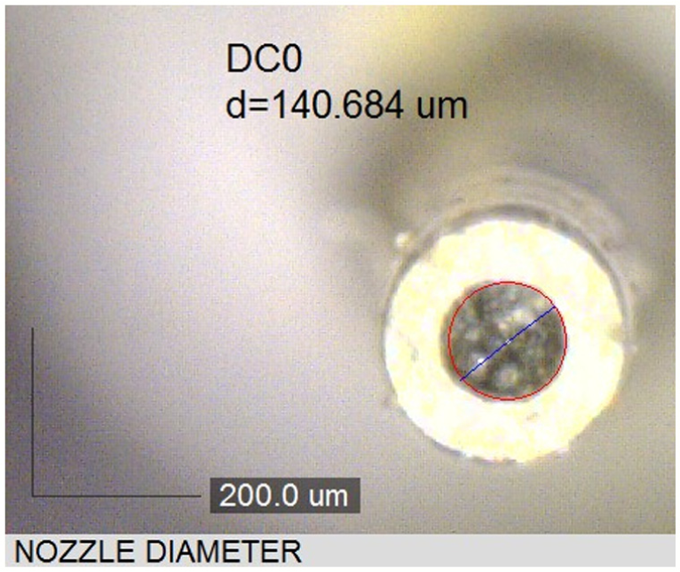
Measurement of nozzle diameter.
Electrochemical jet when impinged on the workpiece completed the electrical circuit in the electrochemical cell. The electrolyte jet when impinged on the workpiece, the electrolyte flowed outward in radial direction around the jet in thin layer, and the hydraulic jump was formed, as shown in Figure 3(a). The current density gets concentrated under the area of electrolyte jet due to this thin layer, and the hydraulic jump shifted away from the point of impingement for concentration of the current density at small jet area. High current density concentrated at small jet area results in selective machining of the workpiece under the jet with nearly no material removal in the area of thin electrolyte layer. 12 If the height of hydraulic jump is more and if it contacts the nozzle tip, short circuit is likely to happen due to the high voltage between nozzle and workpiece. Hence, attachment to pass air with the electrolyte jet, as shown in Figure 3(b), has been fabricated.
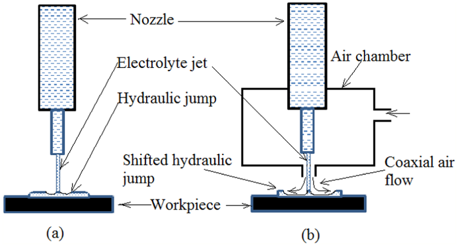
Principle of Jet-ECMD: (a) Jet-ECMD and (b) Jet-ECMD with coaxial air flow.
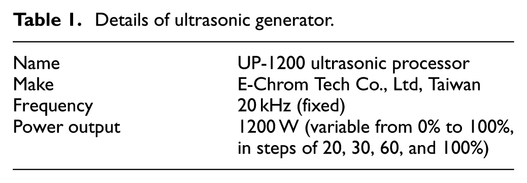
The compressed air was passed into the air chamber which flows coaxial with the electrolyte jet. The air supply unit had a pressure gauge and the control knob to adjust the value of the air pressure. The coaxial air supply with the electrolyte jet shifted the hydraulic jump away from the impinging jet area enabling the electrolyte to flow in thin layer radially after striking the workpiece. This improved the machining conditions by reducing the spark occurrence due to high voltage between the nozzle and workpiece surface and concentrated the current density under the electrolyte jet which resulted the smaller diameters of drilled hole. The attachment to pass the ultrasonic vibrations into the electrolyte jet consisted of piezoelectric transducer, ultrasonic processor, and ultrasonic horn which had been fabricated, as shown in Figure 4, to obtain the effect of acoustic manipulation over the ions into the electrolyte. The ultrasonic transducer along with a horn was mounted over the electrolyte chamber. The electrolyte chamber had the horn at one end and the nozzle at other end, as shown in Figure 4. The details of the ultrasonic generator have been given in Table 1. The piezoelectric transducer can generate vibrations of 20 kHz frequency that were passed into the electrolyte chamber through horn to the electrolyte jet. The ultrasonic head was mounted on z-slide to move in Z-direction to adjust the required IEG, that is, distance between the nozzle tip and workpiece surface. Digital vernier caliper has been attached to measure the value of gap. The ultrasonic horn, nozzle assembly, electrochemical cell, and z-slide mechanism were kept enclosed in the machining chamber for safety as high voltage and the high-pressurized electrolyte flow were involved in the process.
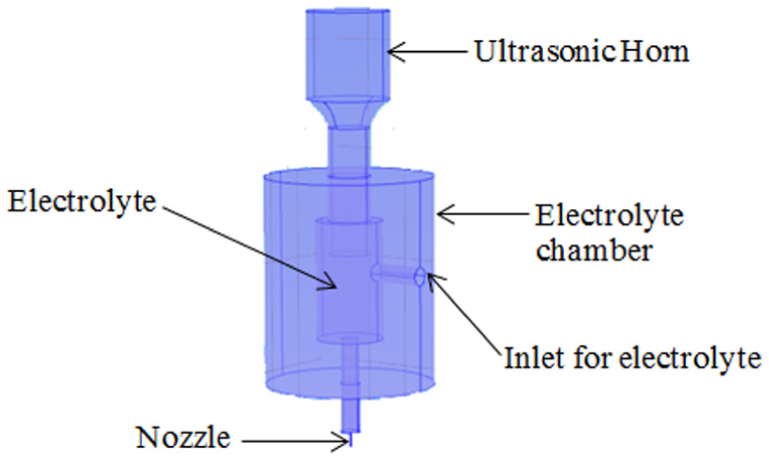
Schematic diagram of nozzle assembly with ultrasonic horn and electrolyte chamber.
Details of ultrasonic generator.
Details of experiments
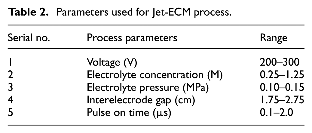
In this work, effects of process parameters on responses of Jet-ECMD process, namely, MRR and hole taper were studied. One process parameter was varied at a time and the others were kept constant to study the two responses. Copper sheet of 350 µm thickness has been selected as workpiece material and SS nozzle cathode has diameter of 140 µm. Diluted sulfuric acid has been selected as electrolyte. Based on the literature survey, five parameters were chosen as applied voltage: electrolyte concentration, electrolyte pressure, IEG, and pulse on time (in case of pulsed power supply) to predict the process responses, whereas the air pressure has been kept constant for all the experiments. The concentrations were changed by controlling the amounts of sulfuric acid and water content into the solution. The range for electrolyte concentration was selected from 0.25 to 1.25 M of diluted sulfuric acid aqueous solution as above 1.25 M H2SO4 concentration, and sparking in the gap between electrodes occurred due to very high current and rise in temperature of the electrolyte. Based upon the trial experiments, the range for the electrolyte jet pressure for selected voltage range is chosen between 0.1 and 0.15 MPa. At lower value than 0.1 MPa, the jet was not stable in a way that the applied coaxial air was deflecting the electrolyte jet resulting in production of the oval and irregular-shaped holes, as shown in Figure 7(b). At the higher values than 0.18 MPa, the electrolyte was causing backflow of the electrolyte after striking the workpiece during the machining process, as shown in Figure 7(c). The contact of this pressurized electrolyte flowing in backward direction with the high-voltage negatively charged nozzle, resulted into sparks between the nozzle and the workpiece. This resulted into damage and welding of the nozzle tip due to high temperature of the sparks produced at high voltage, which would need frequent replacement of the nozzle. For this work, the values of the IEG were selected between 1.75 and 2.75 mm, as shown below 1.75 mm sparking occurred between the nozzle and workpiece at preset voltage values. So, the lower limit of IEG was set to 1.75 mm and other four values were selected above it in equal intervals.
Process parameters used to perform Jet-ECMD experiments are given in Table 2. After performing the Jet-ECMD experiments, UJet-ECMD experiments were performed for all the process parameters with applying ultrasonic vibrations into the electrochemical jet. For UJet-ECMD, the pulse on time of 0.5 s and pulse off time of 0.5 s were kept constant for ultrasonic vibrations, and power output was selected as 60% throughout all the experiments. Again the set of experiments was conducted by changing continuous voltage with pulsed DC voltage with nanopulses in the range given in Table 2. For this set of experiments, pulsed DC (Make—Electronica machine tools) power supply was used for both Jet-ECMD and UJet-ECMD processes.
Parameters used for Jet-ECM process.
To determine the values of process responses, the entry diameter and exit diameter of the drilled hole, time required in drilling the hole, initial and final weights of the workpieces, and machining current were measured.
The weights of the workpiece before drilling and after drilling were measured using electronic balance (Make—Shimadzu, least count 0.1 mg). The drilling time was measured in seconds with the stopwatch to calculate the MRR. Drilling of through-holes was ensured with the jet coming from the bottom side of the workpiece and the current value as zero which was observed in the ammeter of the power supply. The workpiece was cleaned and its optical images were taken with Dino-Lite 2.0 digital microscope for getting the entry diameter and exit diameter measurements of the hole to calculate hole taper in degrees from their difference. The results were obtained for both the processes, that is, Jet-ECMD and UJet-ECMD and then analyzed to draw the conclusions.
Results and discussion
Following section presents the results graphically and discusses the effects of various parameters on MRR and hole taper.
Effect of process parameters on MRR
Effect of voltage
The effect of voltage on MRR for Jet-ECMD and UJet-ECMD has been shown in Figure 5(a), which shows that increase in voltage has increased the MRR. However, the increase of MRR with voltage is higher in case of UJet-ECMD as compared to Jet-ECMD. In Jet-ECMD, the dissolution of anode (copper) is governed by Faraday’s laws and hence it was proportional to the amount of current passing through the electrolyte. According to Ohm’s law, I = V/R and therefore, in the Jet-ECMD, current is proportional to the applied voltage as resistance of the electrochemical jet is constant for particular distance between anode and cathode. With increase in voltage, the current in the electrolyte increased, which increased the rate of electrochemical reactions and thus the rate of anodic dissolution or MRR was increased as depicted from Figure 5(a). The obtained curve for voltage versus MRR was nonlinear for the reason that at higher voltages, the conductivity of the gap between the nozzle and workpiece increased due to the dissolved metallic ions.
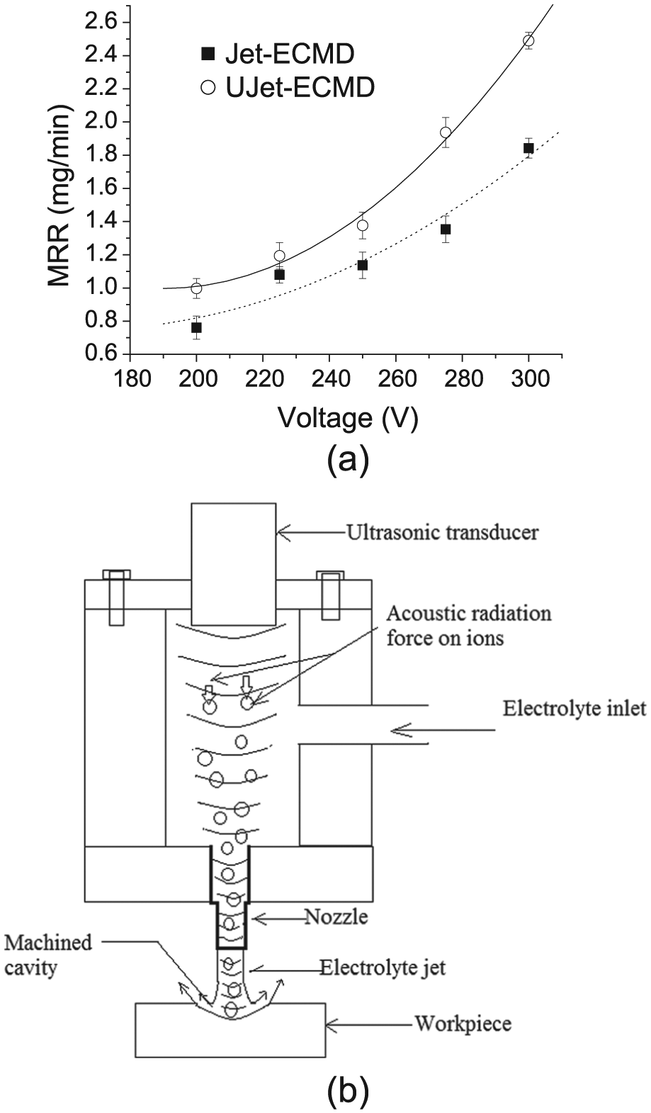
(a) Variation of MRR with applied voltage (IEG 2.25 mm, pressure 0.13 MPa, 1M H2SO4) and (b) acoustic radiation force acting on the ions in electrolyte due to ultrasonic vibration.
Ultrasonic assistance in Jet-ECMD helped to remove the reaction products from the machining area 22 effectively and allowed the fresh electrolyte to flow into the IEG which increased the MRR due to enhanced electrochemical reactions. Apart from this, ultrasonic waves passed into the electrolyte jet manipulated the electrochemical species by focusing the electrons to the machining zone. Acoustic manipulation of the charged particles in the direction of the propagation of the wave 26 toward the workpiece took place due to acoustic radiation force acting on them, as shown in Figure 5(b). This increased the rate of electrochemical reactions due to increased number of ions per unit time available which resulted in increased MRR. When compared with MRR of Jet-ECMD without ultrasonic assistance, it was observed that the application of ultrasonic vibrations has increased the MRR up to 40%.
Effect of electrolyte concentration
Figure 6 shows the plot obtained between the electrolyte concentration and MRR for both Jet-ECMD and UJet-ECMD processes. As evident from the graph, MRR increased with increase in electrolyte concentration for both the processes. Increase in electrolyte concentration increased the electrical conductivity which in turn increased the current density of the electrolyte jet. At higher current density, the MRR increases. 5 At higher concentrations of the electrolyte, the current density for machining was more due to dissociation of large number of free ions with fixed distance between electrodes at a specific value of applied voltage. With higher current density, the number of conductive ions participating in the electrochemical reactions was increased. This increased the rate of electrochemical reactions and the amount of dissolution of anode. The increase in MRR of the UJet-ECMD with electrolyte concentration was found more than the Jet-ECMD; the reasons contributing the increase in MRR may be that ultrasonic waves into the electrolyte jet were carrying away the reaction products from the machining area effectively during the pulse on time and inducing the supply of fresh electrolyte into the IEG.
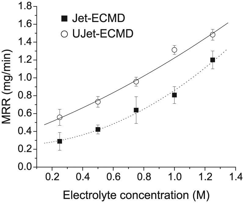
Variation of MRR with electrolyte concentration (voltage 250 V, IEG 2.25 mm, pressure 0.13 MPa).
The loss of conductivity of the electrolyte due to hydrogen evolution during the electrochemical reactions was also compensated with the fresh electrolyte introduced with faster rate into the gap. The agitation in the supply of ions toward the machining zone with the acoustic force due to ultrasonic waves in the direction toward workpiece also increased the reaction rate. As more numbers of ions were available for the reactions due to above reasons, it improved the rate of electrochemical reactions and the MRR up to 17% in case of UJet-ECMD.
Effect of electrolyte pressure
Figure 7(a) shows the effect of electrolyte pressure on the MRR in both Jet-ECMD with and without ultrasonic vibrations. The MRR increased with the electrolyte pressure in both Jet-ECMD and UJet-ECMD as depicted in Figure 7(a). The metallic dregs from the electrochemical reactions and the hydrogen gas evolved during the process get collected in the small gap between the electrodes, which resulted in reduction in anodic dissolution rates. With increase in pressure, MRR increased as the flow of fresh electrolyte enters into the IEG and machined cavity and removed the heat and the reactants produced. In the case of UJet-ECMD, higher values of MRR were observed than Jet-ECMD because the ultrasonic waves during its pulse on time improved the rate of cleaning of the dregs and gaseous products form the gap and increased the concentrated supply of ions into the machining zone to further enhance the rate of electrochemical reactions. The application of ultrasonic waves has increased the MRR up to 38% in UJet-ECMD as compared to Jet-ECMD.
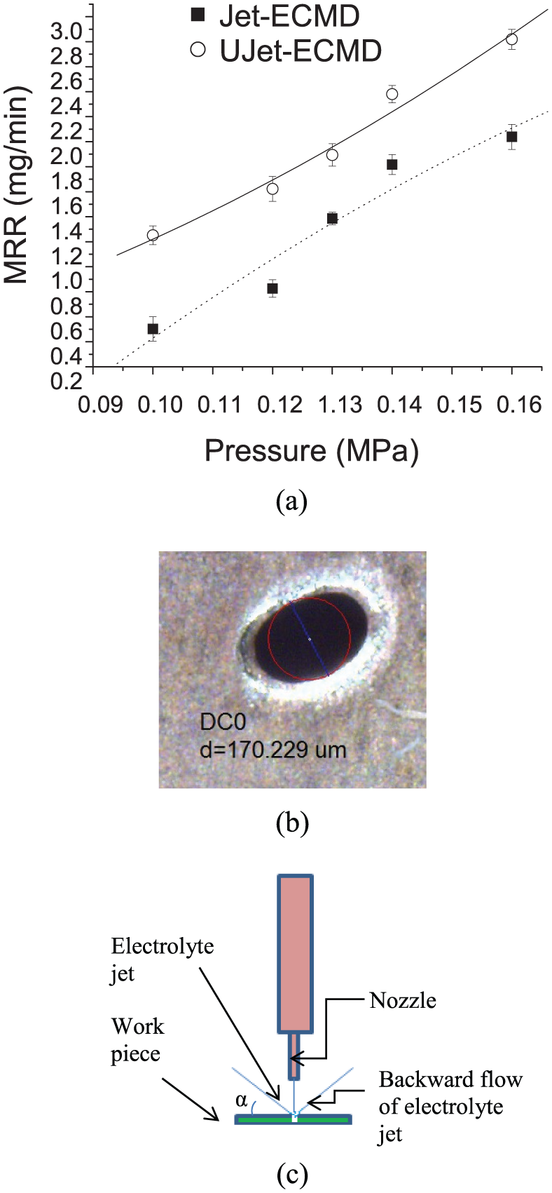
(a) Variation of MRR with electrolyte pressure (voltage 250 V, IEG 2.25 mm, 1M H2SO4), (b) oval shape of hole, and (c) electrolyte backward flow at high electrolyte pressure.
Effect of IEG
Figure 8 shows the plots obtained between the MRR and different values of IEG for Jet-ECMD and UJet-ECMD processes. It can be observed from the obtained graph that the MRR decreases with increase in the IEG in both the processes. The metal removal process in Jet-ECMD is governed by Faraday’s law and Ohm’s law. Current density is inversely proportional to the distance between the electrodes. With the increased distance between cathode nozzle and anode workpiece, the length of the conducting electrolyte jet increased. Due to this, resistance to the flow of current into the electrochemical cell increased decreasing the current density in the IEG. Due to this, MRR in both the UJet-ECMD and Jet-ECMD processes decreased with increased IEG. MRR was found to be more in UJet-ECMD than the Jet-ECMD due to the reason that the ultrasonic vibrations concentrate more number of ions into the machining zone due to acoustic radiation forces acting on the ions. Due to the increased ion concentration, the rate of electrochemical reactions increased resulting in higher values of MRR in UJet-ECMD.
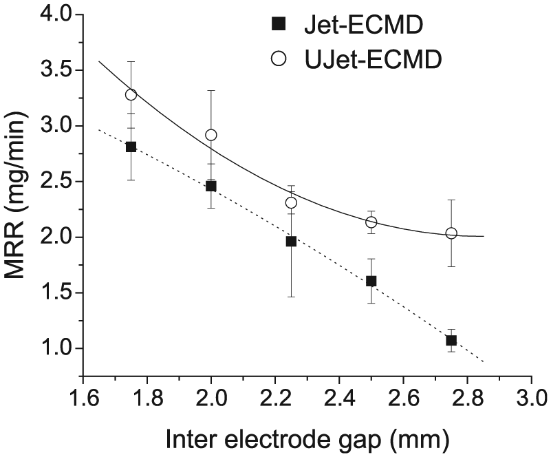
Variation of MRR with interelectrode gap (voltage 250 V, pressure 0.13 MPa, 1M H2SO4).
Effect of Ton time of pulsed DC voltage
Figure 9 shows the effect of the DC pulses of voltage on MRR in the Jet-ECMD and UJet-ECMD processes. It can be seen that MRR increased with the increase in the pulse on time of the pulsed DC voltage. The increase in MRR was found more significant in UJet-ECMD than Jet-ECMD process. During the Jet-ECMD process for producing the micro-hole, due to very small diameter of the hole, the MRR decreased with time as the conductivity of the electrolyte decreased with the accumulation of reaction products in the IEG and in the very small microcavity inside the hole. In Jet-ECMD with pulsed DC voltage, machining occurs only during the pulse on time, whereas during the pulse off time, the electrolyte jet cleans off the machining products 16 from the machined cavity and allows the fresh electrolyte to enter the cavity for further machining by electrochemical reactions. The higher MRR in the UJet-ECMD may be due to the reason that during the pulse on time of the DC voltage, ultrasonic vibrations caused the acoustic streaming of the electrolyte jet thus concentrating the flow of ions toward the machining zone enhancing the rate of electrochemical reactions.
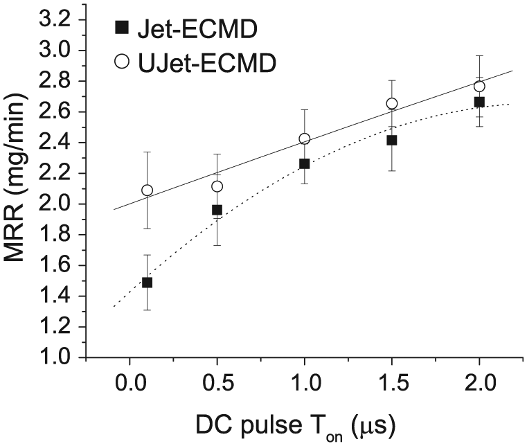
Variation of MRR with pulse on time (pulsed DC-applied voltage) (voltage 270 V, IEG 2.25 mm, pressure 0.13 MPa, 1M H2SO4, pulse off time (DC voltage) 3 µs, pulse on time ultrasonic vibrations = 0.5 s).
Effect of process parameters on hole taper
Following section discusses the effect of various process parameters as on hole taper.
Effect of voltage
Figure 10(a) shows the variation of hole taper with respect to applied voltage for both Jet-ECMD and UJet-ECMD processes. It can be seen that the hole taper was increased with the increase in voltage for both the processes, whereas the magnitude of hole taper was observed less in case of UJet-ECMD. In Jet-ECMD process, in the machining zone, the resistance of the electrochemical jet was constant for the constant IEG, and the diameter of the jet was also constant, so the area under the electrolyte jet was constant. Therefore, the current density was directly proportional to the current which was proportional to the applied voltage. During the total machining time, the electrolyte jet remained in contact for greater time at the entry side of the hole or at the top surface of the anode than the exit side. Due to this, more material was removed at the entry side of the hole than the exit side of the hole as shown in Figure 10(b). The non-linearity in the curve obtained between hole taper versus voltage was due to the reason that at higher voltage, although the current density increased, but the machining time reduced, due to that the rate of hole taper produced decreased.
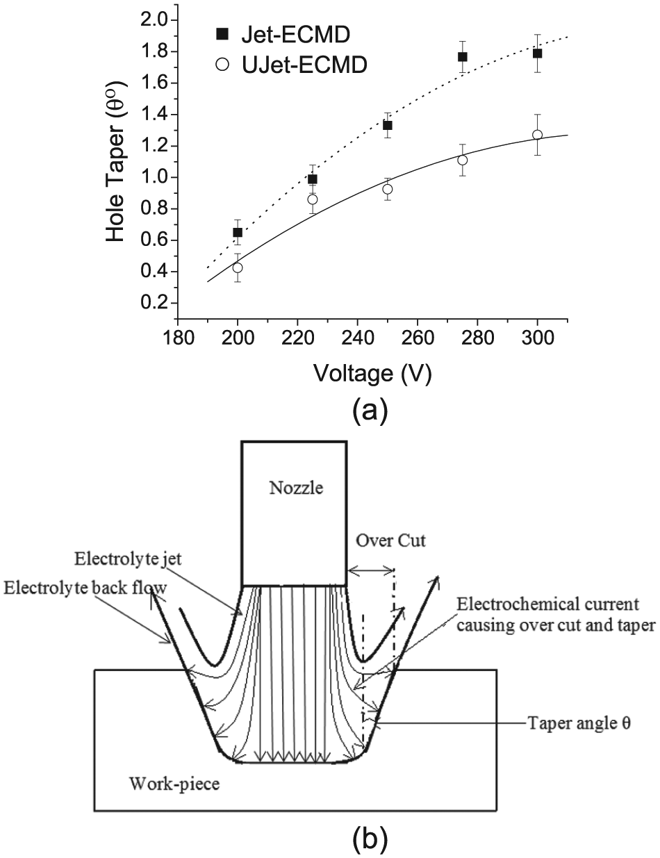
(a) Variation of hole taper with applied voltage (IEG 2.25 mm, pressure 0.13 MPa, 1M H2SO4) and (b) schematic diagram showing formation of overcut and hole taper.
With application of ultrasonic vibrations, the MRR was found to increase with significant decrease in the machining time for drilling. Due to the decrease in machining time, the interaction time of the electrolyte jet with the entry side of the hole was reduced. The side-cutting effect minimized due to the reduction in machining time. Therefore, in UJet-ECMD, the taper was less as compared to Jet-ECMD process.
Effect of electrolyte concentration
The effect of electrolyte concentration on the hole taper can be seen from Figure 11 for both Jet-ECMD and UJet-ECMD processes. It has been found that hole taper increased with the increase in electrolyte concentration for both processes. Increase in electrolyte concentration increased its ionic strength and increased the current density of the electrolyte at fixed value of voltage. The concentrated electrolyte offered less resistance to the flow of current. At higher ion content, the rate of electrochemical reactions was rapid.
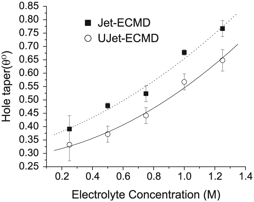
Variation of hole taper with electrolyte concentration (voltage 250 V, IEG 2.25 mm, pressure 0.13 MPa).
During Jet-ECMD, the electrolyte jet had longer contact time at the entry side of the hole during the drilling of the hole; this caused more removal of material at the entry side of the hole than the exit side. When ultrasonic vibrations were passed into the electrolyte jet due to the increase in focused agitation of ions’ MRR, the machining time was reduced significantly. The reduced machining time decreased the contact time of the electrolyte jet at the entry and exit sides of the hole that produced the holes with reduced hole taper.
Effect of electrolyte pressure
Figure 12 shows that the electrolyte pressure has also significantly affected the hole taper of the holes produced. It can be seen that the hole taper increased with increase in the electrolyte pressure for both Jet-ECMD and UJet-ECMD processes. In Jet-ECMD process, the increase in electrolyte pressure increased the electrolyte jet velocity which in turn increased the number of ions striking per unit time on the workpiece surface.
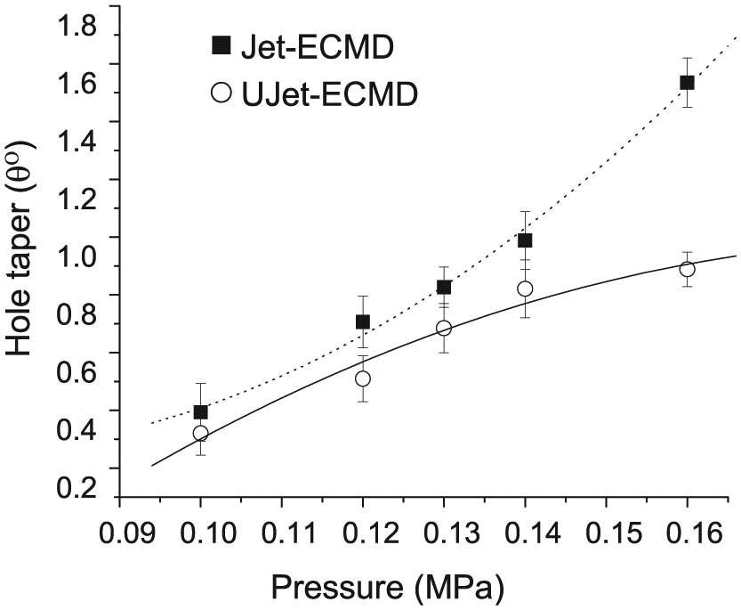
Variation of hole taper with electrolyte pressure (voltage 250 V, IEG 2.25 mm, 1M H2SO4).
The increased pressure of the electrolyte helped to flush away the hydrogen gas bubbles (which may hinder the machining process) and the heat produced during the electrochemical reactions occurring at high voltage. This allowed the flow of fresh (uncontaminated) electrolyte into the gap thus increasing the current density for the machining. Due to this, the MRR increased which also increased the hole taper produced. From Figure 12, it is clear that at the higher values of the pressure, larger taper was produced because at higher pressure the electrolyte jet was reflected backward with certain angle, as shown in Figure 7(c), after the electrolyte jet was impinged on the workpiece. Due to this, the electrolyte jet dissolved extra workpiece material from the periphery of the hole in its reversed path increasing the diameter of the hole at entry area significantly. This also affected the circularity of the hole and produced the oval holes, as shown in Figure 7(b). In UJet-ECMD, the application of ultrasonic vibrations reduced the machining time for the hole drilling which reduced the machining time of the electrochemical jet at the entry diameter of the hole, thus the hole taper was found to decrease. But in UJet-ECMD, the magnitude of hole taper was seen to be stabilizing (Figure 12) above 0.14 MPa as at and above this pressure the machining time was very less of about 20–22 s for 350 µm depth of the hole which reduced the interaction time of the electrolyte jet with the entry side of the hole considerably.
Effect of IEG
The effect of IEG on the hole taper has been shown in Figure 13. It was found that with increase in IEG, the hole taper decreased for both the Jet-ECMD and UJet-ECMD processes. With increase in IEG, current density between anode and cathode decreased due to increased resistance of the conducting electrolyte jet between the cathode and anode. This reduced the rate of electrochemical reactions and the metal removal rate. Due to reduced MRR machining at the entry diameter of the hole also reduced resulting into smaller entry diameters. Hence, the hole taper was found to decrease with the increase in IEG in Jet-ECMD. With the application of the ultrasonic vibrations, hole taper reduced further as compared to Jet-ECMD due to the reduced machining time. Reduced machining time resulted into lesser contact duration of the electrolyte jet with the entry side of the hole as well as with the lateral sides of the hole and produced less tapered holes.
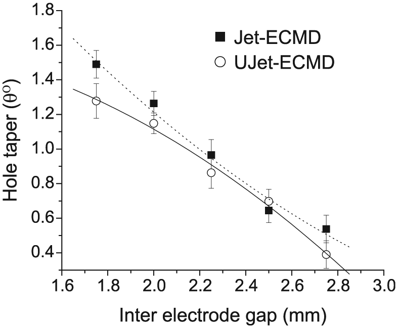
Variation of hole taper with interelectrode gap (voltage 250 V, pressure 0.13 MPa, 1M H2SO4).
Effect of pulsed DC
Graphs obtained for hole taper with respect to change in pulse on time of the pulsed DC voltage are shown in Figure 14. It can be seen that the hole taper increased with increase in pulse on time of the pulsed DC voltage. In Jet-ECMD process, increase in pulse on time increased the electrochemical reaction time as well as the machining time. Due to this, the material removal at the entry side of the hole was more with increased machining time. This increased the entry side diameter of the hole than the exit side which resulted in the increased taper. With the UJet-ECMD, the hole taper has reduced with pulse on time as compared to the Jet-ECMD as seen from Figure 14. The rate of electrochemical reactions enhanced with the effect of acoustic manipulation of the electrochemical species in the electrolyte jet, but the hole taper was found to decrease in UJet-ECMD due to the significant reduction in the machining time. The optical microscopic images of holes drilled by Jet-ECMD and UJet-ECMD as well as pulsed DC, Jet-ECMD and Pulsed DC, and UJet-ECMD processes with the experimental parameters used are shown in Figures 15–18, respectively.
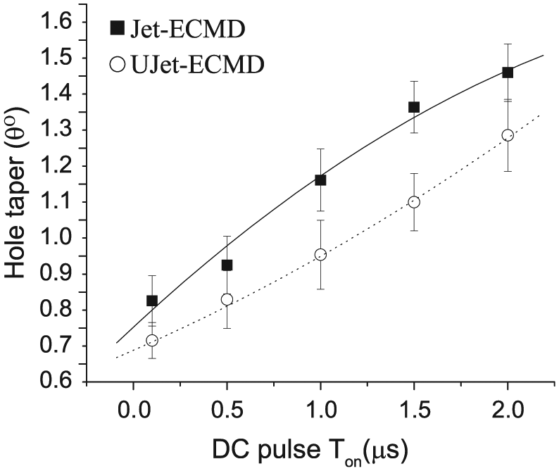
Variation of hole taper with pulse on time (pulsed DC-applied voltage) (voltage 270 V, IEG 2.25 mm, pressure 0.13 MPa, 1M H2SO4, pulse off time 3 µs).
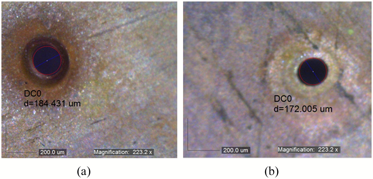
Optical images of drilled hole by Jet-ECMD (electrolyte concentration = 1M H2SO4, voltage = 250 V, IEG = 2.25 mm, pressure = 0.13 MPa, Ton ultrasonic vibrations = 0, Toff ultrasonic vibrations = 0 s): (a) entry diameter and (b) exit diameter.
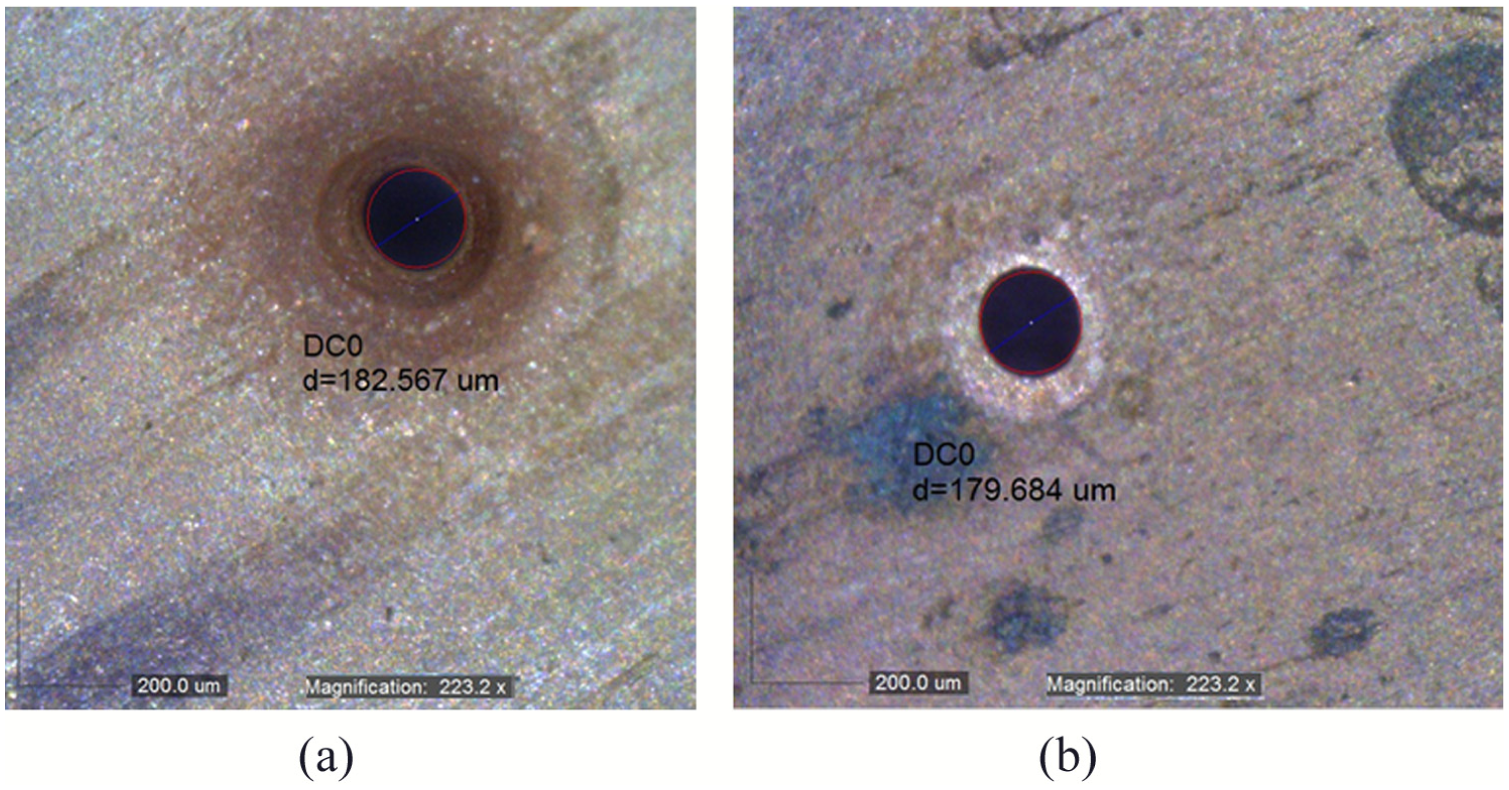
Optical images of drilled hole by UJet-ECMD (electrolyte concentration = 1M H2SO4, voltage = 250, IEG = 2.25 mm, pressure = 0.13 MPa, Ton ultrasonic vibrations = 0.5 s, Toff ultrasonic vibrations = 0.5 s): (a) entry diameter and (b) exit diameter.
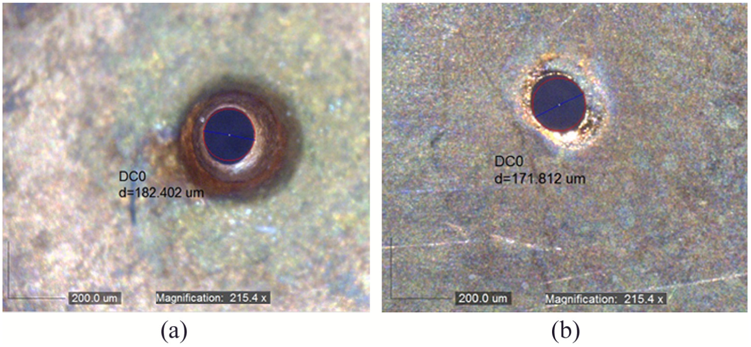
Optical images of drilled hole by pulsed DC-Jet-ECMD process (electrolyte concentration = 1M H2SO4, voltage = 270 V, IEG = 2.25 mm, pressure = 0.13 MPa, Ton DC voltage = 1.5 µs, Toff DC voltage = 3 µs, Ton ultrasonic vibrations = 0 s, Toff ultrasonic vibrations = 0 s): (a) entry diameter and (b) exit diameter.
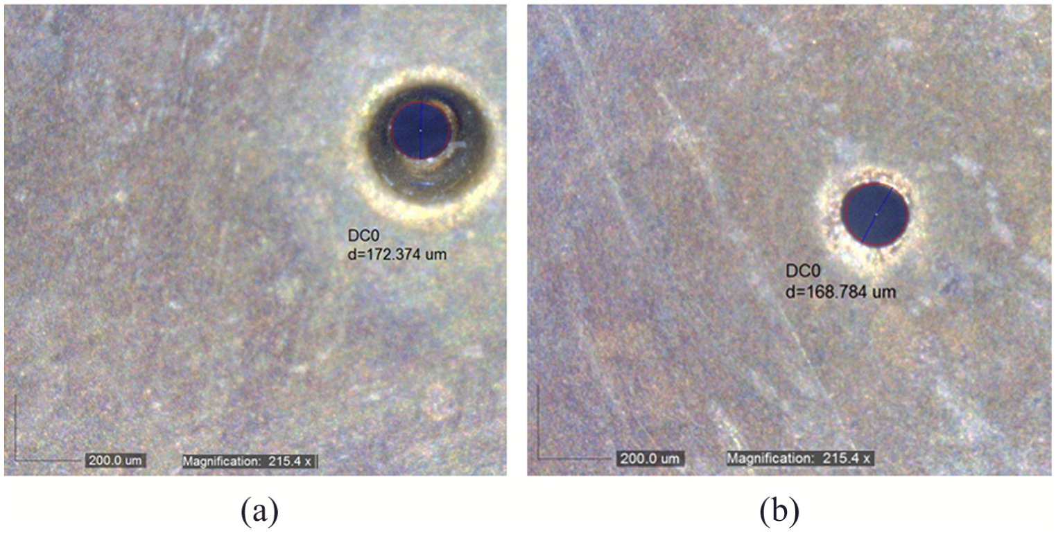
Optical images of drilled hole by pulsed DC-UJet-ECMD (electrolyte concentration = 1M H2SO4, voltage = 270 V, IEG = 2.25 mm, pressure = 0.13 MPa, Ton ultrasonic vibrations = 0.5 s, Toff ultrasonic vibrations = 0.5 s): (a) entry diameter and (b) exit diameter.
Conclusion
In this study, experimental setup for Jet-ECMD process has been designed and fabricated. The drilling of holes with electrochemical jet of 140 µm diameter has been successfully performed on the copper workpieces. Attachment for the supply of the coaxial air flow along with the electrolyte jet has been fabricated. Trial experimentation has been performed to prove the efficacy of the process with the coaxial air supply. A separate attachment has also been fabricated to induce the ultrasonic vibrations into the electrolyte jet. Experiments were conducted with Jet-ECMD and UJet-ECMD processes. Experiments were also performed with pulsed DC power supply for Jet-ECMD and UJet-ECMD processes. Critical comparison of all these variants of the Jet-ECMD process have been done to investigate the effects of various process parameters, namely, applied voltage, electrolyte concentration, electrolyte pressure, IEG on the two process responses such as MRR and hole taper. The supply of air coaxially with the electrolyte jet has been found to improve the machining conditions considerably in terms of producing holes with smaller diameters closer to the nozzle diameters due to better localization of the current density in the machining zone. The tendency of sparking between the nozzle and workpiece was found to reduce with the air assistance. The performance of the Jet-ECMD has been compared with UJet-ECMD process, and it was concluded that the UJet-ECMD has better micro-drilling abilities than the Jet-ECMD process. It was found that the application of ultrasonic vibrations has increased the MRR of the Jet-ECMD process significantly. UJet-ECMD also has the ability to produce hole with less taper than Jet-ECMD process. The effect of pulsed DC supply has been studied on the process responses such as MRR and hole taper. It was observed that pulsed DC produced better holes with UJet-ECMD than the Jet-ECMD. MRR is more in case of pulsed DC UJet-ECMD, and the taper produced was also found less in case of UJet-ECMD process when compared to the pulsed DC-Jet-ECMD process. Hence, it was concluded that the application of coaxial air and the ultrasonic assistance has improved the process performance of both Jet-ECMD and UJet-ECMD with DC and pulsed DC supply.
Footnotes
Declaration of conflicting interests
The author(s) declared no potential conflicts of interest with respect to the research, authorship, and/or publication of this article.
Funding
The author(s) disclosed receipt of the following financial support for the research, authorship, and/or publication of this article: This work was supported by the Department of Science and Technology (DST), New Delhi, India.