
Abstract
Researches show that surface with bionic structure plays an important role in improving the aerodynamic performance on aero engine parts. Belt grinding, a popular method to process titanium alloy parts such as aero-engine blade, is also found that it can be used to obtain bionic microstructure through special grinding method and parameters.
In order to explore the performance of bionic microstructure processed by belt grinding and its effects on airflow dynamics, several groups of simulation and an experiment are carried out in this paper. Firstly, the mechanism of drag reduction of bionic microstructure is discussed. It shows that the effect of drag reduction of bionic microstructure is related to protrusion height, which is related to the shape and size of the bionic microstructure. Then, three groups of typical belt grinding bionic microstructure are set up. In addition, the drag reduction values are calculated in CFD simulation. The results are analyzed and discussed. Further, to verify the airflow dynamics of drag reduction of belt grinding bionic microstructure, an experiment of aero-engine blade is carried out. Finally, the effects of airflow dynamic performance of blade with belt grinding bionic microstructure are obtained in CFD simulation. In general, the shape of wave ribs, compared to V-ribs and trapezoidal ribs, has the best performance in drag reduction. To a certain extent, the improvement of airflow dynamic performance is higher with the increasing of the size of bionic microstructure, which suggests lower feed rate and higher grinding pressure for bionic structure.
Introduction
As a key component of aero-engine, the surface quality of blades directly affects the service performance of aero-engine. With the improvement of surface processing technology, the machining quality of blade surface is getting higher and higher. However, to further improve the performance of aero-engines, researchers are studying new processing methods or surface structures. Bionic microstructure can achieve the function of drag reduction, super hydrophobicity and super hydrophilicity in some certain conditions, which has attracted much attention of researchers. Belt grinding has the characteristics of both flexible and precise processing, which is widely used in the precision processing of aero-engine parts. It can not only guarantee the precision of processed parts but also form good surface integrity compared to turning, milling, et al. In our recent studies, belt grinding can also process microstructures by taking a special processing method. However, as the grains attached to the belt is randomly distributed, it is difficult to obtain regular microstructures by normal belt grinding method. Therefore, this paper studied the airflow dynamical performance of surface with bionic and the microstructure formation of microstructures inspired from shark skin using belt grinding.
The mechanism of drag reduction of bionic microstructure has been widely studied by many researchers. Bechert, 1 Walsh 2 and Paolo 3 studied the drag reduction mechanism of ribbed structures by means of numerical analysis. It is divided into two theories: transverse drag reduction mechanism and longitudinal drag reduction mechanism. Their research laid the foundation for the research on drag reduction of bionic ribbed structures. Yu et al. 4 conducted drag reduction simulation experiments on two bionic microstructures including wedge, slice and smooth surface. The effect of drag reduction was analyzed from the perspective of thermodynamics, which is rarely used in other studies. And it is concluded that wedge model has better drag reduction effect than slice model, and that increasing wedge model Angle can improve drag reduction effect. Scholle et al. 5 analyzed the phenomenon of reduced resistance due to corrugated surface in Stokes flow. It is shown that vortexes are formed between ribbed structures distributed perpendicular to the direction of liquid flow. These vortexes act like fluid roller bearings, supporting the flow of fluid on the surface, thus reducing fluid resistance. The transverse drag reduction phenomenon analyzed in this paper is in good contrast with the longitudinal drag reduction phenomenon.
Relevant scholars have also done a lot of researches on the processing of bionic surfaces and the characteristics of bionic surfaces, and have achieved good results in reducing noise, improving hydrophobicity or improving aerodynamic performance. Buttner et al. 6 prepared the 10-nanometer bionic ribs structure of shark skin by laser processing and electrodeposition, and studied the thermal drag reduction performance of nickel-based alloy aero-engine blades coated with bionic ribs structure. The wall shear stress of the oil channel was decreased by 4.9%. The experiment showed that the surface with the bionic ribs microstructure could be applied to the blades of aero-engines, whose working environment is high temperature and pressure. Schlieter 7 fabricated the bionic ribs structure by halogenation, coating, laser ablation plus oxidation. Then systematically compared the mechanical properties of high and low cycle fatigue of the structures made by these methods. The results shown that the surface obtained by laser machining has the best comprehensive mechanical properties. Liu 8 was inspired by typical plant surfaces such as lotus leaves and rose petals. First, the surface of the workpiece was pre-processed by laser, and then the bionic surface with higher hydrophobicity and corrosion resistance was processed on the surface of magnesium alloy by chemical corrosion method. Chen et al. 9 fabricated the surface microstructures imitating the structure of shark skin. By measuring the friction coefficient and the quality of adherent tissue of the leaves with different bionic surfaces and pig liver tissues, it is proved that the bionic shark skin surface can effectively reduce the adherent tissue of the leaves. Manickam et al. 10 investigated microgrooving on crystalline germanium (Ge) <100> surface using 1064 nm wavelength ultrafast laser pulses under ambient condition. They found that the depth and width of grooves increase with laser power and groove depth and width decrease as the pulse repetition rate increases. Zhang et al. 11 studied the preparation of a bionic super-hydrophobic metal surface, using picosecond laser ablation, electro-polishing and electrodeposition techniques. The machined surface has good hydrophobic property and can maintain Cassie state steadily. Liu et al. 12 discussed the characteristics of biomimetic hydrophobic surfaces, carried out a lot of experiments to prepare biomimetic surfaces, and discussed the hydrophobicity of biomimetic structures under different parameters through simulation analysis.
Because of its elasticity and low temperature, belt grinding is widely used in precision machining of thin parts such as blade, casing. There are many researches on the processed surface by belt grinding and its effects on precision, surface roughness, residual stress and so on. Duan et al. 13 proposed a fuzzy proportional–integral–derivative control strategy based on a mathematic model of normal grinding force. The machining qualities, such as surface roughness, form accuracy and consistency, are improved significantly. The single factor belt grinding experiments of titanium alloy aero-engine blades were carried out by Chai et al. 14 The effects of belt linear speed and belt feed speed on belt blockage during grinding were analyzed. Huang and Xiao15,16 developed an adaptive abrasive belt grinding method for integral blade disk. The deformation error of blade and contact flutter was compensated by measuring and controlling contact pressure. Precision grinding was achieved by controlling rotating speed. Experiments show that the method can be used as a precision processing method for blade disk.
As for the micro grinding, because the size of the grains are at micro level, micro grinding can be achieved in some conditions to realize special surface functions. But the problem is what’s the relationship between the grinding parameters and processed structures and how to get the wanted structures. Xie et al.17,18 used diamond grinding wheel to grind out micro grooves on single crystal silicon in dry condition and found that the shape of the groove was related to the shape of diamond grains, such as the front angle of the grain, the radius of the grains tip. Ohmori et al. 19 utilized an ultra-precision micro-grinding technology using fine-diamond grinding tools whose edges have been sharpened by electrical and mechanical processes to fabricate the germanium immersion grating, and successfully obtained a sharp and smooth V-faced grating structure using germanium. Lu et al. 20 used a dual-axis grinding wheel to process the optical lens and obtain a uniform instead of directional surface texture which largely improve the surface quality of the optical lens.
It can be seen from the above analysis that the drag reduction mechanism and machining of biomimetic ribbed microstructures have attracted extensive attention. However, the processing methods of biomimetic structures are still in the stage of exploration and discovery. All kinds of new processing methods that may realize the processing of ribbed structure are the focus of researchers. As a precision machining method, belt grinding has its unique advantages for micro structure surface machining. However, at present, there is almost no research on the performance of grinding bionic microstructures with belt grinding. Therefore, it is of great significance to study the airflow dynamic performance of bionic microstructure by belt grinding for exploration of both belt grinding and bionic surface.
Bionic surface belt grinding method based on airflow dynamics
Basic theory of drag reduction of microstructure
For an object moving in the air and subjected to the action of air resistance, the resistance is mainly divided into two parts: pressure difference resistance and friction resistance. The pressure differential resistance is mainly related to the shape of the object, while the friction resistance is related to the surface state of the object. In this paper, the frictional resistance is mainly considered to discuss the aerodynamic performance.
The total resistance can be obtained by integrating the shear stress of the discrete element on the whole working face, as shown in the following formula.
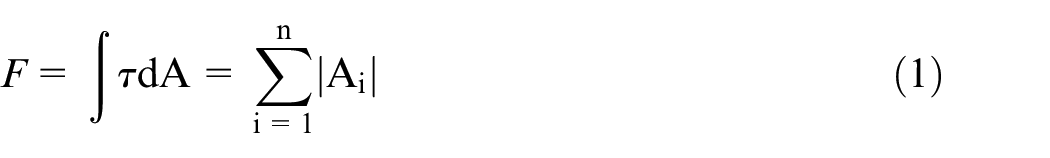
Friction stress τ, including viscous shear stress and Turbulent Reynolds Stress, is expressed as follows:
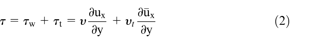
where, υ is the fluid viscosity coefficient, υt is the turbulence viscosity coefficient, ux is the instantaneous velocity, and
The flow field near the wall is called the laminar boundary layer, while the flow field far from the wall is called the turbulent layer. In the flow field near the wall, the resistance mainly comes from viscous shear stress. In the turbulent layer far from the wall, the resistance mainly comes from Reynolds shear stress. Experiments show that the velocity gradient of the flow field near the wall machined with bionic surface decreases, the thickness of the viscous layer of the boundary layer increases, and the viscous shear stress decreases correspondingly. In addition, the wall with bionic surface can make the turbulence intensity decrease rapidly in the direction of deviation from the wall to the near wall, so the Reynolds stress can also be reduced accordingly.
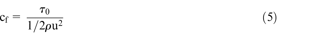
According to the theory of “Protrusion height,” 1 the drag reduction effect of bionic ribbed surface can be expressed by the following formula:
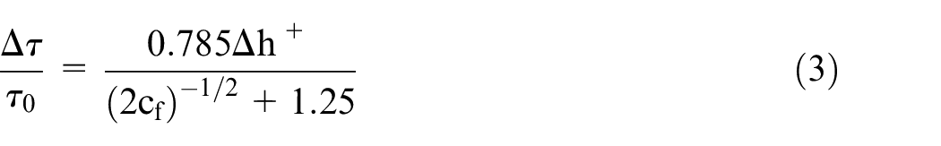
Where Δτ is the difference of the shear stresses between test plate and reference smooth plate, τ0 is the shear stress of the reference smooth plate,
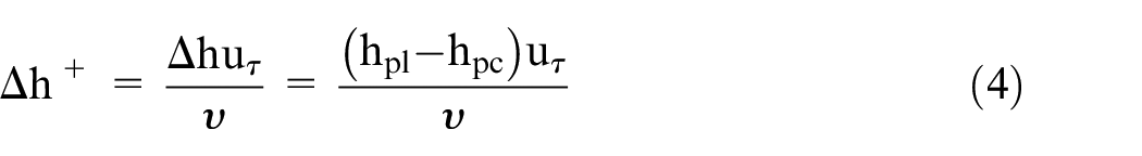
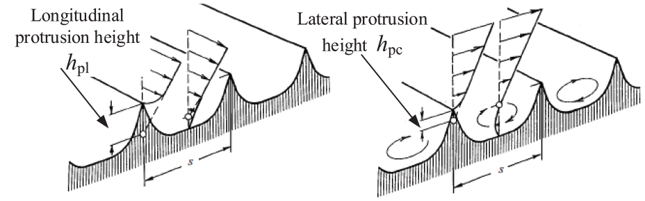
Where △h is protrusion height, hpl is the longitudinal protrusion height, hpc is the lateral protrusion height, uτ is velocity defined as uτ = (τ0/ρ)1/2, u is the average velocity and ρ is the air density.
According to the above formula, the drag reduction performance of the bionic surface airflow is related to △h and is proportional to the value of it.
Some researches about calculating the protrusion height have been done by some peer predecessors. Bechert 1 proposed a calculation method of protrusion height. The protrusion height hp is the distance between the groove tip and the equivalent smooth surface of the groove surface as shown in Figure 1. The equivalent smooth surface means that the groove surface is transformed into a flat plate through conformal transformation, so as to obtain the velocity distribution in the near-wall area of the groove surface. The velocity gradient at the bottom of the groove is the minimum, and the velocity gradient at the top of the groove is the maximum. The flow in the groove below the equivalent smooth surface is mostly blocked by viscosity. In the boundary layer flow, it is equivalent to increasing the thickness of the viscous boundary layer and reducing the average velocity gradient of the wall surface, resulting in a decrease in the surface friction resistance. The mathematical calculation process is shown in the Figure 2.
Viscous longitudinal and crossflow on a ribbed surface. 21
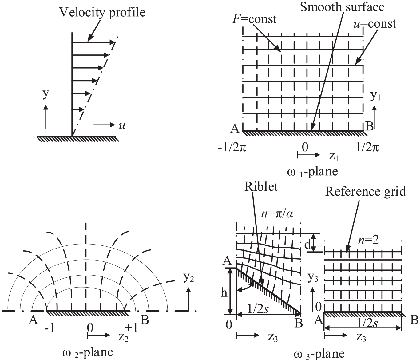
The mathematical calculation process.
Finally, through conformal transformation and Sehwarz-Christoffel mapping, the general calculation equation of hp/s is obtained.
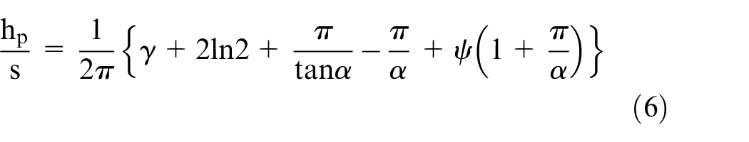
Where s is the lateral riblet spacing, γ = 0.5772 is the Euler constant and ψ is the Digamma function which is the logarithmic derivative of the Gamma function.
From the formula above, we can see the protrusion height is related to the half tip angle α. By adjusting it, drag reduction can be theoretically controlled. Therefore, in the following part, the tip angle is taken into consideration to explore the relationship between drag reduction and tip angle.
Typical bionic microstructure surface
It can be seen from the above analysis that the surface with V-shape groove is the typical structure of belt grinding bionic microstructure surface. However, in the actual grinding process, the surface of the bionic microstructure is sometimes represented as trapezoidal and wavy groove due to the use of different types of belts and wear of the abrasive grains. 21
So in this paper, three kinds of models with the bionic microstructures are set up, as shown in Figure 3.
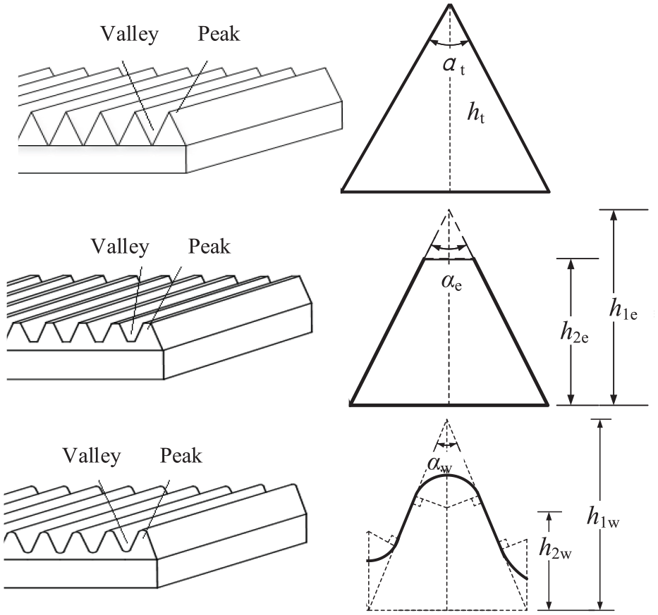
Bionic microstructures with three kinds of cross-section.
An imaginary isosceles triangle is introduced to determine the dimensions of trapezoid and wave groove. And it can be facilitated to make a comparison of the dynamic performance of the flow with different shape of grooves when they are in the same size. For example, let αt = αe = αw and ht = h1e = h1w. Then it can be ensured that the three different models have similar structure proportion with their own characteristics. By gradually changing the tip angle αt, αe and αw, we can obtain different structures based on the three structures above. Thus, we can further obtain the optimized structure extracted from Bechert. 20
Simulation parameters and drag coefficient
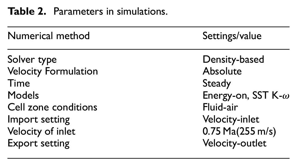
This section mainly studies the airflow dynamic performance of belt grinding surface of titanium alloy used in aerospace field. Since the working environment belongs to the high-speed environment, there must be the change of heat, so the energy equation is on. At the same time, because it is impossible for the airflow to maintain a smooth laminar flow after passing through the contact surface, the SST K-ω model in the turbulence model is adopted. Aircraft and other spacecraft are working in the earth, so the fluid flowing into the flow field is ordinary air, so the flow is set as a compressible ideal air.
In the simulation, the air only enters from the inlet surface and exits from the exhaust surface, so the boundary condition only needs to be set for the inlet surface of the air stream, namely the inlet surface. The pressure of the working environment of aerospace equipment is atmospheric pressure at the initial condition, so the pressure of the initial flow field is set to 11,111 Pa. The initial speed is set to 0.75 Mach number (about 255 m/s), referring to the aircraft’s speed. More details can be seen in Table 2.
As for the drag calculation, since we know the inlet velocity and the outlet velocity, the difference between them is the velocity loss caused by drag. So we can define the drag coefficient by:
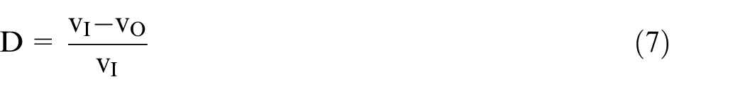
Where vI is the velocity of inlet and vO is the velocity of outlet.
Simulation for drag reduction of typical bionic microstructure
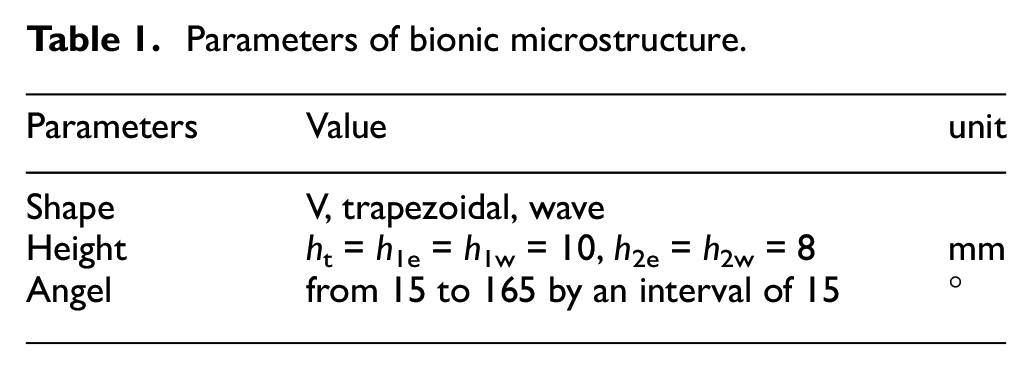
The size of the models used in simulation are shown in Table 1 below. The samples angles of each model increase from 15° to 165° by an interval of 15°. Thus, there are 33 samples to calculate in total.
Parameters of bionic microstructure.
The boards with bionic microstructure are imported into ANSYS Fluent to analyze the aerodynamic performance. The calculation parameters are set as shown in Table 2 below. And the compute region is shown in Figure 4.
Parameters in simulations.
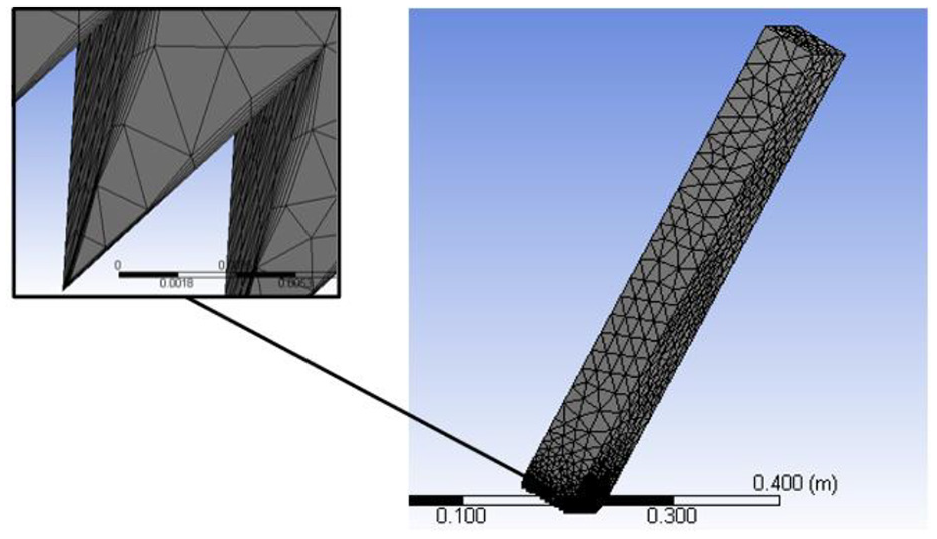
Mesh of compute region.
In order to avoid the interference of upper and lower flow fields, the height of the computational field should be large enough. The upper wall and the left and right walls are smooth while the lower wall is in groove structure. The front and rear walls are defined as the inlet and outlet of the fluid. Some of the simulation results are shown in Figure 5.
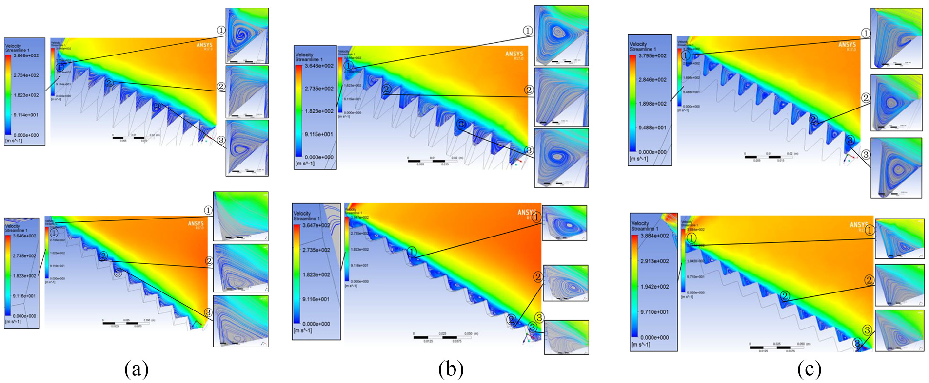
Simulation of airflow on the surfaces with bionic microstructure. (a) A velocity flow diagram of a V-shaped ribbed surface. (b) A velocity flow diagram of a trapezoidal ribbed surface. (c) A velocity flow diagram of a wavy ribbed surface.
After setting the same simulation environment, the velocity of outlet are compared among those different models. So the effects of drag reduction can be easily obtained. The results are shown in Figure 6.
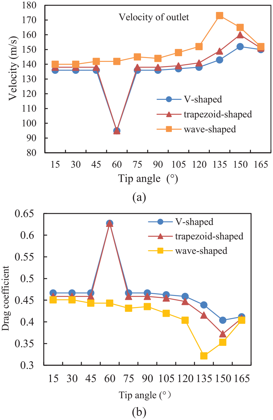
(a) Comparison of velocity of outlet; (b) drag coefficient of three structures with different tip angle.
Based on the results of the average output velocity and drag of each model with different angles, conclusions are obtained as follows. The three shapes have the same trend with the angle increase, excluding when the angle is 60°. When the V-shaped surface and the trapezoidal surface are at the same tip angle, the dynamic performance of the airflow is almost the same. But the aerodynamic performance of the surface of wavy surface is generally better than that of both V-groove and trapezoidal groove, because the drag coefficient is smaller than both. For further, the groove with an angle of 60° should be avoided as far as possible. Because from the Figure 5, we can see a sharp decrease of outlet velocity is obtain for both V-shape and trapezoid shape, which means a large loss in velocity caused by drag. When the surface of wavy groove is to be selected, the structure with the top angle of about 135° should be chosen, while the angle that is too large or too small is not suitable.
Experiment of bionic microstructure surface with belt grinding
Bionic microstructure processing with belt grinding
The protrusion height of the bionic structure surface is related to the geometric parameters of the bionic ribbed surface. And the processing parameters directly affect the geometric parameters of bionic surfaces. In our previous study, the model of bionic microstructure with belt grinding has been set up as follow. 22
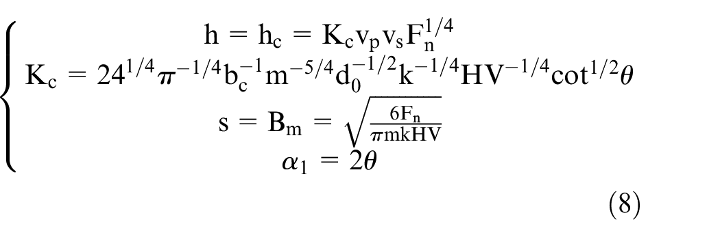
Where hc is the maximum cutting depth for single abrasive, Kc is the cutting depth coefficient of single particle, Fn is the normal cutting pressure, vp and vs are the feed speed and belt line peed of grinding process, m is the abrasive grain density, 2θ is the cone angel of abrasive grain, k is the action coefficient between workpiece and grain, bc and d0 are the width and diameter of contact wheel, HV is the hardness of contact wheel. Some symbols are shown in Figure 7. 22
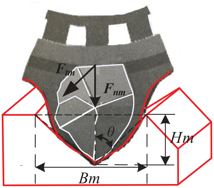
Single particle model for abrasive belt grinding.
In the grinding process, a very small belt line speed is adopted to grind the parts. As for conventional belt grinding, the normal feed is continuous to guarantee the processed surface grinding enough times. But for bionic surface belt grinding, the normal feed is discontinuous. The grinding head will raise after grinding one section of the surface, and then move to the next section and lay the grinding head down to continue grinding. At the beginning of the experiment, the grinding head and workpiece are installed on the belt grinding machine. The angle between the grinding head and the extension direction of the designed rib lines of the part is set in advance. In this experiment, the surface of the workpiece is ground in the 90° angle direction. Then the machine tool will control the grinding head to get close to the processing surface. When grinding head reaches the designed distance from the workpiece, the spindle accurately controls the speed of the belt, and the belt rotates and moves along the designed angle to complete the bionic surface processing of one stroke. Then lift the grinding head and adjust the position to the next position. Do the action repeatedly until all required processing surfaces are finished.
Experimental equipment and materials
To explore the performance of bionic microstructure of belt grinding for titanium alloy in aero-engine, a bionic microstructure belt grinding experiment is carried out.
The experiment was carried out on the seven-axis Six-linkage self-adaptive CNC belt grinding machine tool of Chongqing Sam Hida Grinding Machine Co., Ltd. Its structure is shown in Figure 8. The free-form surface grinding head is controlled by high-grade CNC system. The processed parts are clamped on the A-axis tooling. The precision belt grinding head is installed on the grinding head rack which can rotate around two axes (B, C axis) and move along two coordinates (Y, Z). The machine can automatically grind, finish and polish the free-form surface. In addition, the grinding pressure is controlled by servo motor in real time, which can adjust the machining allowance of the workpiece to achieve.accurate material removal.
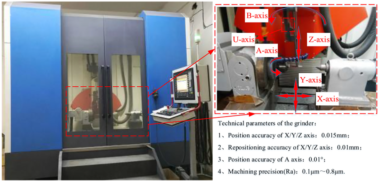
MGY5540A-7NC CNC belt grinding machine.
Titanium alloy is a kind of difficult-to-process material. So it is important to select suitable belt to guarantee the grinding quality and processing consistency. Diamond abrasive belt has the characteristics of high grinding efficiency, durability, smoothness, glossiness and cost-effective. It is suitable for grinding difficult-to-machine materials such as titanium alloy and keeps low abrasive wear rate during grinding. It can avoid the influence of abrasive belt wear on the surface quality during the experiment. Therefore, diamond abrasive belt is chosen as grinding belt in this experiment. The width of the belt is 5 mm and the particle size is P200.
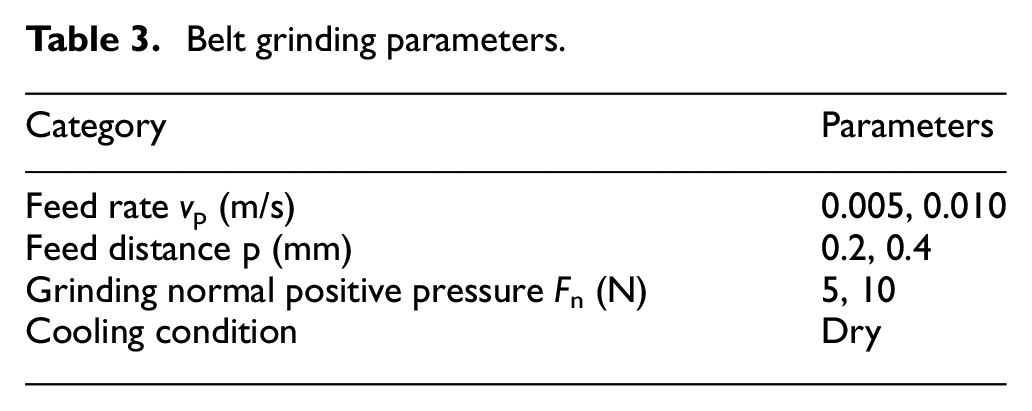
Single factor experiments were carried out with different grinding speed and feed rate, which were divided into eight groups. The grinding parameters are shown in Table 3 below. Eight groups of process schemes were used to grind a section of the board for further data detection.
Belt grinding parameters.
Detection of ground surface
The machined surface was inspected by ultra-depth-of-field electron microscopy to inspect the surface quality of the ground surface from the microscopic view. The results show that the belt rows out the grooves on the surface of the blade, and the grooves evenly distribute on the surface. The width of the bionic ribs varies from 20 to 40 μm, while the height varies from 3 to 10 μm. And the angle of the ribs is about 120°. The bionic structure is more obvious when the surface is ground with smaller belt speed and smaller grinding feed speed.
In order to study the airflow dynamic characteristics of the machined bionic surfaces, two kinds of surfaces were selected to fit the surface geometric model for simulation. Both of the selected surfaces have the wave ribs. The ribs on the first one surface has a bigger size (vp = 0.005 m/s, p = 0.4 mm, Fn = 10 N) while the another one has a smaller size (vp = 0.01 m/s, p = 0.2 mm, Fn =5 N). The surface morphology and their section size of model are shown in Figure 9.
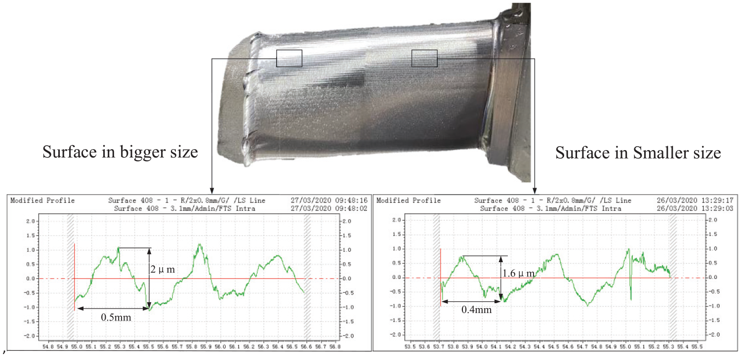
Two kinds of ribbed surface by different parameters.
Analysis of aerodynamic performance on working surfaces of aero engine
In order to explore the performance of the bionic surface on the free-form surface, the aerodynamic performance of the bionic structure on the free-form surface is also simulated and analyzed. As shown in Figure 10, the surface is a common free-form surface in aero-engine parts. The bionic structures described above are modeled proportionally on the free surface. Then introduced into ANSYS Fluent for fluid simulation to obtain the aerodynamic performance data to further verify the improvement of aerodynamic performance of aero-engine components with bionic surfaces.
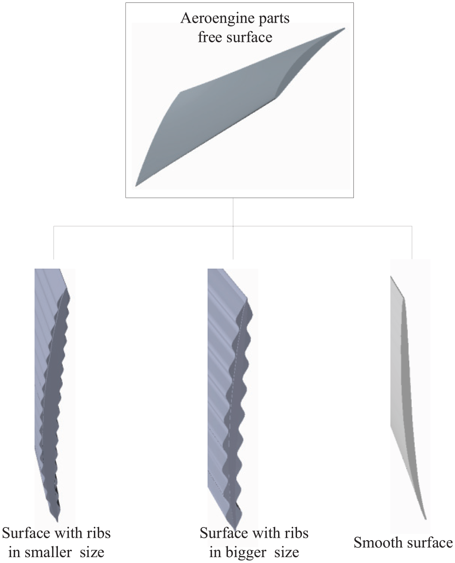
Freeform surface of aero-engine parts with bionic microstructure.
The parameters set in simulation analysis are shown in Table 3. The inlet velocity is set as 200 m/s. The velocity vector diagram of the fluid flowing through the free-form surface is obtained and shown in Figure 11.
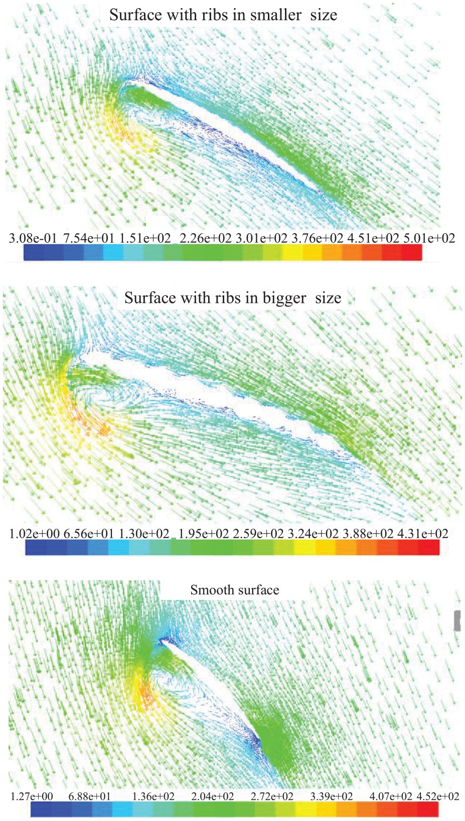
Velocity vector graph.
From the velocity vector graph, it can be seen that there are a large number of regions contain airflow with very small velocity near the surface of free-form surface with bionic structure. It shows that a layer of gas film is formed on the surface of the bionic structure, which can effectively reduce the drag of the airflow and achieve the drag reduction.
As shown in Figure 12, the velocity of a series of points along the boundary wall on convex of the blade at the same position of each simulation model are detected and compared. The tested points are uniform distributed alone the middle line of the convex. From the velocity curve, it can be seen that the velocity of points near the wall of a smooth surface are the highest, while those of a surface with a bigger bionic ribs are the lowest. It shows that the velocity gradient of the surface with bigger size bionic ribs is small in the region from the wall to the near-wall, and the thickness of the viscous boundary layer increases. The corresponding viscous shear stress near the wall also decreases as a result, which presents a better drag reduction effect. All in all, the results show that the surface with bigger bionic ribs has the best drag reduction effect, followed by the surface with smaller bionic ribs. And both of them have a certain drag reduction effect compared with the smooth surface without any bionic structure.
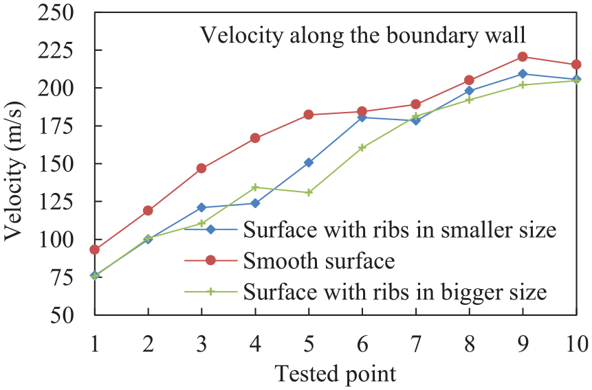
Comparison of velocities along the boundary wall.
For further, the bionic ribs in bigger size was ground by the parameters of smaller feed speed, bigger grinding normal pressure and bigger feed distance. Therefore, in the process of belt grinding, in order to obtain a bionic surface with better airflow performance, it is necessary to increase the normal positive grinding pressure, the feed distance and reduce the feed speed to a certain extent.
Conclusion
In this paper, the airflow dynamic effects of bionic surface based on belt grinding is studied. It is an important preliminary work to apply belt grinding bionic surface to industrial manufacturing, especially in the field of aero-engine manufacturing. Corresponding conclusions can be addressed as follows:
The drag reduction mechanism of ribbed structures is well discussed. It shows deeper ribs has a better drag reduction performance.
The drag performance of three typical bionic ribs with belt grinding is analyzed by CFD simulation. The surface with wave ribs has the lowest drag coefficient, thus the best drag reduction.
The belt grinding experiment of bionic surface was carried out. Smaller feed speed and bigger normal positive grinding pressure, feed distance lead to ribs in bigger size.
The blade with ribs in bigger size shows better performance on drag reduction.
Footnotes
Declaration of conflicting interests
The author(s) declared no potential conflicts of interest with respect to the research, authorship, and/or publication of this article.
Funding
The author(s) disclosed receipt of the following financial support for the research, authorship, and/or publication of this article: This work was supported by National Natural Science Foundation of China under Grant (U1908232), National Science and Technology Major Project (2017-VII-0002-0095), Graduate Scientific Research and Innovation Foundation of Chongqing, China (CYB20009), and China Postdoctoral Science Foundation (2020M673126).