
Abstract
A blisk is one of the key parts of an aero-engine, whose surface processing quality directly affects aero-engine performance. Different degrees of vibration occur during the process of new open belt grinding which seriously affect the precision of the dimensions and the surface quality of the entire blade profile. With the aim of addressing this problem, this study constructed a physical model of blisk belt grinding, analysed the low-rigidity characteristics of the grinding system, and researched the vibratory mechanism of the blisk belt grinding system based on a dynamic analysis method. In addition, the factors affecting the stability of the grinding process and the stability conditions of the grinding were considered. Then, the belt grinding process of a blade surface was simulated through a numerical method. The technological parameters were quantified for different conditions of the blisk belt grinding vibration. The optimal combination of process parameters was obtained. Finally, the optimised process parameters were validated experimentally. The research demonstrates that vibration from blisk belt grinding is related to the process parameters as follows, in the order of the greatest influence: the grinding pressure, belt velocity, feed speed, and contact wheel hardness. After optimisation, the cross-sectional profile is 0.031–0.041 mm and the surface roughness is 0.1–0.2 μm; the surface is smoother and has better consistency.
Introduction
An integral impeller is a key part of an aero-engine, whose geometric machining precision and surface quality directly influence the aero-engine performance.1,2 Due to characteristics, such as the easy deformation of the thin wall of the blade, the existence of a long and narrow channel between the blades, the free surface profile of the blade, and the difficulty in processing the material (Ti-6-4), the precise machining of a blisk-blade surface has perpetually been a key problem in aerospace manufacturing. Abrasive belt grinding technology is considered to be an ideal processing method for titanium alloy parts because of its high efficiency, high precision, flexibility, and propensity for cold grinding. 3 At present, the precise machining of a blisk surface is primarily achieved through manual grinding; moreover, to improve the processing efficiency and quality, sand belt grinding technology is combined using multi-axis computer numerical control machine tools. 4 However, limited by the spatial structure of the blisk and the characteristics of belt grinding technology, the grinding head of the machine tool can only utilise the structural form of a slender rod and a small contact wheel. Thus, particularly, low-rigidity processing conditions produce a thin-walled blade, slender grinding head contact, and flexible small contact wheel. It was determined experimentally that a different vibration phenomenon occurs in the belt grinding of the blisk blade, which has a negative influence on the precision of the dimensions, surface integrity, and consistency of the blade profile.
The grinding of the sand belt on the profile of the blades of a blisk is affected by the processing of thin-walled parts; moreover, numerous scholars have studied the vibrational stability of manufactured thin-walled parts. Barnett et al. 5 uniquely determined the importance of needle geometry in minimising cutting force in needle vibration tissue cutting, and new information was found by performing needle cutting experiments with five varying conical tipped needles being inserted into ex vivo bovine liver as well as a polyurethane sheet at varying vibratory amplitudes and frequencies. Flime and Dupláková 6 introduced that the determination of the optimal exposition period through transmitted vibration from the tools and machines to the hands of the workers is possible according to a set of representative tables or graphic instruments. Biermann et al. 7 proposed a simulation method for predicting the regenerative vibration of the workpiece during milling to solve the problems of flutter occurring through the milling of thin-walled structural parts of five-axis machine tools, from which a real-time simulation analysis of the dynamic characteristics of the workpieces during the machining process was performed using a finite element method. The authors also verified the feasibility of the simulation method experimentally. Kersting et al. 8 designed a test modal analysis and measurement device for thin-walled parts, in which the dynamic characteristics of the workpiece can be measured effectively by connecting a laser measurement device to the spindle of the machine tool. Ma et al. 9 presented a novel design of an inclined feeder with a chute that vibrates like a simple pendulum, and the numerical integration programmes were developed to investigate the kinematic characteristics of the feeder. Yang et al. 10 analysed the dynamic mechanical model using Lagrange equations to obtain angular displacement equations of higher level partial block, and then the instantaneous vibration intensity and amplitude were also found.
Vibration that occurs during the belt grinding of a blisk blade is not simple to study through an experimental testing apparatus; therefore, theoretical modelling and numerical simulations are used during the grinding process, where modelling refers to the abstract description of the relationship between the physical quantities during the grinding process based on cognition and the simulation method uses the above models to simulate the grinding process. The ultimate goals of modelling and simulation are to predict the grinding results, optimise the grinding conditions, and control the grinding process. The modelling of the grinding process primarily includes three methods: empirical, theoretical, and numerical simulation modelling.
Scholars have conducted a significant amount of research on numerical simulations of the grinding process, primarily including the grinding wheel topography and workpiece morphology, the grinding law of a single abrasive particle, and the thermal stress resulting from grinding. Aurich et al. 11 established a three-dimensional (3D) landform of a grinding wheel through actual measurements of a randomly arranged grinding wheel; they obtained the shape and dynamic grinding force of the workpiece after grinding according to the geometric motion simulation. Setti et al. 12 analysed the roughness factor from the grinding temperature and the heat partition ratio point of view and expressed so that without experimental work, prediction of the roughness factor can be done, and then a new factor called the thermal factor has been proposed based on the roughness factor modifications. Komanduri et al. 13 used a molecular dynamic method to conduct a two-dimensional (2D) grinding simulation of a single abrasive particle. The difference between these studies is that the former group simplifies the abrasive particle into a cone, whereas the latter group views the sharp angle of the grinding grain as circular. Hänel et al. 14 developed a new grinding wheel base body of carbon-fibre-reinforced plastic (CFRP) to achieve grinding wheel speeds up to 150 m/s in plunge-cut centreless grinding of hardened shafts, and the grinding forces and the surface quality of different grinding tools were detected. Jourani et al. studied the influence of the shape of an abrasive particle on the friction coefficient and wear rate during abrasive belt grinding. A 3D model of abrasive wear based on the multi-roughness value of a real rough surface was used to analyse the influence of the local geometric shape of the abrasive particles on the friction coefficient and wear rate. 15 Lin et al. 16 analysed the waviness error of large axisymmetric aspheric lenses for X-axis direction as well as Z-axis direction by employing grate parallel grinding method, and the grinding wheel vibration and Z-axis interpolation pace are regarded as the main causes of the surface waviness error. Warnecke and Barth 17 used the finite element method to optimise the dynamic characteristics of grinding wheels during the grinding of hard and brittle materials. The deformation of the grinding wheel during grinding, the wear morphology of the grinding wheel under different technological conditions, the morphology of the workpiece after processing, and the grinding vibration of the workpiece were studied.18,19
The above descriptions indicate that the current studies primarily focused on the law of grinding wheel chatter, the quality of the grinding belt used for titanium alloy parts, and the material removal law, all of which remain in the primary research stage. The vibration and inhibition mechanism of belt grinding under three low-rigidity conditions of an entire impeller and the stability conditions of sand belt grinding have yet to be thoroughly studied by experts or scholars.
Low-rigidity characteristics of blisk belt grinding system
Defining tripartite low rigidity
Due to the narrow passageway between the blades of a full disk, it is difficult to design a fixture to balance the positive grinding pressure; thus, the workpiece bents and deforms under such pressure, easily causing an inconsistent amount of final material removal between the proximal and distal ends. This forms the first significantly low-rigidity condition of the grinding system, namely, the low rigidity of the grinding parts, as shown in Figure 1.
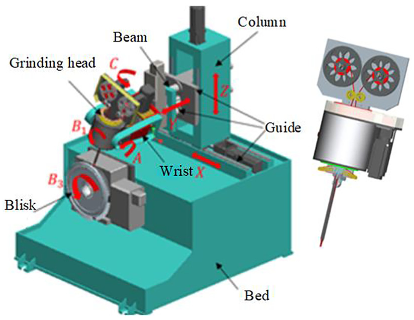
Tripartite low rigidity of blisk belt grinding.
To insert the contact wheel into the blade of a narrow integral impeller, the grinding head contact rod is formed into a slender, rectangular, cross-sectional rod structure, which itself possesses low rigidity in its thickness direction. Moreover, due to head stress points that occur during contact with the grinding wheel, both the front end of the contact rod and the smaller contact angle between the stem and leaf type surface during the grinding process (
Vibration analysis of tripartite low rigidity
In addition, for the sake of a complex curved surface fitting, a hyper-elastic material for the contact wheel can be selected, such as nitrile butadiene rubber, whose range of hardness is 35–75 Hs/A, under the action of different grinding contact forces, and can undergo elastic deformation to varying degrees. Thus, this forms the third significantly low-rigidity condition in the grinding system, namely, low rigidity in the contact between the tool and the workpiece.
The abrasive belt grinding process of a blisk-blade profile is as follows. The head contact lever and workpiece surface are ground into a constant angle,
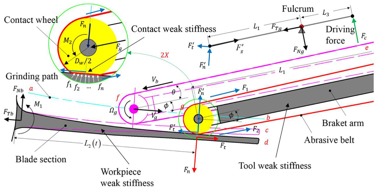
Static model of belt grinding for blisk-blade profile.
For a blisk blade, the positive pressure exerted by the grinding head along its outline in the normal direction results in a downward bending moment,
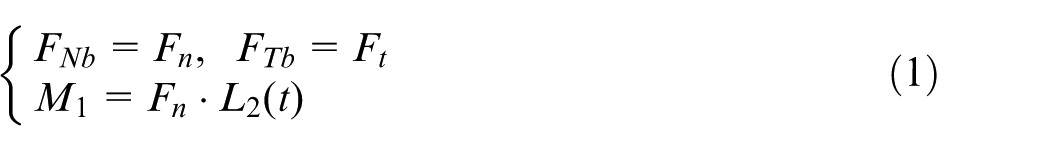
At this point,
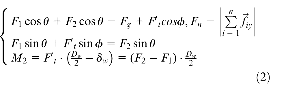
As shown in Figure 2, the positive grinding pressure, A, on the blisk blade is exerted by the cylinder through the lever principle and the contact rod is balanced by cylinder thrust,
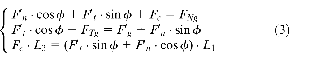
The static model indicates that contact pressure can be changed through
During this grinding process, the equivalent stiffness of the contact rod and the blade is
Finite element analysis of tripartite low rigidity of abrasive belt grinding of blisk
Finite element analysis
Single-blade blisk and contact wheel models are directly imported using CATIA after modelling. The blade, contact wheel, and contact wheel axis are then meshed. Because the material of the contact wheel is rubber, which is incompressible, a common unit, which is unable to simulate the response of an incompressible material, cannot be used; therefore, the unit type for the contact wheel selected is C3D8RH. The unit type of the contact wheel shaft and blade selected is C3D8R, and the grid is divided according to the hexahedral sweep method, as shown in Figure 3. The model has a total of 54,842 nodes and 44,927 units, including 26,627 C3D8R units and 18,300 C3D8RH units.
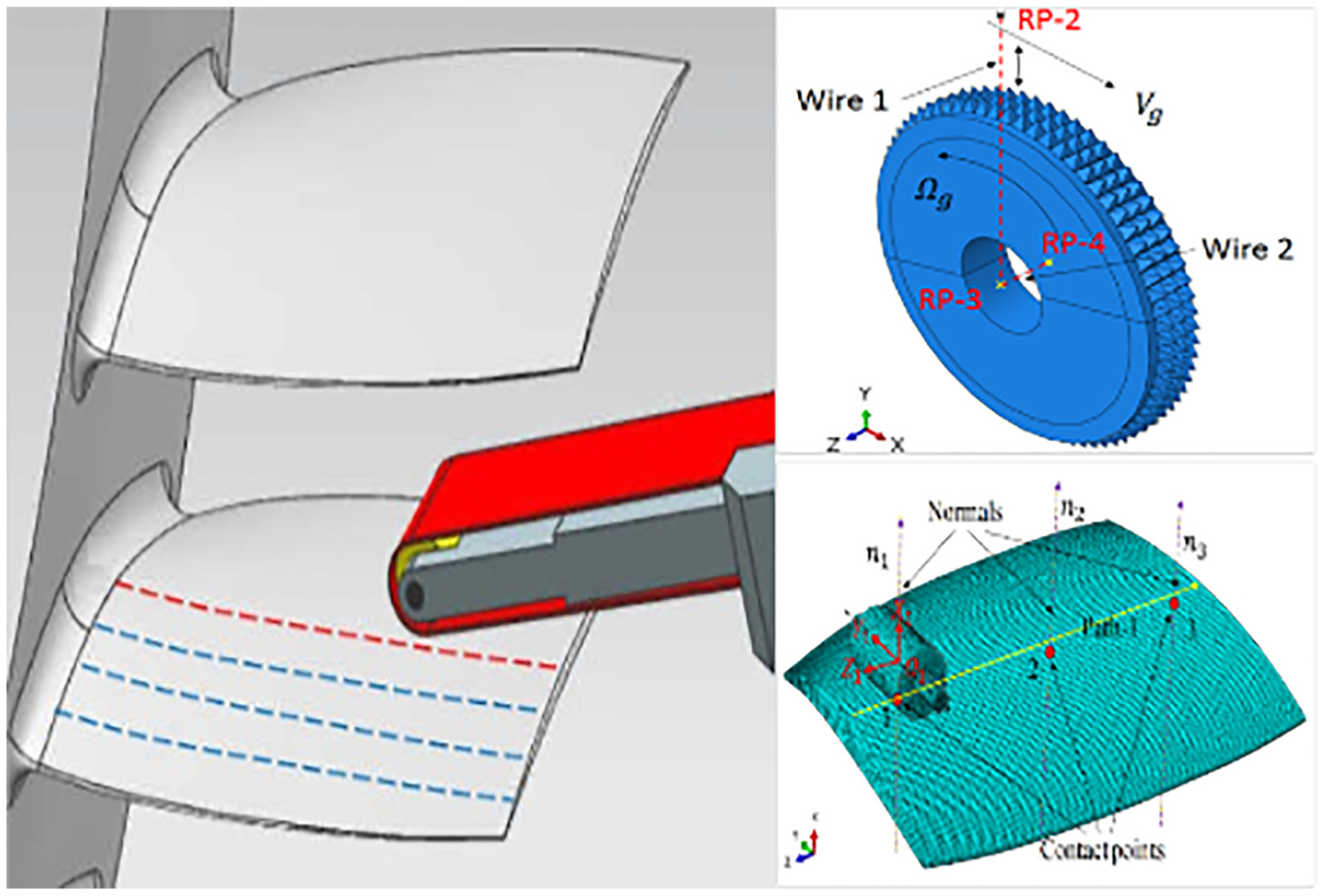
Simulation model of abrasive belt grinding for blisk blade.
The contact wheel has a plane motion, which consists of its own rotation, translation along the length of the workpiece, and vibration along the Y-axis. Therefore, it is necessary to set up two connector units to represent the low rigidity of the contact wheel rotation and the contact rod. First, two connector segments, wire 1 and wire 2, are generated based on three reference points (rp-2, rp-3, and rp-3). Then, defining the section attribute, a translator is selected for the wire 1 type, which provides the spring a damping attribute, whereas for wire 2, a hinge type is selected. Finally, the section attribute is assigned to the line segment to complete the connector definition.
A displacement cloud map of the entire model at six different contact positions was constructed. As shown in Figure 4, the deformation of the contact wheel is greater than that of the blade during the grinding process of the blade profile of the entire disk. The blade deformation is very small when the root of the blade profile is ground; moreover, the more the blade profile tip is ground, the larger the blade deformation.
Deformation nephogram of the contact model: (a) contact 1, (b) contact 2, (c) contact 3, (d) contact 4, (e) contact 5, and (f) contact 6.
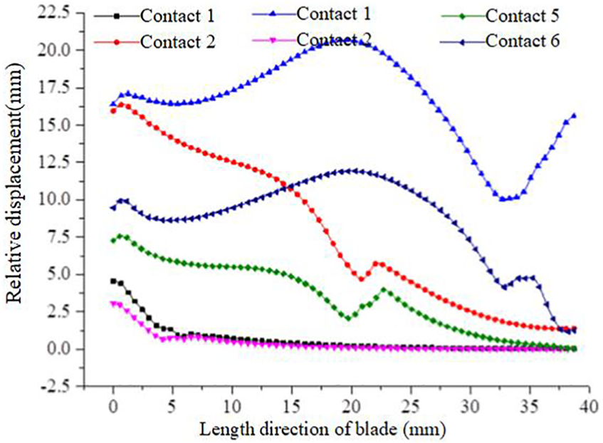
Figure 5 shows the node displacement of the blade along paths 1 and 2 at the six different contact positions. Figure 5 demonstrates that when grinding the root of the blade profile surface, a slight deformation of the blade occurs. While grinding along the path to the blade tip, the deformation of the blade gradually increases. The maximum deformation of the path node at the tip is 0.11629 mm. When grinding the back of the blade, the deformation of the basin and the root tip is smaller than that which occurs during grinding of the leaf; however, there is a significant difference between the deformation at the middle and tip of the grinding blade of 0.01559 mm at its maximum.
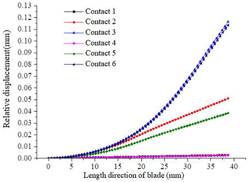
Path node displacement of blade.
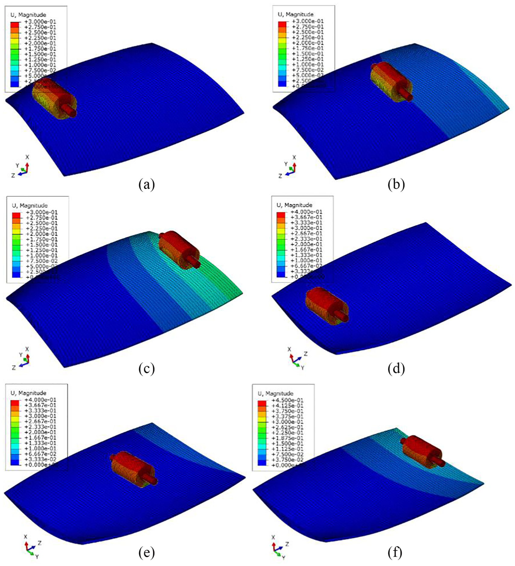
Figure 6 shows an equivalent stress cloud diagram of the entire model at six different contact positions. The figure indicates that the maximum stress of the blade increases gradually from the root to the tip. The maximum stress of the blade during the grinding of the back side occurs at the blade root and the middle of the blade’s back profile, whereas the maximum stress of the blade during the basin grinding occurs at the blade root and the inlet and outlet edges.
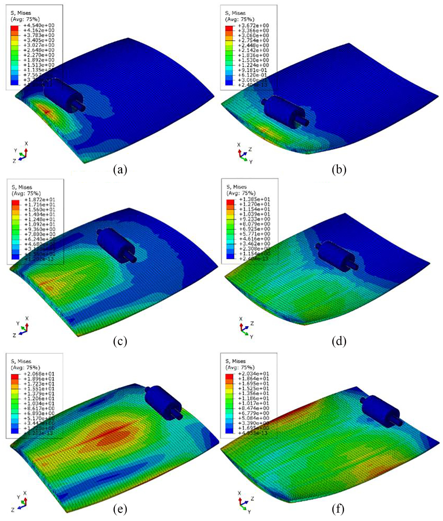
Stress nephogram of the contact model: (a) contact 1, (b) contact 2, (c) contact 3, (d) contact 4, (e) contact 5, and (f) contact 6.
Figure 7 shows the equivalent stress of nodes along paths 1 and 2 of the leaves at six different contact positions. As shown in Figure 7, the overall stress of the blade during the grinding of the blade is smaller than that of the grinding of the reverse side of the blade. At the same time, in the effective contact area, the stress of the blade clearly decreases, which indicates that abrasive belt grinding can improve the static contact stress of the workpiece. When grinding the root and central part of the blade surface, the stress along the length of the blade decreases; when grinding the surface tip, the stress on the leaf along the length direction increases after an initial decrease. The maximum stress appears at the central part of blade, which is caused by the structural shape of the blade. During the process of grinding the blade profile, the maximum stress of the blade occurs when grinding the tip which is 10.0623 MPa.
Node stress distribution of blisk blade.
Analysis of influencing factors
In this article, the standard deviation of the grinding reaction force in the Y-direction of the workpiece is used to measure the grinding stability. The average value of the grinding positive pressure is,
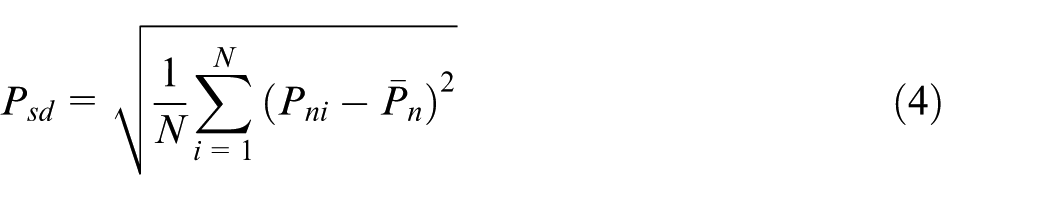
The larger the
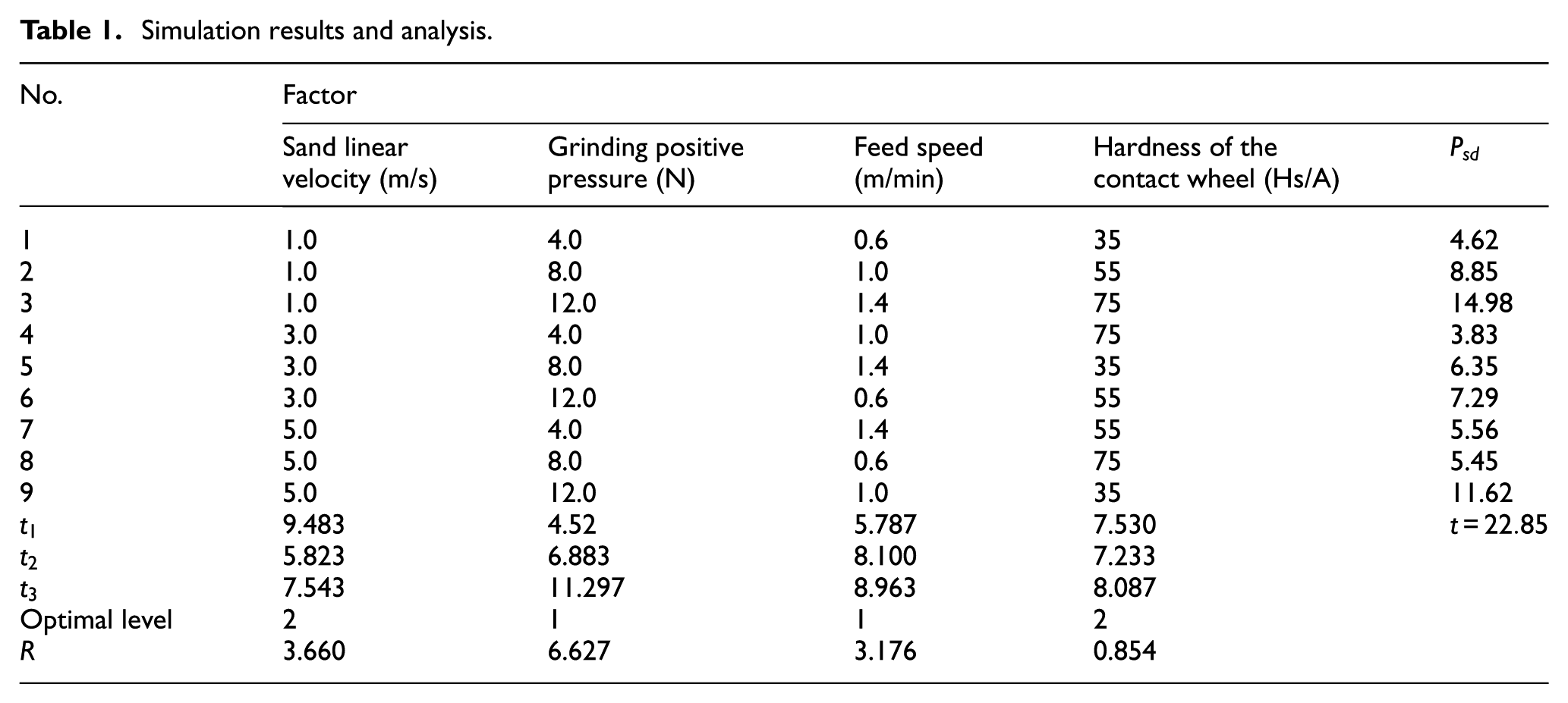
Simulation results and analysis.
In the table,
With the factor level as the abscissa, the average value of the test indicators as the vertical axis, drawing factors, and indicators of the trend are shown in Figure 8. It can be seen from the figure that the grinding stability increases first and then decreases with the increase in the sand linear velocity. The grinding stability decreases with the increase in the grinding pressure. The grinding stability decreases with the increase in the feed speed. The grinding stability increases first and then decreases with the increase in the contact wheel hardness.
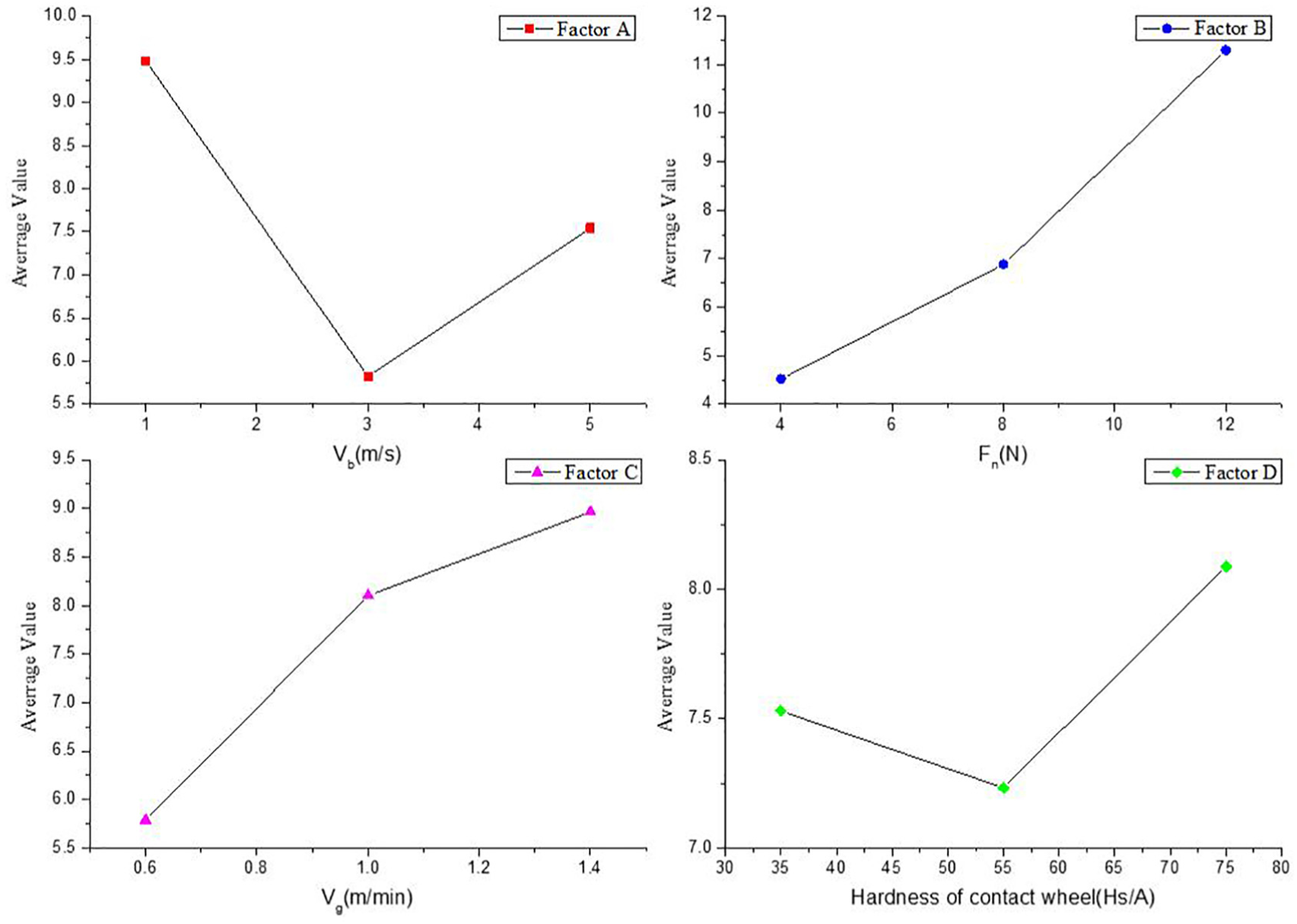
Factors and indicator trends.
Here, R is the range, which is the difference between the maximum and the minimum values of the test index for each factor

R reflects the change in the range of tested indicators when the level of each factor changes. When R is bigger, the effect of this factor on the test index is bigger, so it is more important. From Table 1, we get the order of the influencing factors as follows, in the order of the greatest influence: the grinding pressure, belt velocity, feed speed, and contact wheel hardness.
Through the best level and primary order, we get the best level combination, namely, the best combination. The optimal combination of the studied objects in this article is A2B1C1D2. And the stability of the grinding process and its indicators are obtained: the sand linear velocity is 3 m/s and its indicator is 5.823, the grinding positive pressure is 4 N and its indicator is 4.52, the feed speed is 0.6 m/min and its indicator is 5.787, and the hardness of the contact wheel is 55 Hs/A and its indicator is 7.233.
Verification experiment on belt grinding process of blisk blade
Experimental equipment and programmes
The belt grinding experiment developed for a blisk blade was performed on a self-developed experimental prototype. The blisk blade of an aero-engine compressor provided by an airline was selected as the grinding target, as shown in Figure 9.
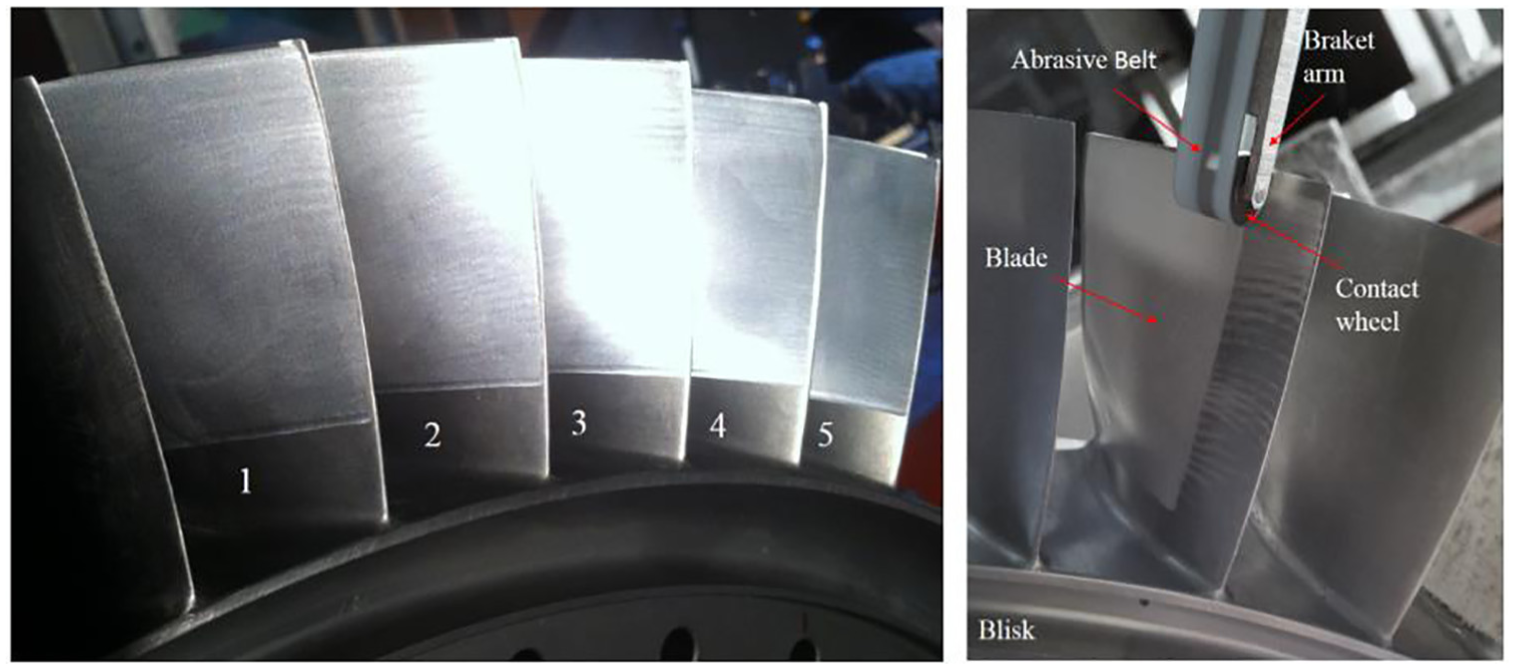
Abrasive belt grinding experiment of blisk blade.
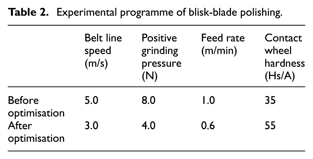
As shown in Table 2, the process parameters before and after the process optimisation were used as the experimental scheme. Using the longitudinal grinding method, five sets of grinding experiments were performed on the five blades of an entire blade disk. In this experiment, a TR200 roughness instrument manufactured by the Beijing Times Group was used to determine the roughness parameter, Ra. A three-coordinate measuring instrument, produced by Hexagon, suitable for the detection of the shape of an entire blade was used to detect the profile accuracy of the blade after grinding.
Experimental programme of blisk-blade polishing.
Vibration analysis
An analysis of the above test results is shown in Figure 10. (1) When the speed of the belt line increases, the grinding stability limit increases. (2) When the feed speed increases, the limit of the grinding stability decreases. (3) When the contact stiffness increases, the grinding stability limit decreases. Because the contact stiffness coefficient is positively correlated with the positive pressure of the grinding, when the positive pressure of the grinding increases, the grinding stability decreases. (4) When the rigidity of the contact wheel of the grinding head increases, that is, the rubber hardness of the contact wheel increases, the limit of the grinding stability increases initially, and then decreases. (5) When the equivalent rigidity of the contact head of the grinding head is increased, the limit of the grinding stability is improved, that is, when the bending rigidity of the contact head of the grinding head is increased, the limit of the grinding stability is improved.
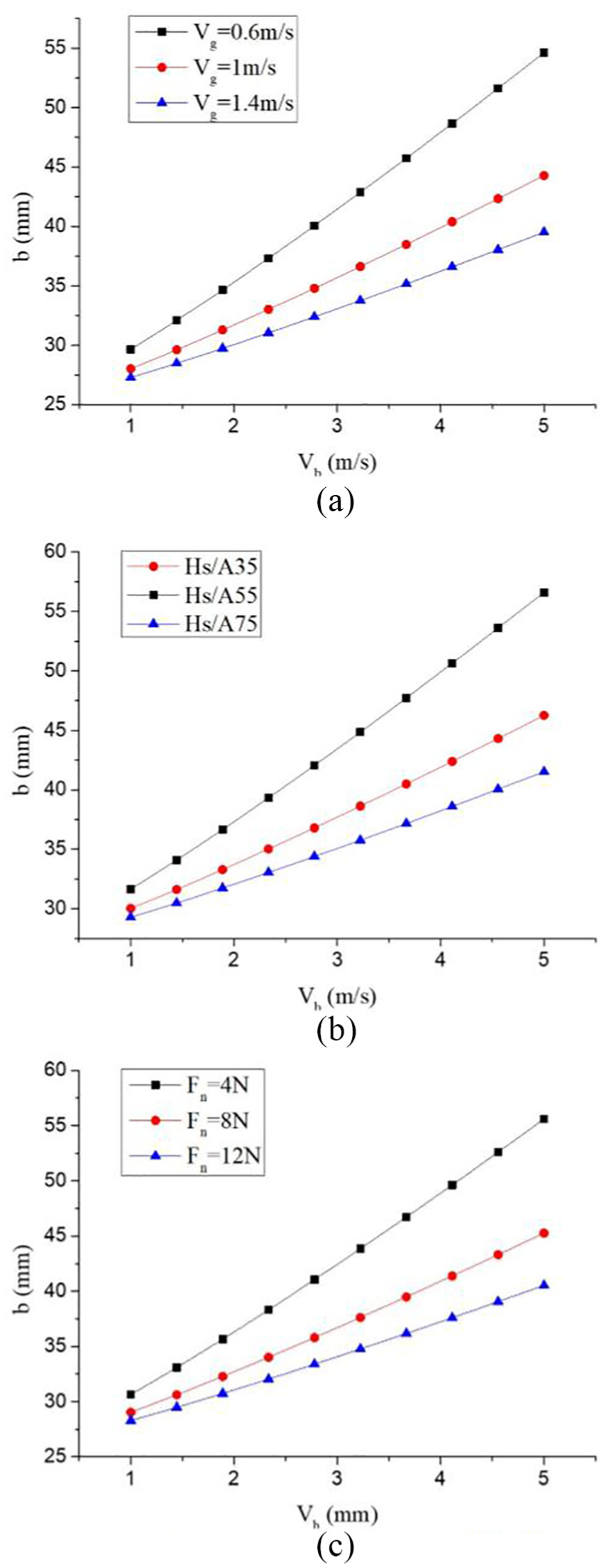
Unconditional stability boundary: (a) feed speed and stability limit, (b) contact wheel hardness and stability limit, and (c) grinding positive pressure and stability limit.
Analysis of detection results of blade profile accuracy before and after optimisation
As discussed in the ‘Introduction’ section, the overall blisk blade is used on aero-engines and requires accurate surface grinding. This experiment used a special coordinate measuring instrument produced by Hexagon to measure the precision of the entire blade surface. The three-coordinate measuring instrument was used to measure the profile of the blade before and after grinding, as well as the geometrical shape and accuracy of the profiles of the two blades, A and B, were measured. Figure 11 shows the accuracy profile of the blade profile before and after optimisation.
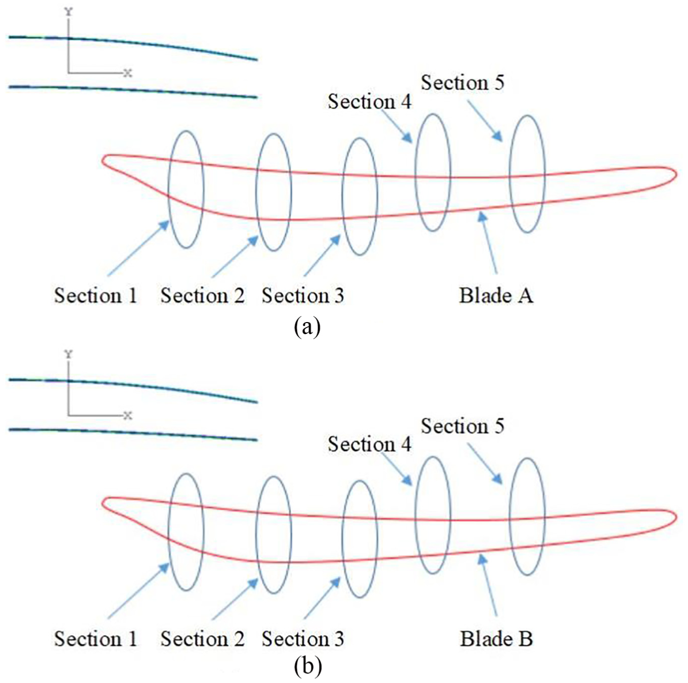
Profile error after process optimisation: (a) accuracy of blade A profile and (b) accuracy of blade B profile.
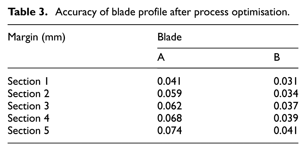
From Table 3, the trend in sections 1 to 5 indicates that the accuracy error of the profile after the grinding of the two blades generally increases. This is due to the fact that the grinding stiffness is slightly reduced from section 1 to section 5 during the grinding process; thus, the linear accuracy error gradually increases. The profile contour margin of the blade A sections is between 0.041 and 0.074 mm. Fluttering that occurs during the grinding process of the blade A surface results in less than the required surface precision of blade A. After optimisation, the cross-sectional profile of blade B after grinding is 0.031 to 0.041 mm, which satisfies the profile accuracy requirement of −0.03 to + 0.05 mm.
Accuracy of blade profile after process optimisation.
Analysis of the surface morphology of the blade before and after optimisation
The surface morphology of the entire blade disk refers to the micro-geometry of the blade remaining on the surface during the grinding process, which is primarily caused by the grinding process parameters, the grinding environment, and the grinding vibration. The requirements of the physical and mechanical properties, such as the corrosion resistance, fatigue strength, and contact stiffness of the entire blade disk, will cause the microscopic topography of the entire blade disk to directly affect the reliability and lifetime of the entire blade disk.
After grinding, three sets of the same position on blades A and B, sections 1, 3, and 5, were selected and the surface morphology was measured and analysed using a Japanese-manufactured JSM-6460LV scanning electron microscope. The measurement points were enlarged by 400×.
As shown on the left side of Figure 12, the comparison of the topography indicates that the microscopic topography of the right-side image (i.e. blade B) is significantly smoother than that of the left-side image (blade A). And from Figure 13, we can see that the surface roughness of blade A is from 0.25 to 0.4 μm, and the surface roughness of blade B is from 0.1 to 0.2 μm, although the roughness is under the requirement of 0.4 μm; blade B has good result and consistency. The reason is that, because the fluttering of blade A occurs during grinding, it causes some burns to appear on the blade surface, resulting in a microscopic appearance inferior to that of blade B.
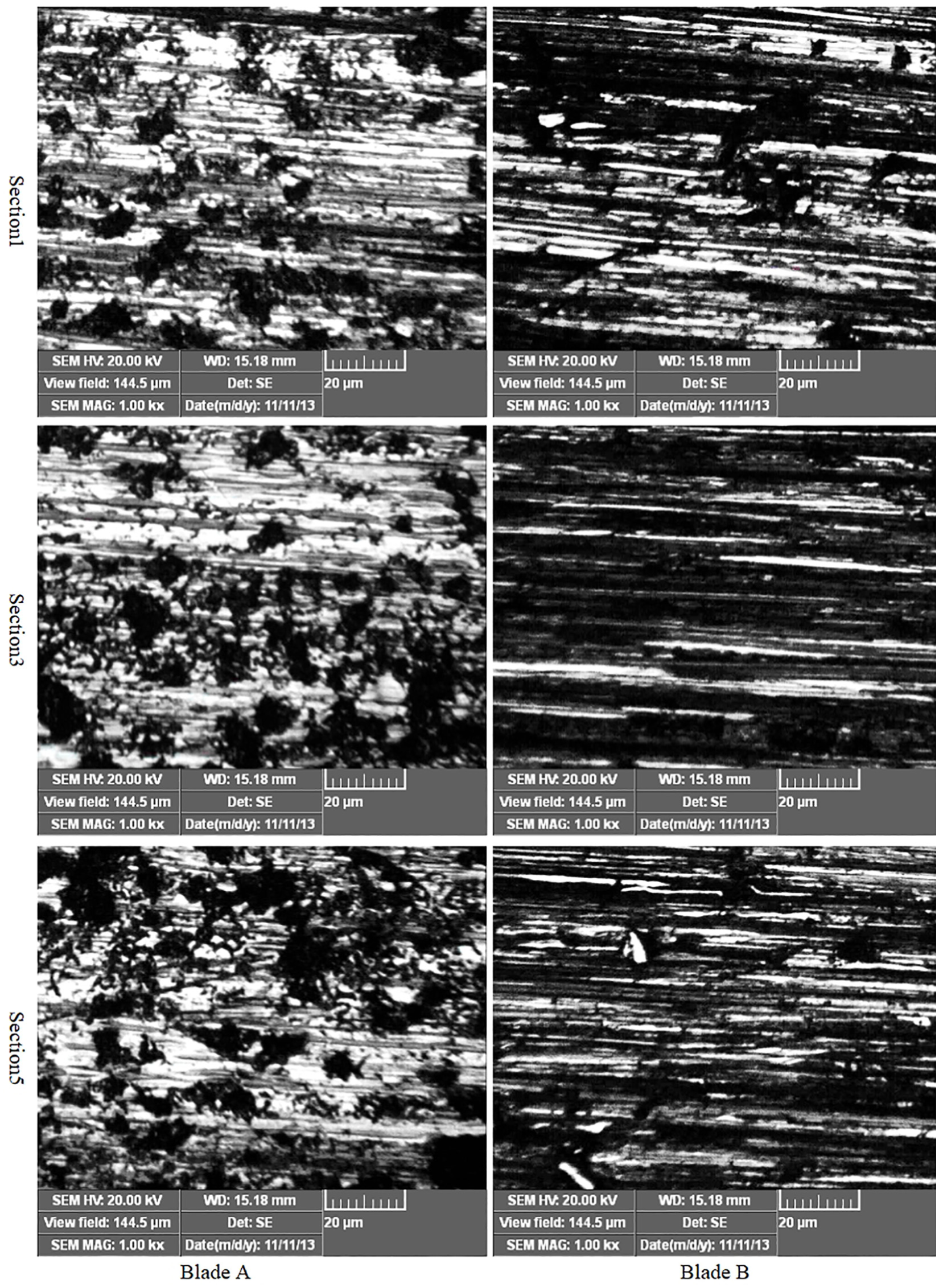
Surface topography of blisk after optimisation.
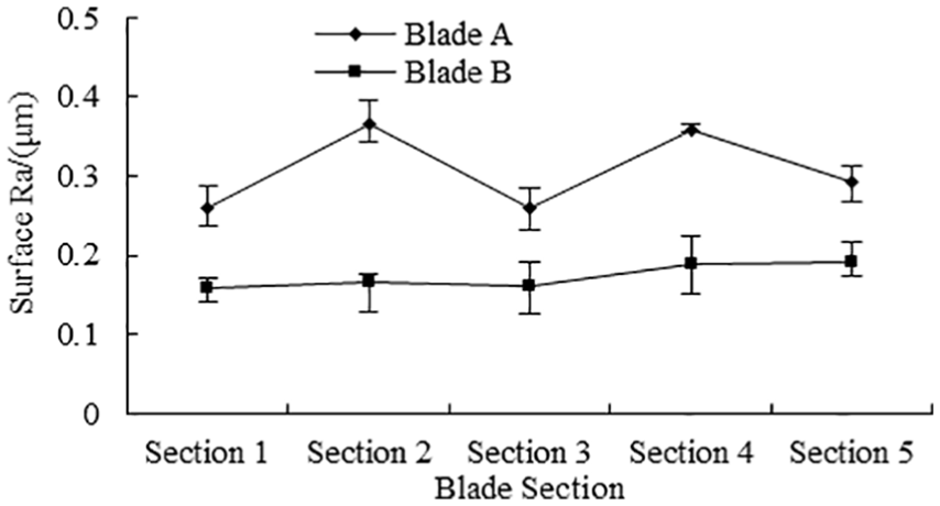
Surface roughness of blisk after optimisation.
Conclusion
This study demonstrated that the limit of the stability of the overall belt grinding of a blade is affected by the process parameters such as belt line speed, grinding feed rate, grinding pressure, hardness of the contact wheel, and contact width. The low-rigidity characteristics of blisk belt grinding system is built, which has the characteristics of tripartite low rigidity, including contact roll, bracket arm, and thin-walled blade. And the tripartite low rigidity of abrasive belt grinding is analysed, and the maximum deformation of the path node at the tip is 0.11629 mm, and at the same time, the maximum stress of the blade occurs when grinding the tip which is 10.0623 MPa. After the analysis of influencing factors, the stability of the grinding process and its indicators are obtained: the sand linear velocity is 3 m/s and its indicator is 5.823, the grinding positive pressure is 4 N and its indicator is 4.52, the feed speed is 0.6 m/min and its indicator is 5.787, and the hardness of the contact wheel is 55 Hs/A and its indicator is 7.233. After optimisation, the cross-sectional profile is 0.031–0.041 mm and the surface roughness is 0.1–0.2 μm; the surface is smoother and has better consistency. The deformation and stress on the blade would be simulated, but it is difficult to testing online; this would be limited to analysis mechanism of the vibration during blisk belt grinding, so the future research would be concentrated on this problem.
Footnotes
Appendix 1
Declaration of conflicting interests
The author(s) declared no potential conflicts of interest with respect to the research, authorship, and/or publication of this article.
Funding
The author(s) disclosed receipt of the following financial support for the research, authorship, and/or publication of this article: This work was supported by the National Natural Science Foundation of China (Grant No. 51705047), Technological Innovation and Application Demonstration of Chongqing (cstc2018jszx-cyzdX0061), and Fundamental Research Funds for the Central Universities (2018CDQYCD0038).