
Abstract
Variable pitch and helix end mills disturb the regeneration mechanism that causes chatter vibrations, and as such, they enable stable, high-performance, and high material removal rate milling processes. The regeneration mechanism is altered by the non-uniform tool geometry that results in multiple or distributed delays between vibrations imprinted on the machined surface. The design procedure for these cutters needs characterization of the stability diagrams to decide the non-uniform geometry that improves the absolute minimum stable depth of cut as well as the changes in the size and location of stability pockets. This paper presents a unified method to rapidly analyze the stability of variable helix and pitch cutters with multiple or distributed delays using a non-iterative multi-frequency domain approach that uses the Nyquist criterion to check stability at every spindle speed and depth of cut tuple. Predictions are benchmarked with the established and widely used semi-discretization method and verified with previously published experimental data, which are further validated by our own experiments. The proposed method is as accurate as of the established one while offering computational savings of up to 94%. Since explorations of alternate and better designs were potentially precluded by the computational inefficiency of previous methods, and since the method proposed herein is fast and accurate, it can help to accelerate the design of improved variable helix and pitch end mills for their use in industrial settings.
Introduction
Chatter vibrations may cause unrepairable damage on the machined surface, premature tool failure, and damage to the critical machine tool components. Chatter must hence be avoided. Chatter is a function of the machine flexibilities, the tool’s geometry, the workpiece material being cut, and the cutting parameters. Hence, to avoid it, machines can be stiffened through active/passive damping, by changing the tool geometry, or by selecting appropriate cutting parameters. Integration of dampers is not always feasible. Moreover, since certain applications may demand the use of specific workpiece materials, changing them may also not be possible. Hence, the use of tools with non-uniform geometries is sometimes preferred as a method to avoid chatter. Their working principle relies on disturbing the regeneration mechanism responsible for chatter. Of the different possible non-uniform tool geometries, this paper is concerned only with non-uniform tool geometries of the variable pitch type,1–5 of the variable helix type,6–8 and of the variable pitch and helix type.9–16
Cutters with non-uniform geometry can be designed based on the stability diagrams that show the effects of tool geometry on the limiting depth of cut and the size and location of stability pockets. Prediction of these stability diagrams requires solving delay differential equations that describe the regeneration effects. The equations can be solved using time and frequency domain solution methods.
In the time domain, methods include those that use the standard forward Euler numerical integration scheme, 17 the semi-discretization method (SDM),9,11,16 the full-discretization method, 13 the temporal finite element analysis, 9 the subspace iteration technique, 4 the cluster treatment of characteristic roots, 2 the enhanced multistage homotopy perturbation method, 10 the integral interpolation method, 5 and the generalized Runge-Kutta method. 14
In the frequency domain, stability diagrams can be obtained via the zero-order approximation (ZOA) method for the case with single, constant delay18,19 or by using an iterative multi-frequency solution (MFS) approach that accounts for the multiple or distributed delays.8,12 The ZOA method, which considers time-averaged direction coefficients, has also been utilized to analyze stability for the variable helix/pitch cutters1,7,12 by averaging the multiple delays. Applying the shift theorem in the Laplace domain, an unstable island for a variable helix tool6 has also been analyzed by averaging the delay and calculating the magnitude of the overall governing transfer function corresponding to the critical frequency obtained from the Bode diagram. Although methods that average the delay may be inaccurate, they are fast. This is in contrast to the iterative multi-frequency solutions and/or the time-domain methods, which are accurate, but computationally slow.
Since cutters with variable pitch and helix are used primarily for their chatter-free high material removal rate capabilities, they are designed to eliminate chatter. As such models should be able to predict their stability behavior accurately and rapidly such as to facilitate exploring different cutter designs and cutter geometry optimization. In response to the need for a fast, non-iterative, and accurate method to solve for the stability of cutters with non-uniform geometries which can be used to explore alternate and improved design options by the industry, this paper presents a non-iterative multi-frequency solution (MFS) approach to analyze the stability of variable helix and pitch cutters with multiple or distributed delays.
Multi-frequency solution (MFS) methods were originally proposed 20 to account for the higher harmonics of the dynamic cutting force characteristics that were averaged in its precursor method, the zero-order approximation (ZOA) method. 18 The method was further developed 21 for systems with multiple delays using a multi-dimensional bisection method used to find the iterative roots of the resulting transcendental characteristic equation. Furthermore, to truncate the infinite-dimensional matrices, the method was numerically implemented to calculate the stability by finding the winding number of the closed contour around the origin. 12 The method was further extended 8 to solve the stability of the multi-input-multi-output (MIMO) system by exploiting the periodicity and high-frequency behavior of the harmonic doubly-infinite transfer function. However, these methods are iterative and computationally costly.
To address the issue of the requirement of a solution method that is fast and accurate, this paper proposes to characterize stability using the multi-frequency solution method in conjunction with the Nyquist criterion to check for stability of systems with multiple delays. The proposed algorithm avoids iterations as it is solely based on the Nyquist criterion that checks whether the given conditions lead to a stable system. This makes predictions computationally efficient. In our prior work, the Nyquist criterion was used to check for stability of serrated cutters with distributed delays, 22 and it was shown that the Nyquist check can easily be extended from its prior use in stability analysis of systems with constant delays23,24 to analyze the stability of systems with multiple delays. Serrated cutters have very different cutting mechanics and delay characteristics than the variable pitch and helix cutters of interest in this paper. As such, though our prior work and the present work both use the MFS approach to solve for the stability, formulations for both are fundamentally different. Since there is no prior reported work that discussed solving for the stability of milling with variable pitch variable helix tools using a non-iterative MFS approach, our methods contribute to the state-of-the-art.
The remainder of the paper is organized as follows. At first, the cutting force model and the governing equations of motion for tools with non-uniform geometries are briefly described. In the subsequent section, the multi-frequency solution (MFS) is presented to characterize the stability of variable pitch/helix tools using the Nyquist stability criterion. The generalized nature of our proposed solution is demonstrated by discussing separate cases for tools with variable helix and pitch, for tools with variable pitch, and for tools with variable helix. In the section after, the stability solution using the established semi-discretization method (SDM)25,26 is briefly discussed. Among the time-domain methods, SDM is the most popular one due to its convergence and accuracy. We hence choose the SDM as a benchmark for our simulations, rather than other time-domain methods such as the temporal finite element analysis. 9 Since the SDM handles multiple delays by discretizing them without the need of averaging and/or approximating delays, the method is accurate and computationally more efficient than other time/frequency domain schemes, and hence it has been preferred by others to characterize the stability of non-uniform cutters.9,11 In the last section, our results are benchmarked with published experimental findings1,7,11 and with those obtained using the SDM. Having benchmarked with existing works, the proposed stability model is further validated with our own experiments, which are followed by the main conclusions.
Cutting mechanics and dynamics
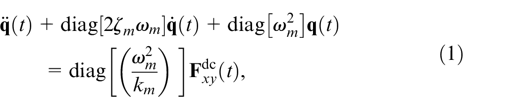
The dynamic cutting force model and the governing equations of motion that are to be solved to characterize the stability of end mills with variable pitch/helix are outlined here. The regenerative chatter stability model presented herein is based on Altintas et al. 1 and Sims et al. 9
The schematic of a two-degree-of-freedom milling process is shown in Figure 1. A cutter with a diameter
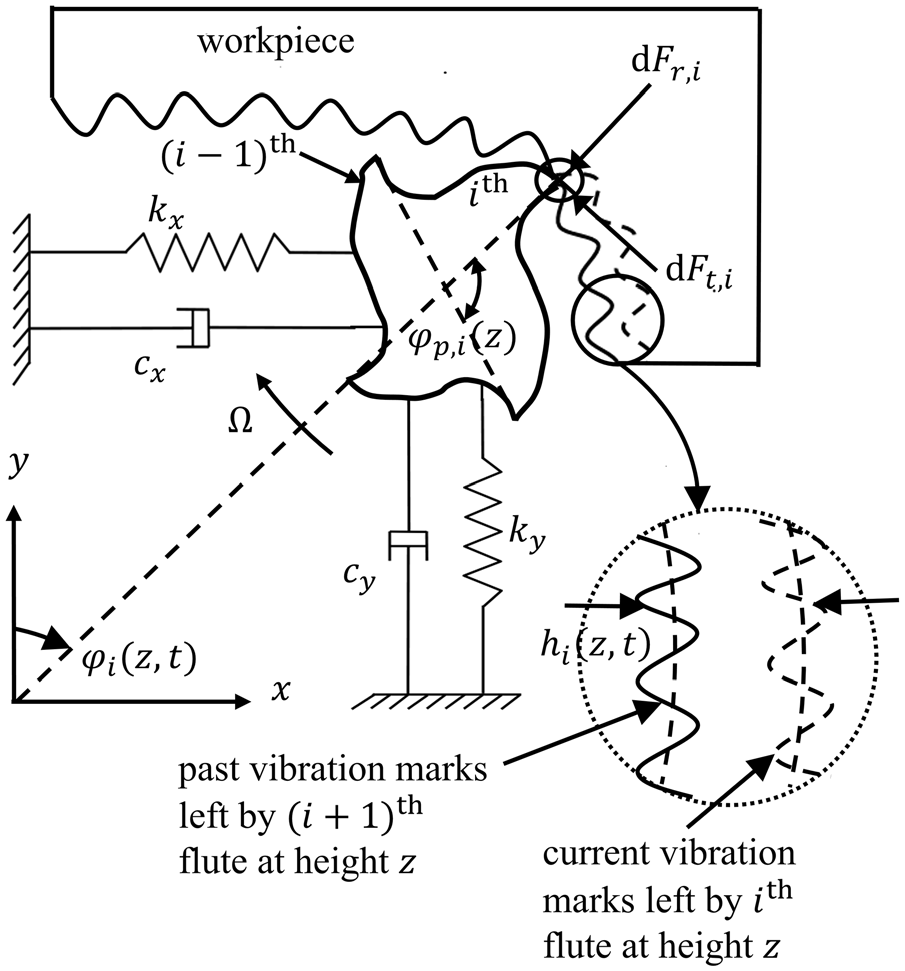
Cross-sectional schematic of a flexible end mill with vibration marks left on the workpiece that are machined by consecutive flutes.
where,
where,
and,
where,
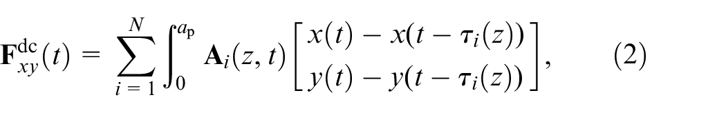
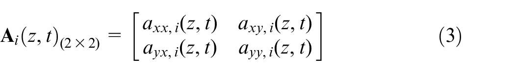
For a variable pitch/helix cutter, the pitch angle varies from one flute to another as well as along the axial position. Hence the corresponding time delay
where,
To solve the stability of variable pitch/helix cutters, the next section discusses the multi-frequency method. 20
Stability prediction using multi-frequency solution (MFS)
This section details methods to solve for the stability of end mills using the frequency domain multi-frequency solution (MFS) method 20 by applying the Nyquist criterion. At first, the generalized stability for the tools with variable pitch and helix is presented, which is followed by presenting solutions for the tools with only variable pitch and subsequently for the tools with only variable helix.
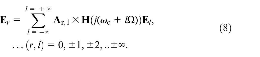
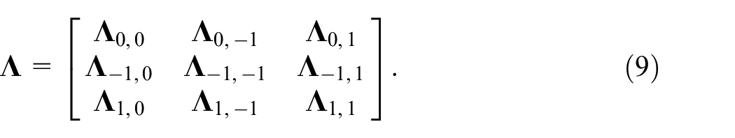
In the MFS method,
20
the time-varying coefficients (
where,
where,
where,

where,
As
For cutters with only the helix being variable,6–8 the time delay varies with height and flute. Hence the stability of variable helix cutters can be solved using equation (8) and following a similar procedure as described above. On the other hand, for cutters with only the pitch being variable,1–5 the time delay varies only with the flute and not with flute height. Hence the dependence on the time delay
The clear advantage of MFS over SDM methods is that the natural frequencies would not influence the simulation performance or the minimum simulated spindle speed. Moreover, various effects such as process damping can be added in a very systematic manner without complicating the simulations. MFS method is normally applied with the iterations in which the eigenvalues are searched until certain conditions are met. With our use of the Nyquist criterion, we show that the iterations can be avoided, and a significant computational saving can be achieved.
To contextualize the efficacy of our proposed method, our predictions are benchmarked with the established semi-discretization method, 25 which is briefly outlined next.
Stability prediction using the semi-discretization method (SDM)
By decomposing the governing delay differential equation (1) to its first order discretized form and following the semi-discretization method for the case of stability with multiple delays,
25
the transition matrix
Benchmarking with state-of-art numerical simulation and experiments
The results obtained using our proposed multi-frequency solution (MFS) method are benchmarked with published experimental results and with our own experiments. The well-established high-fidelity semi-discretization method (SDM) 25 is also used for the verification of stability boundaries. The verification and validation of the proposed stability models are shown in Figures 2 to 4 for three four-fluted cutters of interest: one with variable pitch and helix, 11 another with variable pitch, 1 and one with variable helix. 7 Additionally, another case for a three-fluted cutter with variable pitch is verified in Figure 5 to demonstrate that the proposed method can also capture Hopf- and flip-bifurcations. 9 A comparison between cases is not intended or warranted. Each figure discusses a separate case from the literature.
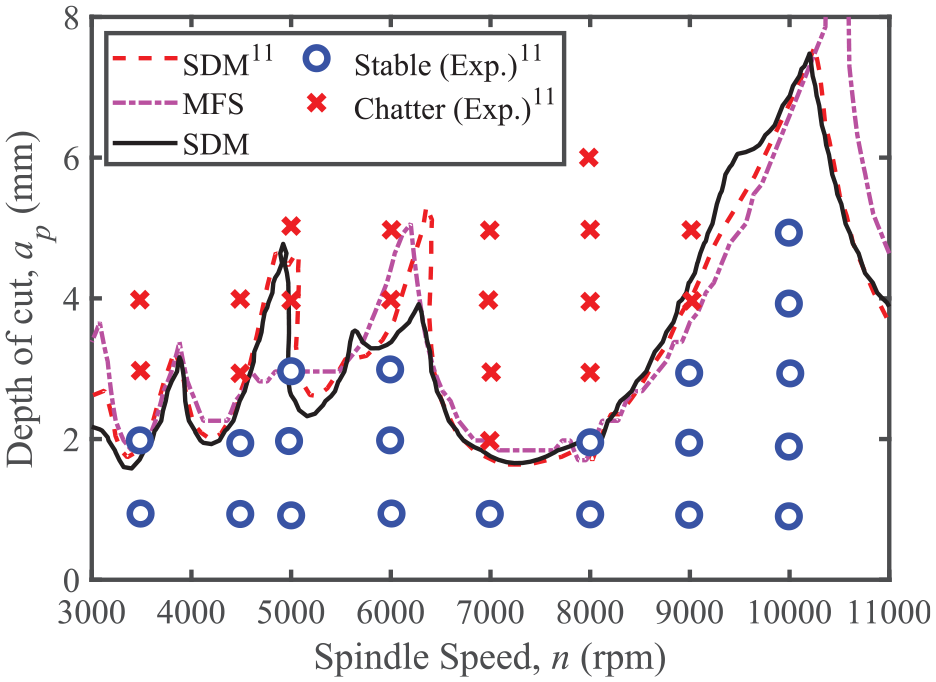
Comparison of experimental results (from Jin et al. 11 ) and the predicted chatter stability diagrams using MFS and SDM for a four-fluted end mill with variable pitch and helix.
Comparison of experimental results (from Altintas et al. 1 ) and the predicted chatter stability diagrams using MFS and SDM for a four-fluted end mill with variable pitch angle.
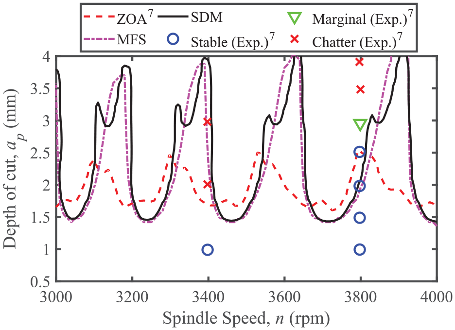
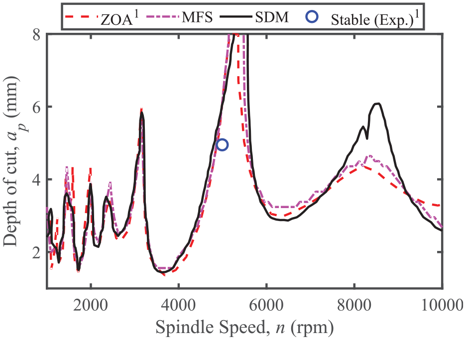
Comparison of experimental results (from Comak and Budak 7 ) and the predicted chatter stability diagrams using MFS and SDM for a four-fluted end mill with variable helix.
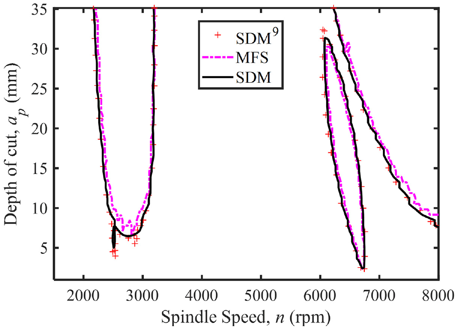
Verification of stability lobes for three-fluted variable pitch end mill. See Figure 10(a) by Sims et al. 9 for the original stability lobes diagram predicted using SDM.
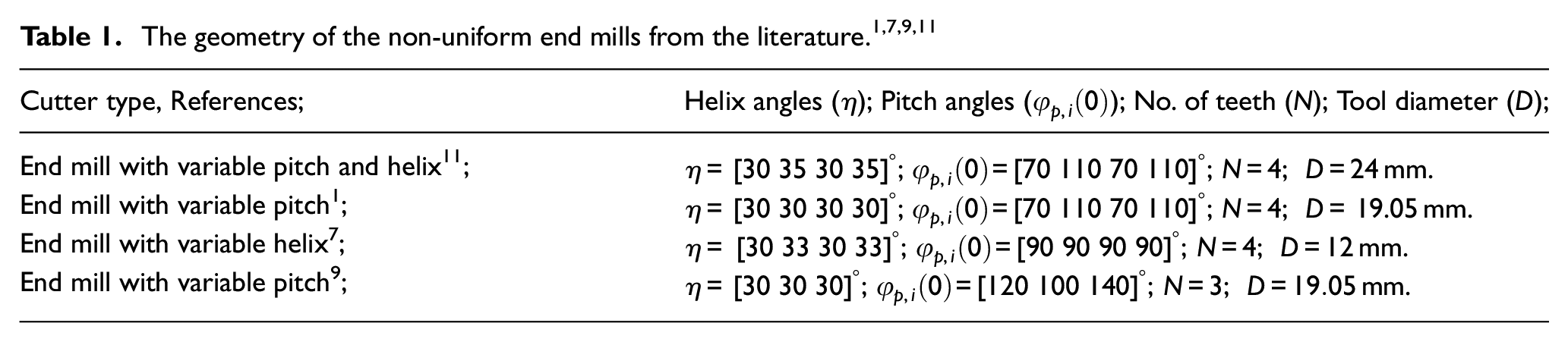
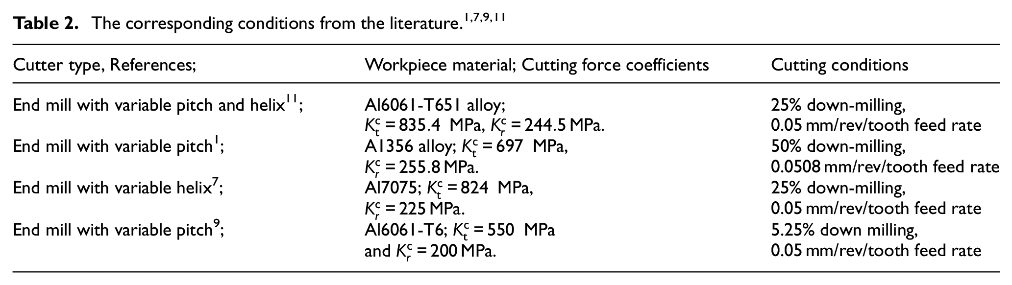
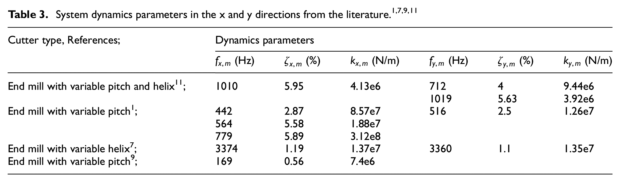
The geometry of cutters under consideration1,7,9,11 in this study are summarized in Table 1. The workpiece material, cutting force coefficients, and corresponding cutting conditions are summarized in Table 2. The system dynamic parameters in the x and y directions are listed in Table 3.
In the MFS method, four harmonics (
In Figure 2 the experimental validation of chatter stability is shown for a four-fluted end mill with variable helix and pitch using the experimental data from Jin et al. 11 The tool parameters and cutting scenario as considered in Jin et al. 11 are described in Tables 1 to 3. The stability diagram is predicted using the Nyquist check for the MFS method, which is compared with the SDM result using the same parameters as their experimental work. 11
Although the overall prediction accuracy of the limiting depth of cut by MFS is acceptable in Figure 2, and though predictions agree with experimental observations, small differences with SDM are noticeable at speeds near 5000, 6000, and 10,000 rpm. Differences could be attributed to a potentially insufficient number of harmonics of the spindle rotation frequency being considered as part of the eigenvalue solution, 29 and/or to simulation artifacts due to the multiple possible solutions, and/or to the inclusion of false solutions that do not correspond to the chatter frequency. 30 Since the periodicity of the dynamic cutting force for the four-fluted cutter with alternating pitch and helix angles under consideration herein is half the tooth passing frequency (or twice the spindle rotation frequency), two of the four harmonics of the spindle rotation frequency would have no effect. As such, since the odd harmonics would play no role in the solution, the MFS method could be reformulated to potentially include higher harmonics that influence the predictions. Those investigations could form part of future studies.
Since the proposed MFS method is generalized, our stability model is further validated for a four-fluted end mill with variable pitch angles using the experimental data from Altintas et al. 1 which is shown in Figure 3. In Altintas et al. 1 the milling tool was investigated under the conditions listed in Tables 1 to 3. Predictions were benchmarked against the established semi-discretization method (SDM).
As is evident from Figure 3, the prediction accuracy of MFS may be deemed acceptable, even though it may need improvement around 8000 rpm, where it differs from the SDM predicted boundary. In this case, only one experimental data point was reported in Altintas et al. 1 and our predictions can correctly classify that data point. Interestingly, the MFS predicted boundary is not very different than that obtained from the ZOA method. The ZOA method gives a single solution at the chatter frequency, whereas, MFS scans the neighboring harmonics. Since the Nyquist stability criterion does not know whether the eigenvalue is physically sensible, the solution may converge to ZOA as observed in Figure 3. Getting the MFS prediction to better agree with the SDM at all spindle speeds can be addressed in a future study by optimizing the simulation parameters.
To further verify and validate the proposed models, the last case of experimental validation of chatter stability is presented for a four-fluted end mill with a variable helix using the experimental data from Comak and Budak. 7 The cutting conditions and tool geometries as considered in Comak and Budak 7 are provided in Tables 1 to 3. Experimental observations are overlaid over model predictions in Figure 4. As is evident, model predictions using MFS and SDM, in general, agree with each other, and with experimental observations. The small prediction errors that show similar patterns in every stability pocket could indicate a simulation artifact that needs further investigation due to the natural frequency of the tool being very high when compared to the spindle rotation frequency.
To furthermore verify the efficacy of our proposed stability model to capture the so-called “islands of instability” arising due to period-doubling bifurcations, one additional case is illustrated in Figure 5 for a three-fluted variable pitch cutter. 9 The cutting simulation data and tool geometries as considered in Sims et al. 9 are given in Tables 1 to 3. It can be seen that the stability island is captured correctly by our proposed MFS.
Having benchmarked the results obtained using our proposed multi-frequency solution (MFS) method with published experimental results, we further validate our proposed stability model with our own experiments. We present here the experimental validation of predicted stability behavior for a four-fluted end mill with 16 mm diameter, and with variable pitch and helix (
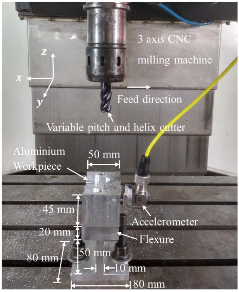
Experimental setup for chatter test of a variable pitch and helix cutter using Aluminum workpiece mounted over web-shaped flexure.
As shown in Figure 7, the stability lobes using predicted by the proposed MFS method are compared with SDM and experimental results. In the MFS method, four harmonics (
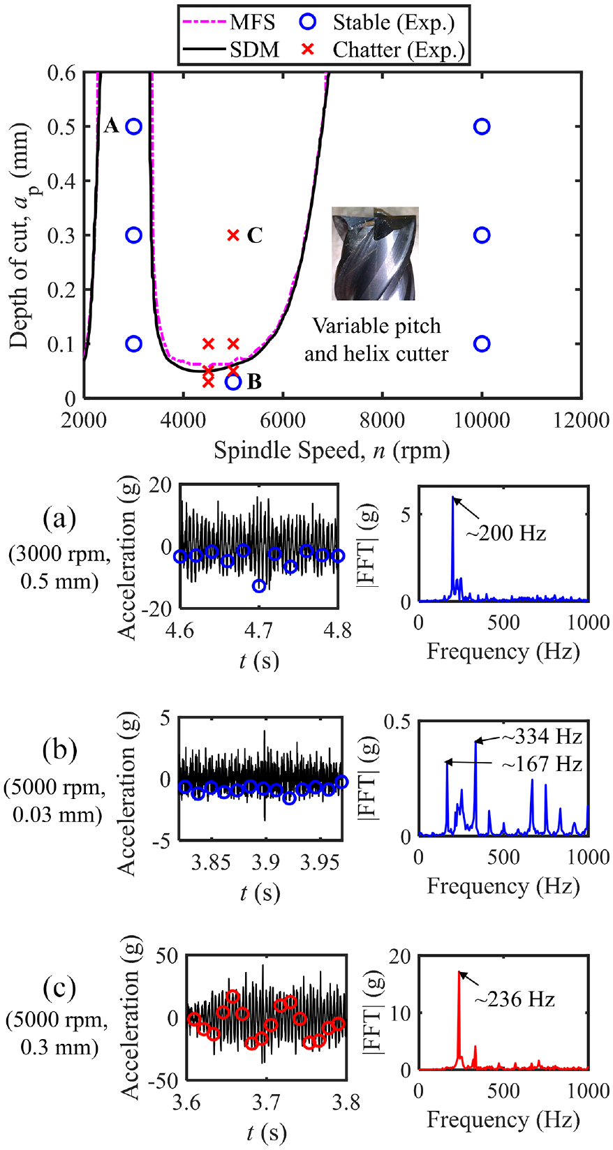
Stability behavior for a four-fluted variable pitch and helix cutter for slot cutting with 0.15 mm/tooth/rev feed rate.
As seen in Figure 7, the proposed MFS method compares very well with SDM results and also gives very good agreement with experimental results. To validate the predicted stability, slot milling experiments were conducted with a feed rate of 0.15 mm/tooth/rev. A uniaxial accelerometer was used to measure the response of the flexure during cutting. The cut was categorized as stable when the FFT of the response signal was dominated by the spindle frequency or tooth passing frequency and/or its harmonics. The chatter condition was detected when the FFT of the response signal was dominated by a peak close to the natural frequency of the system and one that is not a harmonic of the spindle frequency and/or the tooth passing frequency. Additionally, the chatter case was also confirmed by sampling the signals at once-per-spindle-revolution. If the milling response was synchronous with the spindle rotation, the cut was identified as stable, and if not, it was labeled as an unstable cut. 22
The validation experiments were conducted at four different spindle speeds, as shown in Figure 7. Representative measured responses and their frequency spectra (FFT) are shown at points A (depth of cut of 0.5 mm, spindle speed of 3000 rpm), B (depth of cut of 0.03 mm, spindle speed of 5000 rpm), and C (depth of cut of 0.3 mm, spindle speed of 5000 rpm). For milling at stable zones, that is, below the predicted boundary (at points A and B), the FFT is dominated by a peak at ∼200 and ∼334 Hz respectively which are the corresponding tooth passing frequencies. For cutting at unstable zones that lie above the predicted boundary (at point C), the FFT is dominated by a peak at ∼236 Hz which is above the natural frequency of the flexure. Moreover, the once-per-revolution sampled data at point C shows a non-synchronous response and quasiperiodic Hopf instability, 17 which confirms the chatter condition. On the other hand, the once-per-revolution sampled data for cutting at points A and B approximates a straight line behavior suggesting that the cut is stable, which is also confirmed by the frequency spectra. Hence, the predicted stability is deemed valid.
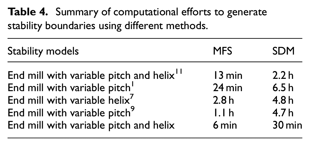
From Figures 2 to 5 and 7, it is observed that the proposed MFS method is almost as accurate as the state-of-art semi-discretization method to capture the stability lobes. The accuracy, evaluated based on the absolute lowest stable depth of cut, of the proposed MFS method varies between ∼1%−12% when compared to SDM. Simulation grid refinement can further improve prediction accuracies, albeit at the cost of computation. Minor discrepancies can be resolved in future simulation parameter optimization studies. From the point of computational efficiency, the proposed MFS method outperforms SDM. For the cutter with variable pitch and helix, 11 the MFS method takes ∼13 min to generate stability boundaries in contrast to the SDM method which takes ∼2.2 h, reducing simulation times by up to ∼90%. Similarly, for the variable pitch cutter, 1 the variable helix cutter, 7 the other variable pitch cutter, 9 and our variable pitch and helix cutter ∼94%, ∼42%, ∼77%, and 80% of computational improvements are achieved respectively using the proposed MFS method. A summary of the computational efforts to generate stability boundaries is presented for all five cutters in Table 4. All computer programs (Supplemental Material) were executed in MATLAB® 2018a and implemented on a computer with specifications of: Intel Core (TM) i7 Processor, 3.6 GHz, 16 GB RAM.
Summary of computational efforts to generate stability boundaries using different methods.
Conclusions
This paper presented a fast and accurate method to evaluate the stability behavior of variable helix and pitch end mills. The method uses the multi-frequency solution (MFS) approach in conjunction with the Nyquist criterion to check for the stability of systems with multiple delays. This is the first time that the MFS method was formulated and used in a general and non-iterative manner to solve for the stability of variable helix and pitch tools. Predictions with the proposed method were found to agree with data from already published experimental findings for three four-fluted cutters and one three-fluted cutter having different combinations of variable pitch and/or helix geometries. The proposed model was further validated with our own experimental results. Predictions were also benchmarked with stability evaluated using the established semi-discretization method (SDM). Computational improvements of up to 94% were achieved.
Multi-frequency solution methods of simulating stability are as accurate as time-domain methods but the former has not received as much research attention as time-domain methods have to improve their computational efficiency. Furthermore, frequency-domain methods can also address some of the shortcomings associated with time-domain methods that make time-domain simulations computationally inefficient. Such as those that require simulation of vibrations that involve a wide range of natural frequencies, or that require simulating in very small spindle speed steps such as is required in the process damping zone. As such, our contribution of making the multi-frequency domain method non-iterative and fast can open up new possibilities for simulating more complex machining stability cases than the variable pitch and helix cases discussed herein.
Though we have addressed one aspect of making the MFS method fast, further research is still necessary to resolve issues with the MFS method for when vibration modes are closely spaced, or for when there could be multiple vibration modes in multiple directions. Further research could also explore making the MFS method more efficient with the use of adaptive frequency stepping as necessary. Moreover, since the proposed MFS method is frequency-based, interactions of spindle/cutting harmonics with one of the many modes of a multi-mode system are inevitable. These interactions may result in differences in stability lobe diagrams evaluated by the proposed method and by those evaluated with the gold-standard semi-discretization method. Besides, the effects of including more harmonics of the spindle rotation frequency, and ways to avoid false solutions and simulation artifacts need further investigation in future studies. However, despite the potential interactions and minor differences, the global results and trends of the stability diagrams predicted by the proposed method were found to agree very well with the semi-discretization method (SDM), and with the experimental data.
Since explorations of alternate and better designs were potentially precluded by the computational inefficiency of previous methods, and since the method proposed herein is fast and accurate, it can help to accelerate the design of improved variable helix and pitch end mills in industrial settings.
Supplemental Material
sj-7z-1-pib-10.1177_09544054221126967 – Supplemental material for Rapid stability analysis of variable pitch and helix end mills using a non-iterative multi-frequency solution
Supplemental material, sj-7z-1-pib-10.1177_09544054221126967 for Rapid stability analysis of variable pitch and helix end mills using a non-iterative multi-frequency solution by Pritam Bari, Zekai Murat Kilic and Mohit Law in Proceedings of the Institution of Mechanical Engineers, Part B: Journal of Engineering Manufacture
Footnotes
Declaration of conflicting interests
The author(s) declared no potential conflicts of interest with respect to the research, authorship, and/or publication of this article.
Funding
The author(s) received no financial support for the research, authorship, and/or publication of this article.
Supplemental Material
Supplemental material for this article is available online.
References
Supplementary Material
Please find the following supplemental material available below.
For Open Access articles published under a Creative Commons License, all supplemental material carries the same license as the article it is associated with.
For non-Open Access articles published, all supplemental material carries a non-exclusive license, and permission requests for re-use of supplemental material or any part of supplemental material shall be sent directly to the copyright owner as specified in the copyright notice associated with the article.