
Abstract
It is crucial to properly design the fixturing layout described by fixturing parameters, such as the fixturing sequence, the placement of clamping force, the locator position, and so on. This is because the clamping deformation of the thin-walled workpiece can influence extremely the machining accuracy and surface quality. Generally speaking, the finite element method can be used to easily obtain the deformation rule of the workpiece caused by one single fixturing parameter. But it is difficult to reveal the relationship between the multiple fixturing parameters and the clamping deformation of workpiece. Therefore, the workable finite element model of multi-fixturing layout is above all established for the thin-walled workpiece. Thus, clamping deformations can be calculated to be the training samples of the neural network. Next, according to the training samples, the prediction model is suggested for obtaining the clamping deformation from multiple fixturing parameters. When the prediction errors are defined as fitness function, the genetic algorithm is developed to search the optimal initial weights and thresholds for the neural network. The optimized neural network has better generalization and prediction ability than the non-optimized one. Ultimately, the embedded optimal model with the objective of minimizing the clamping deformation is presented for a multi-fixturing layout. When the individual fitness of each generation is constructed as a function of the clamping deformations, the genetic algorithm can be skillfully used to solve the embedded optimal model. Moreover, the experiment is conducted to validate the prediction method with good agreement between the predicted results and the experimental data. The above presented “analysis—prediction—control” method of clamping deformation not only improves the calculation efficiency of clamping deformation but also provides a basic theory of fixturing layout design for the thin-walled workpiece.
Keywords
Introduction
With the rapid development of the aeronautical and astronautical industries, high-performance aircrafts are increasingly required. The thin-walled workpieces have been widely employed in aircrafts due to their light weight and other advantages. However, in the machining process, which includes fixturing and cutting, the workpiece is always accompanied by a different degree of deformation. In the cutting process, besides some important factors such as the cutting forces,1–4 the material removal, 5 and so on, the clamping forces in the fixturing process are also a crucial consideration to affect the workpiece deformations. 6
Kashyap and Devries 7 employed the finite element method to analyze the normal clamping deformation of a thin plate-shaped workpiece at the locating points. By changing the positions of three locators on the workpiece bottom, the finite set of clamping deformations are able to be obtained. Consequently, the best layout of locators can be determined by seeking minimum clamping deformation. Qin et al. 8 used the finite element method to simulate the clamping deformations of a thin frame-shaped workpiece. The clamping deformations of long frame wall in contact with the clamps were selected to reveal the influence of multiple clamps and their application sequences on the workpiece deformations. Siebenaler and Melkote 9 were interested in the relationship among the friction coefficient between the workpiece and the fixels (including locators and clamps), the mesh size, and the clamping deformations. The validation of simulated results had been carried out in comparison with the experimental values. After the clamping deformation obtained by the finite element method, Cai et al. 10 adopted the nonlinear programming method to find n of the “n-2-1” locating layout in order for the clamping deformation of a thin plate-shaped workpiece to achieve the minimum value. Kaya 11 and Chen et al. 6 have established the optimal model with the objective of minimizing the workpiece deformation. The genetic algorithm was utilized to find the optimal locator positions for the optimal model. In addition to the location of the locators and clamps, Liao 12 was concerned with the number of these fixels. So the genetic algorithm was also developed to solve this problem for minimizing the workpiece deformation. Padmanaban and colleagues13,14 considered the effect of periodic forces (i.e. clamping and machining forces) on the dynamic response of workpiece. The evolutionary algorithms were employed to achieve the optimal fixturing layout with the minimum workpiece deformation. The emphasis of the literature 13 was on the comparison of genetic algorithm with ant colony algorithm, whereas the literature 14 discussed the advantage of the ant colony algorithm–based continuous optimization method over the ant colony algorithm–based discrete optimization method. Liu et al. 15 used the finite element method to calculate the clamping deformation of a thin plate-shaped workpiece. In his study, one more locator would be increased at the corresponding placement when the maximum clamping deformation occurred on the second locating reference. Another locator was continued doing so until the clamping deformation decreased to be within the machining accuracy. After the number of locators was determined, the heuristic rules were proposed to obtain the optimal locator positions. Only in doing so can the maximum clamping deformation from all mesh nodes be minimized. In the above-mentioned research works, the finite element method is applied for the clamping deformation of the workpiece; however, it performs with low-efficiency as it requires heavy computations.
The back propagation (BP) neutral network can approach any nonlinear function with arbitrary accuracy. It has been widely applied in the fields of the pattern recognition, function approximation, automatic control, signal processing, and so forth. Vishnupriyan et al. 16 measured the acceleration signals of workpiece processing references to obtain the workpiece dynamic motion. If these experimental results were used as training samples, the workpiece dynamic motion can be predicted from the position of fixels. According to the orthogonal experimental design method, Xin et al. 17 carried out the milling experiment for the milling deformations of the workpiece under different milling parameters. A milling deformation prediction model was developed by taking the experimental data as the training samples of BP neural network. In order to create the nonlinear mapping model of BP neural network, Li 18 considered the spindle speed and the feed per tooth as the input neurons in calculating the workpiece deformation. The genetic algorithm was subsequently applied to optimize the milling parameters for the aim of minimizing deformation with the lowest cost and highest efficiency. However, these investigations focused primarily on the influence of cutting parameters on the workpiece deformation. To detect the influence of other parameters on the workpiece deformation and predict the deformation, Selvakumar et al. 19 employed the neural networks to construct a prediction method of workpiece deformation. The signal to noise ratio (SNR) ratios of the predicted workpiece deformations can quickly be calculated for the fixel positions. The best fixel positions can be selected according to the minimum principle of the SN ratio. Furthermore, Selvakumar et al. 20 adopted the genetic algorithm to find the optimal fixel positions, which can minimize the workpiece deformation. But in their surveys, the neural networks and genetic algorithm were analyzed only with consideration of the influence of their parameters. Note that the randomicity of initial weights and thresholds can cause the different predicted results with same input samples. Moreover, the multiple clamps were assumed to exert on the workpiece simultaneously.
In order to minimize the influence of the fixturing parameters on the workpiece deformation, the emphasis of this article is on the more effective planning of multi-fixturing layout for a thin-walled workpiece. First, the finite element model of the thin-walled workpiece during a fixturing procedure is presented to obtain the best fixturing layout. This model calculates the clamping deformations, effected by the clamping forces, fixturing sequences, and locator positions, to be the training samples. Under the conditions of given clamping forces, the nonlinear mapping from the fixturing sequences and locator positions to the clamping deformations is created by virtue of a BP neural network. Then, with its help the model can successfully forecast the deformation of thin-walled workpiece. Finally, the embedded optimal model of a fixturing layout is presented to minimize the clamping deformation. Its solution technology is also proposed to obtain the fixturing sequence and the locator position according to the genetic algorithm. Based on a limited number of simulated values of clamping deformations, the proposed method is capable of calculating the clamping deformation of the thin-walled workpiece in an arbitrary multi-fixturing layout, which greatly improves the computational efficiency. By establishing an optimal model and its solution technology for a fixturing layout, the layout can effectively reduce and control the clamping deformation of the thin-walled workpiece. It will guarantee the machining accuracy of the thin-walled workpiece.
Finite element analysis of clamping deformation
To solve the clamping deformation of the thin-walled workpiece, the friction cone constraints and the unilateral contact constraints between the workpiece and the fixture must be satisfied, as well as the static equilibrium conditions.
Static equilibrium conditions
As shown in Figure 1, a workpiece is held by m locators and n clamps. It is exerted by the external wrench
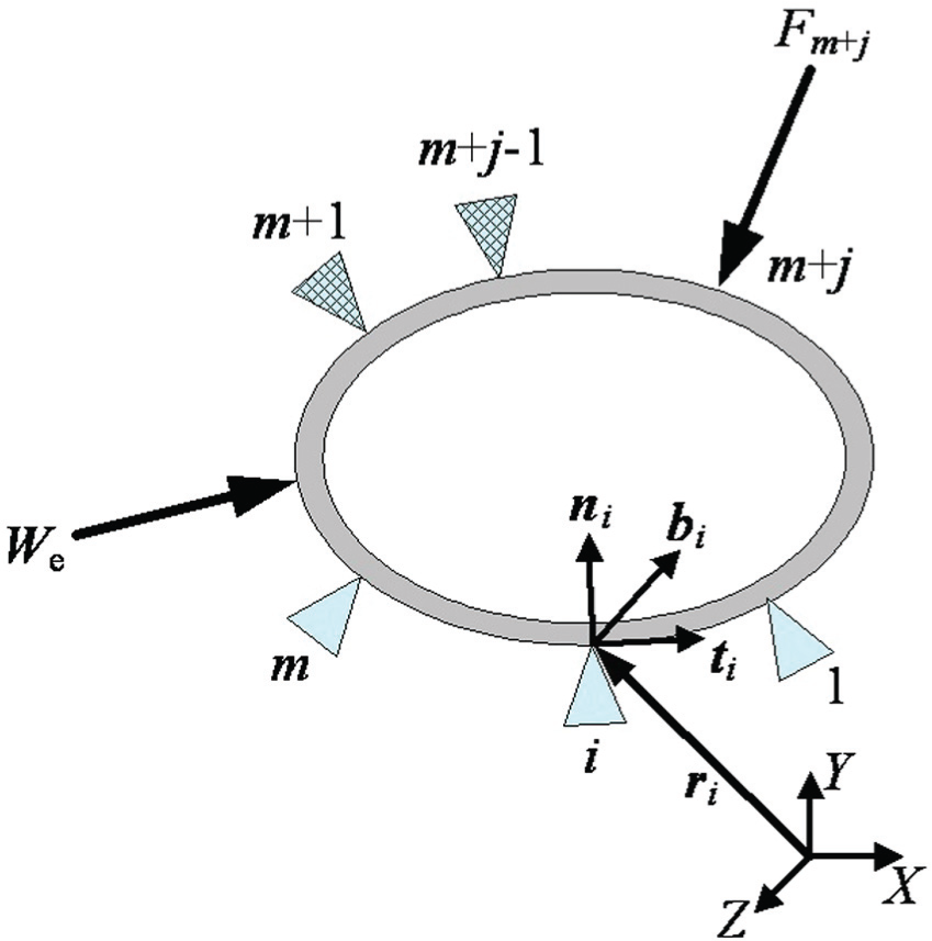
Forced status in fixturing step j.
Assume that

where
Friction cone constraints
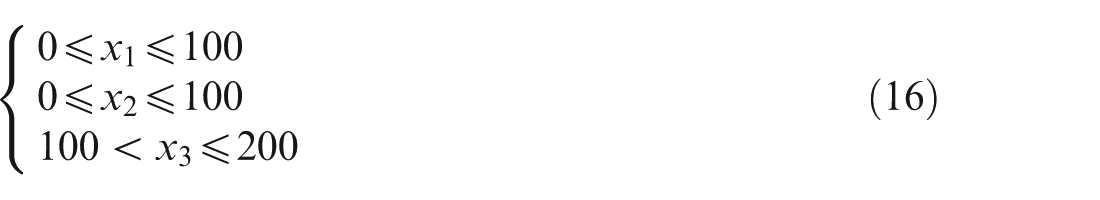
According to the Coulomb law of friction, the maximum friction force between the workpiece and fixel cannot exceed the friction cone. Consequently, the j-th fixturing step has the quadratic inequality constraints at the i-th fixel, that is

where
Unilateral contact constraints
To prevent the workpiece from detaching from the passive fixels in the fixturing process, the normal forces at any contact point between the workpiece and fixel must be compressed such as

It is known from equations (1)–(3) that the node displacement
Prediction method for clamping deformation
As stated above, if the fixturing parameters (e.g. the locator position, the fixturing sequence) are finitely given, the corresponding clamping deformations of a thin-walled workpiece can be obtained by the finite element method. However, the fixturing parameters are diverse, and it is impossible for the finite element method to calculate the clamping deformation one by one. For this reason, the prediction method of clamping deformations for the thin-walled workpiece will be discussed in this section.
Structure of neural network
BP neural network is a multilayer feed-forward network which includes the input layer, the hidden layer, and the output layer. It can approach any continuous function within arbitrary precisions. A three-layer feed-forward neural network with one hidden layer was proved to approximate any continuous function. Hence, a three-layer BP neural network is selected to predict the clamping deformation of the thin-walled workpiece for the given fixturing sequence s.
As shown in Figure 2, there are u neurons xs, i (1 ⩽ i ⩽ u) at the input layer. In the process of designing the multi-fixturing layout, the clamping deformation of the thin-walled workpiece is the key consideration to influence the machining quality. So, the clamping deformation ys, k (1 ⩽ k ⩽ w) at the k-th observation point is selected as w neurons of the output layer. Then, in connection with the learning speed and generalization ability of the BP neural network, the Kolmogorov theorem concluded the empirical formula18,21 for the neuron number v at the hidden layer, that is

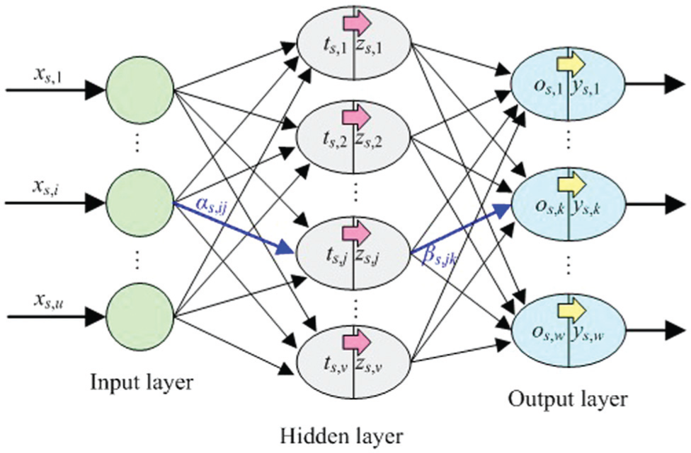
BP neural network of fixturing sequence s.
During the training process, the hyperbolic tangent function is generally selected as the transfer function of neurons in the hidden layer for the space division of different samples. The linear functions are employed as the transfer function of neurons in the output layer for the identification results of the neural network. Thus, the relationship between the input samples and the output samples 22 can be described as
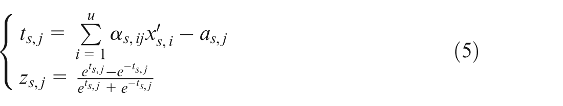
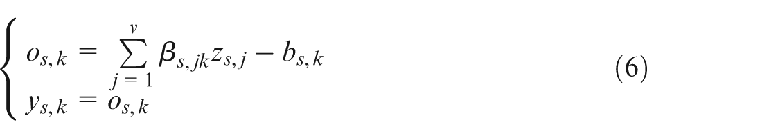
where αs,ij and βs, jk are the weights, as, j and bs, k are the thresholds, and
Selection of training samples
According to requirements of compatibility, ergodicity, and compactness of training samples, the orthogonal experimental design method is adopted to determine q groups of the fixturing parameters xs, i (including the locator position and clamping force) for fixturing sequence s. The corresponding clamping deformations are calculated as q network training samples.
In order to improve the identification accuracy of the neural network, the input samples should be normalized. Only then are the input samples with bigger values able to still fall on the position of the transfer function with a larger gradient. Equation (7) can be used for the normalization of the input samples such that each sample can be taken from the interval between 0 and 1
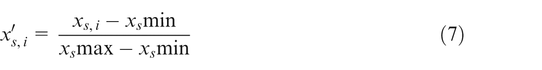
where xs, i is the input sample corresponding to the i-th fixturing parameters for the fixturing layout, and
Description of prediction model
Because the Levenberg–Marquardt algorithm has a fast convergence rate, it is chosen as the training algorithm for the feed-forward neural network to calculate the weights and the thresholds. Then, the nonlinear mapping relationship could be achieved for u inputs and w outputs in the above BP neural network. Ultimately, the MATLAB function can be used to simulate the above network, namely

where sim is the network simulation function, net
s
is the above trained BP neural network,
Determination of initial weights and thresholds
Due to the nonlinear mapping relationship between the input and the output, the weights and the thresholds can strongly influence the convergence of the training process. Obviously, it is crucial to determine the feasible values for the weights and the thresholds.
Optimal model
After the input samples are normalized, the neural network can be trained to obtain the weights αs, ij, βs, jk, and the thresholds as, j, bs, k. In connection with equations (5)–(8), these parameters in fixturing sequence s can be derived as
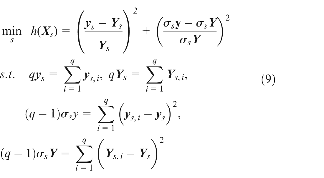
where q is the group number of input samples/output samples, which can be determined by the uniform design method.
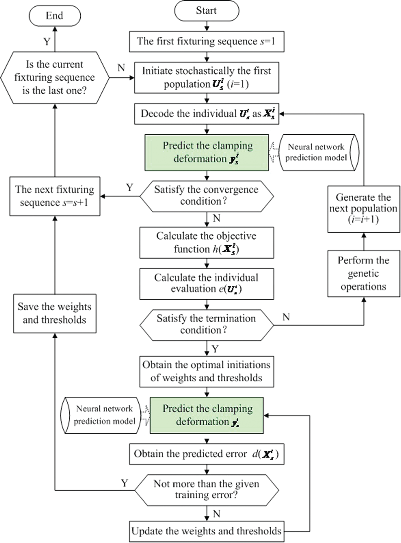
Solution technology
Figure 3 is the flowchart of solving equation (9) by genetic algorithm. The detailed procedure is depicted as follows.
Flowchart of determining the weights and thresholds.
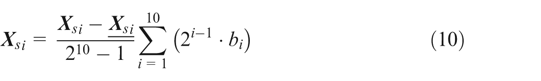
Step 1 is to encode and decode the chromosomes
The variable encoding is to convert the design variable
Step 2 is to initiate a population
A randomly generated population in binary system is assumed to include p individuals.
Step 3 is to define the individual evaluation
In fixturing sequence s, the deviation between the predicted clamping deformation and the corresponding simulated clamping deformation can be obtained as the prediction error

where p is the number of the chromosome
Step 4 is to perform genetic operations
Genetic operation mainly includes the selection, crossover, and mutation. Here, the roulette wheel is generally chosen as the selection operation. According to equation (11), the fitness value of populations can be summed up as
Denote
The choosing process of a chromosome for a new population is shown in Figure 4(a). The selected individual may either directly pass its genes on to the next generation or intercross some genes to a new individual in the next generation.
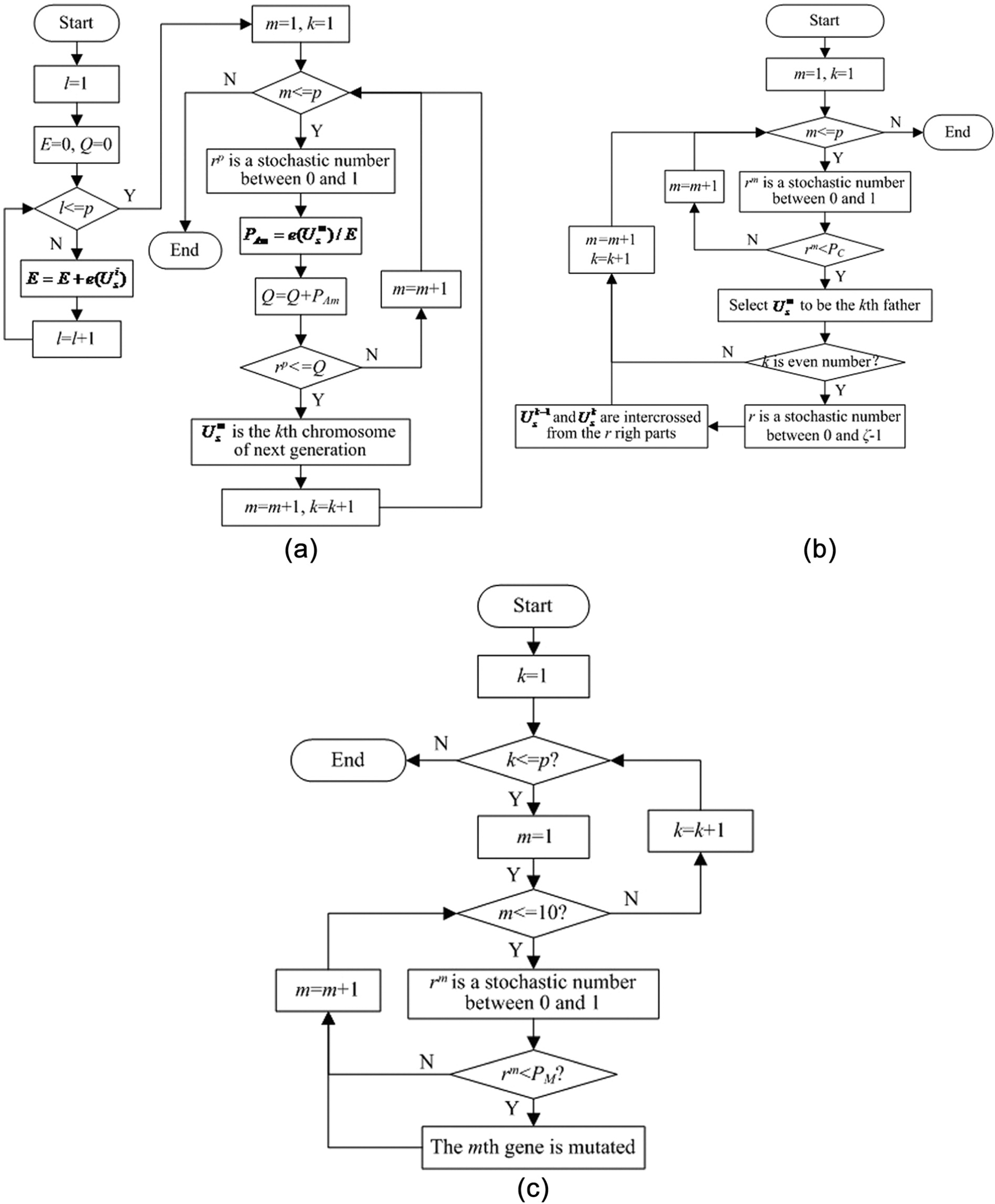
Flowchart of genetic operation: (a) roulette wheel selection, (b) single-point crossover, and (c) basic mutation.
The crossover operation can usually be realized by the single-point crossover operator. Here, PC is assumed to be the crossover probability (i.e. the PC of chromosomes are averagely intercrossed). And then, the flowchart can be plotted in Figure 4(b). The intercrossed individual can either enter the next generation directly or mutate a new individual in the next generation.
For the individuals with the binary genetic code, the mutation operation is to exchange the genetic code with one other with a small probability, that is, convert 0 to 1 and 1 to 0. Its aim is to avoid the local optima from happening premature convergence in the genetic algorithm. When the mutation probability PM is ordinarily assigned for a small value, the flowchart of basic mutation can be illustrated in Figure 4(c).
Step 5 is to judge the termination condition
Genetic algorithm is a kind of search heuristic based on probability-driven approach and has been widely implemented to solve the optimization problems. It can gradually approach and come close to the optimal solution when the individual evolution is iteratively carried out. Therefore, it is necessary to set the termination conditions for the generational process. Here, the number of iterations is given as a constant T. When the number of individuals with the same fitness value equals T, the algorithm terminates and provides a feasible optimal solution.
Optimization technology of fixturing layout
It is significant for the machining accuracy to control the clamping deformation of the thin-walled workpiece. The clamping deformations can be usually controlled by optimizing the fixturing layout. From the view point of mathematics, in order to control the clamping deformation, an optimal fixturing layout must be determined to obtain the minimum clamping deformation of the thin-walled workpiece.
Optimal model
Assuming that Ω is the number of nodes,
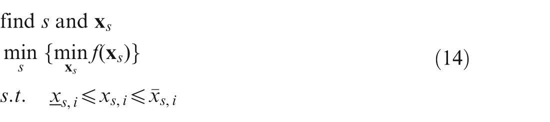
where
Solution technology
In the optimal process of fixturing layout for the thin-walled workpiece, it is difficult to obtain the complex relationship between the design variables and the objective function as well as the gradient of the objective function. Accordingly, the genetic algorithm related to in the “Solution technology” section would be a good choice to solve the optimal model of fixturing layout for the thin-walled workpiece. However, two differences between equations (9) and (14) are worth noticing. The first is the variety of their decision variables. The decision variable in equation (9) is the initial weights and thresholds, whereas the decision variable in equation (14) is the fixturing layout.
Another difference is their individual evaluation functions. In equation (14), f (
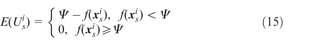
where Ψ is a large numerical value which is pre-specified according to the objective function values of each generation.
As stated above, the neural network–based genetic algorithm can further be constructed for fixturing layout of thin-walled workpiece, as shown in Figure 5.
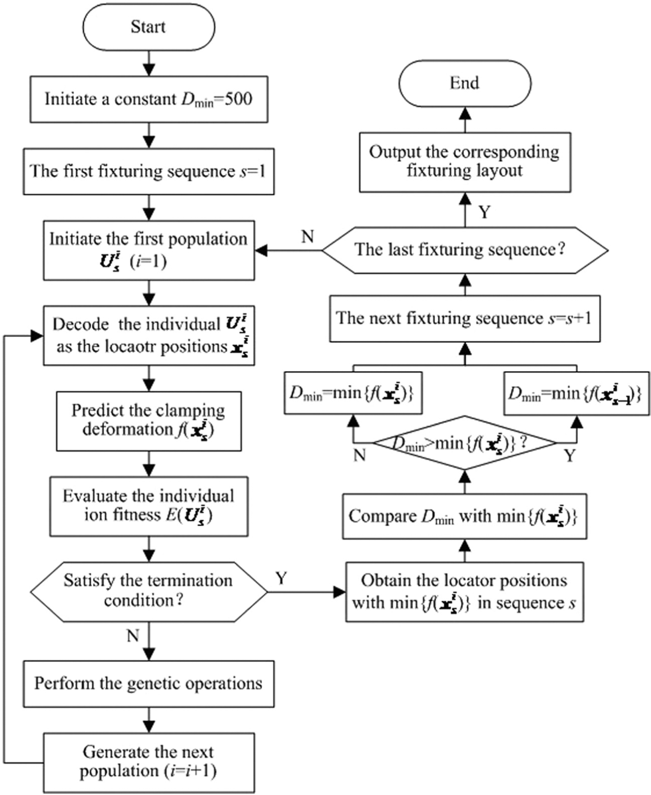
Flowchart of genetic algorithm based on neural network.
Numerical tests and experiments
To illustrate the proposed method, the first example shows the simulation strategy for the clamping deformation of aeronautical thin-walled structure with frame type. The agreement of the simulated results with the experimental data is done to validate the finite element model. The second example is employed to demonstrate the application of the presented “analysis—prediction—control” method of clamping deformation illustrated in Figure 5. The predicted results are verified by comparing the predicted values with the simulated ones.
Finite element analysis of workpiece deformation
The material of thin-walled workpiece with frame type is aluminum alloy 6061-T6 with Young’s modulus Ew = 70 GPa and Poisson’s ratio νw = 0.334. The outer dimensions of the workpiece are 153 mm×127 mm×76 mm with a uniformed wall thickness of 7 mm.
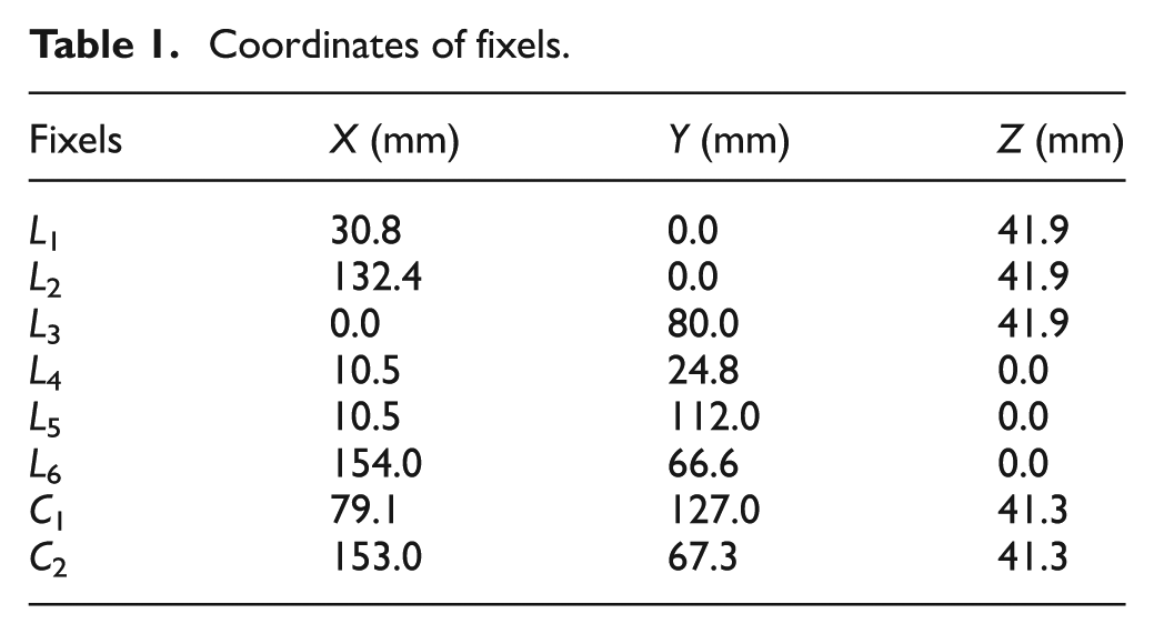
The fixturing layout of the thin-walled workpiece is shown in Figure 6. Three locators L4, L5, and L6 are placed on the primary locating reference, two locators L1 and L2 on the second locating reference, and the sixth locator L3 on the third locating reference. Two clamps C1 and C2 are used to hold the workpiece against external force. Planar-tipped locators and clamps are made of hardened steel AISI 1144 with Ef = 206 GPa and νf = 0.296. The dimensions and heights of locators are 12.72 and 6.4 mm, respectively, and those of clamps are 8.74 and 6.4 mm, respectively. The coordinates of fixels are listed in Table 1.
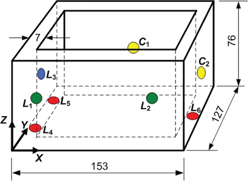
Diagram of workpiece fixturing.
Coordinates of fixels.
According to equations (1)–(3), the finite element model is constructed using ABAQUS, as shown in Figure 7. All components in the finite element model are assumed as isotropic elastic bodies. The 10-node tetrahedral element C3D10 is used to mesh all solid bodies. Contact between the workpiece and fixels is simulated by the quadratic surface-to-surface contact element with the static friction coefficient μ = 0.18 between the workpiece and fixels.

Finite element model.
To precisely simulate the locators being rigidly fixed in appropriate place, the surface of each locator tip opposite to the contact is restrained in all three translational degrees of freedom (DOFs). A uniformly distributed pressure is applied over the surface of both clamps in opposite contact to simulate the desired clamping force. When the clamping forces is able to, respectively, supply the workpiece with 250 and 350 N, the clamping deformations at two points C1 and C2 can be simulated, as plotted in Figures 8 and 9.
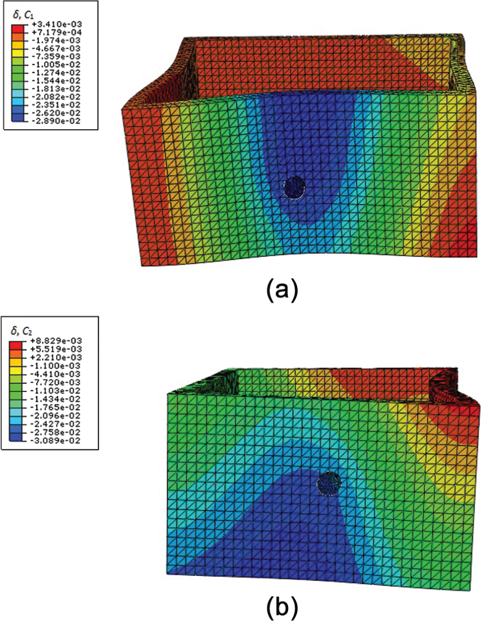
Clamping force of 250 N: (a) deformation of C1 and (b) deformation of C2.
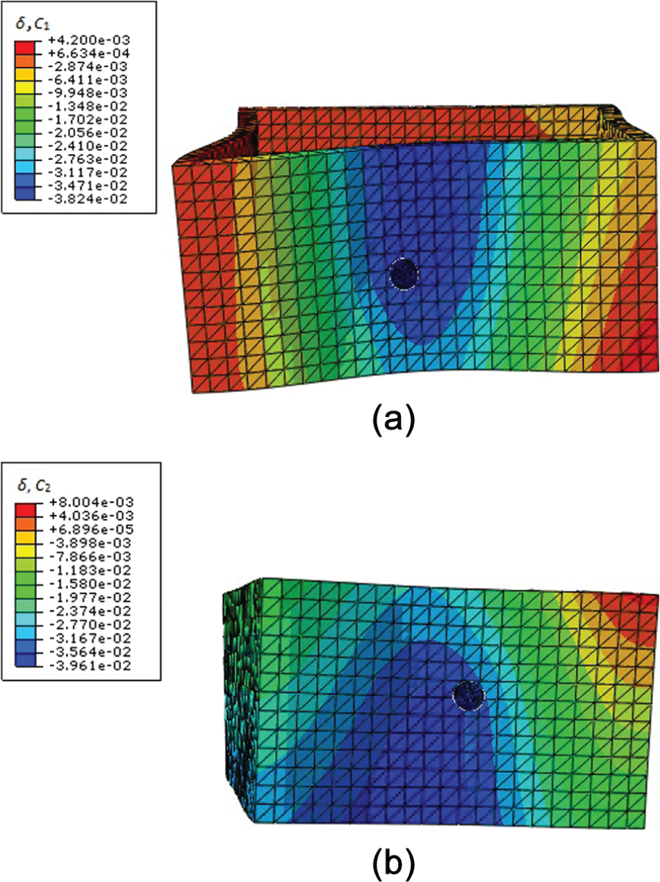
Clamping force of 350 N: (a) deformation of C1 and (b) deformation of C2.
Experimental data were measured to assess the validity of the simulated results. According to Siebenaler and Melkote, 9 the test fixture was assembled using six locators and two clamps, as shown in Figure 10. Locators L4, L5, and L6 were screwed directly into a 15-mm-thick steel base plate, and the other locators L1, L2, and L3 were screwed into steel support blocks which were fastened to the base plate. The two clamps C1 and C2, which were fastened to the base plate via steel support blocks, were actuated by a hydraulic hand pump. The clamping deformation at each point was measured using an eddy current proximity probe. Average deformation results over five trials for each point and load pair are given in Table 2.
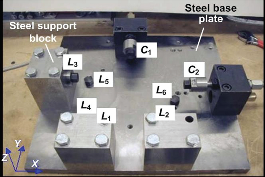
Test fixture.
Comparison of simulated results with experimental data.
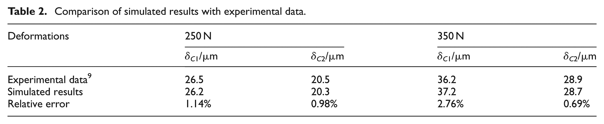
It is known from Table 2 that the maximum relative error of the simulated results is not more than 3% from the experimental data. The even amounts show that the established finite element method can be efficiently used to analyze the clamping deformations of the thin-walled frame-shaped workpiece.
Optimization of fixturing layout
As shown in Figure 11, the fixturing layout consists of four locators (L1, L2, L3, and M) and three clamps (C1, C2, and C3). The workpiece is a thin-walled part with outer dimensions of 200 mm×100 mm×30 mm and thickness of 5 mm. According to the “3-2-1” locating principle, the support plate M constrains 3 DOFs of the workpiece, that is, the translational DOF T Z along the Z-axis and the rotational DOFs R X and R Y around the X- and Y-axes. The support pins L2 and L3 are used to constrain the translational DOF T Y along the Y-axis as well as the rotational DOF R Z around the Z-axis. Finally, the translational DOF T X along the X-axis is restricted by the support pins L1.
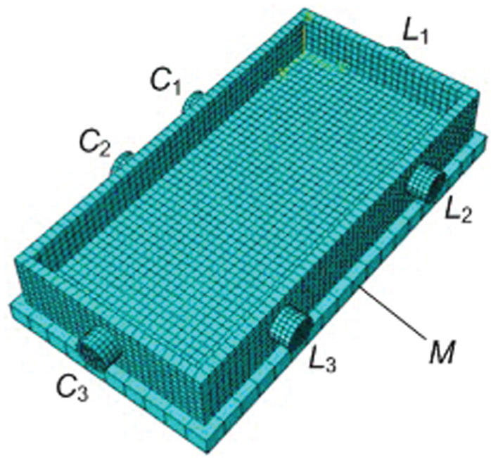
Finite element model of fixturing layout of workpiece.
In order to resist the external loads during the machining process, three clamps C1, C2, and C3 produce clamping forces against the workpiece. The locators have a radius of 8 mm and a height of 10 mm. The clamps are of equal radius and height as the locators. The clamps C1, C2, and C3 are prescribed by the pressures of 20, 20 and 30 N, respectively. Here, three clamps, whose coordinates are
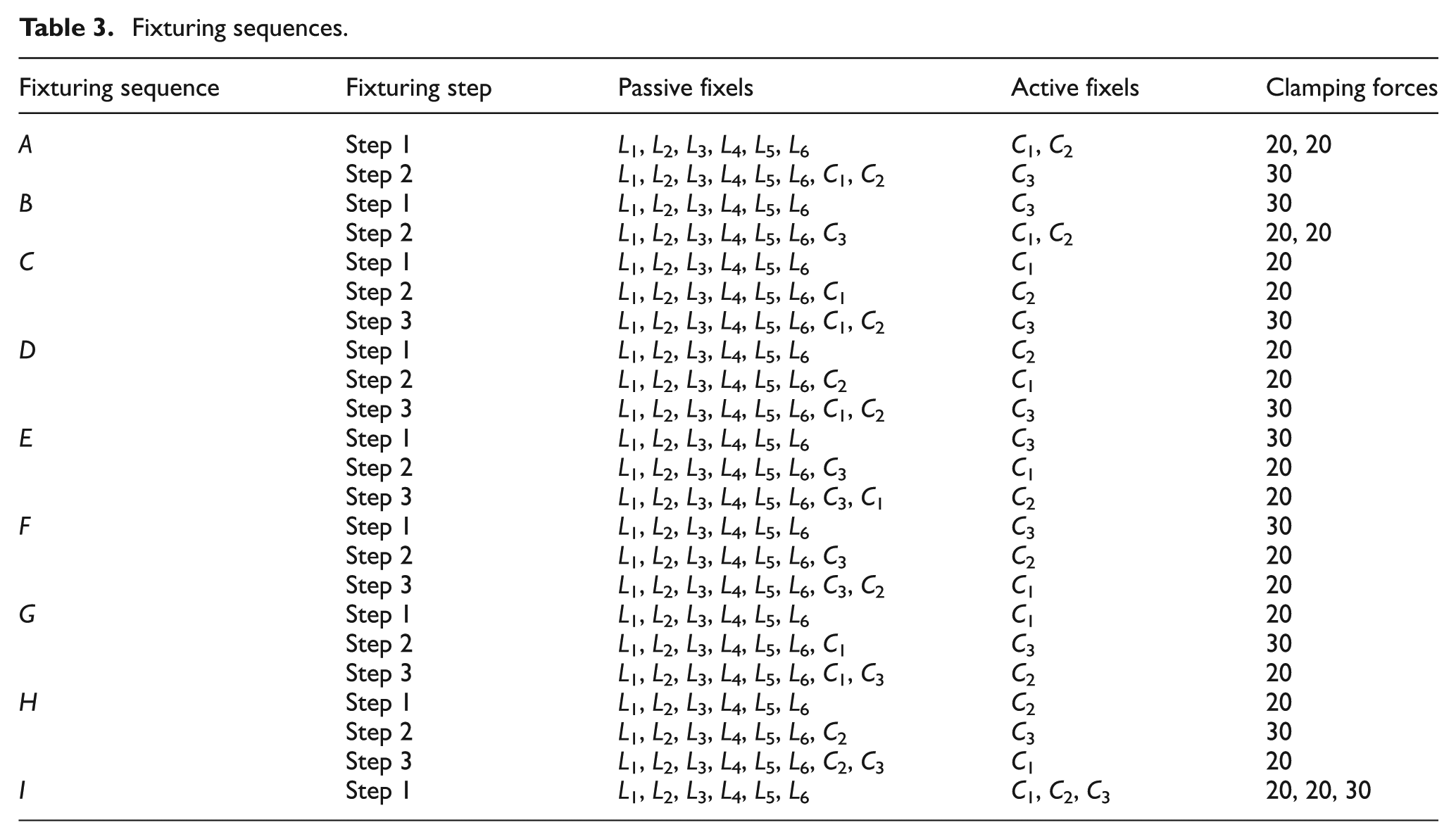
The fixturing sequences are listed in Table 3 for C1, C2, and C3. Effects of different fixturing sequences on clamping deformations will be examined.
Fixturing sequences.
Deformation analysis
The workpiece is made of aeronautic aluminum alloy 7050-T7451 with Young’s modulus Ew = 70 GPa and Poisson’s ratio vw = 0.3. Because planar-tipped locators and clamps including L1, L2, L3 and C1, C2, C3 have far greater stiffness than the thin-walled workpiece, they can be thought of as rigid bodies. The static friction coefficients between the workpiece and the fixels are μ = 0.3. The 8-node hexahedron element C3D8R and 4-node tetrahedral element R3D4 are used to mesh the workpiece and fixels, respectively. The contact between the workpiece and fixels is defined as the quadratic surface-to-surface contact elements. With these conditions, the finite element model is established for fixturing layout of the thin-walled frame-shaped workpiece, as shown in Figure 11.
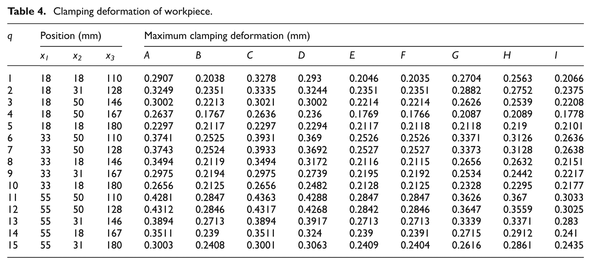
In connection with equations (1)–(3), the load step is defined for each fixturing sequence according to Table 3. Computation can sequentially be carried out to solve the finite element model. Here, C1C2 denotes the inner wall of the frame where clamps C1 and C2 are contacted with the workpiece. Because the maximum clamping deformation occurs at C1C2 in the Y direction, emphasis of investigating the clamping deformation is on C1C2. Table 4 lists the maximum clamping deformations.
Clamping deformation of workpiece.
Deformation prediction
Under the condition of the given magnitude and placement of the clamping forces in each fixturing sequence, according to the Figure 2 and equation (4), the neural network structure can be determined to have u = 3 neurons (i.e. the position x1, x2, and x3 of three locators L1, L2, and L3) at the input layer, w = 1 neurons (i.e. the maximum clamping deformation) at the output layer, and v = 7 neurons at the hidden layer.
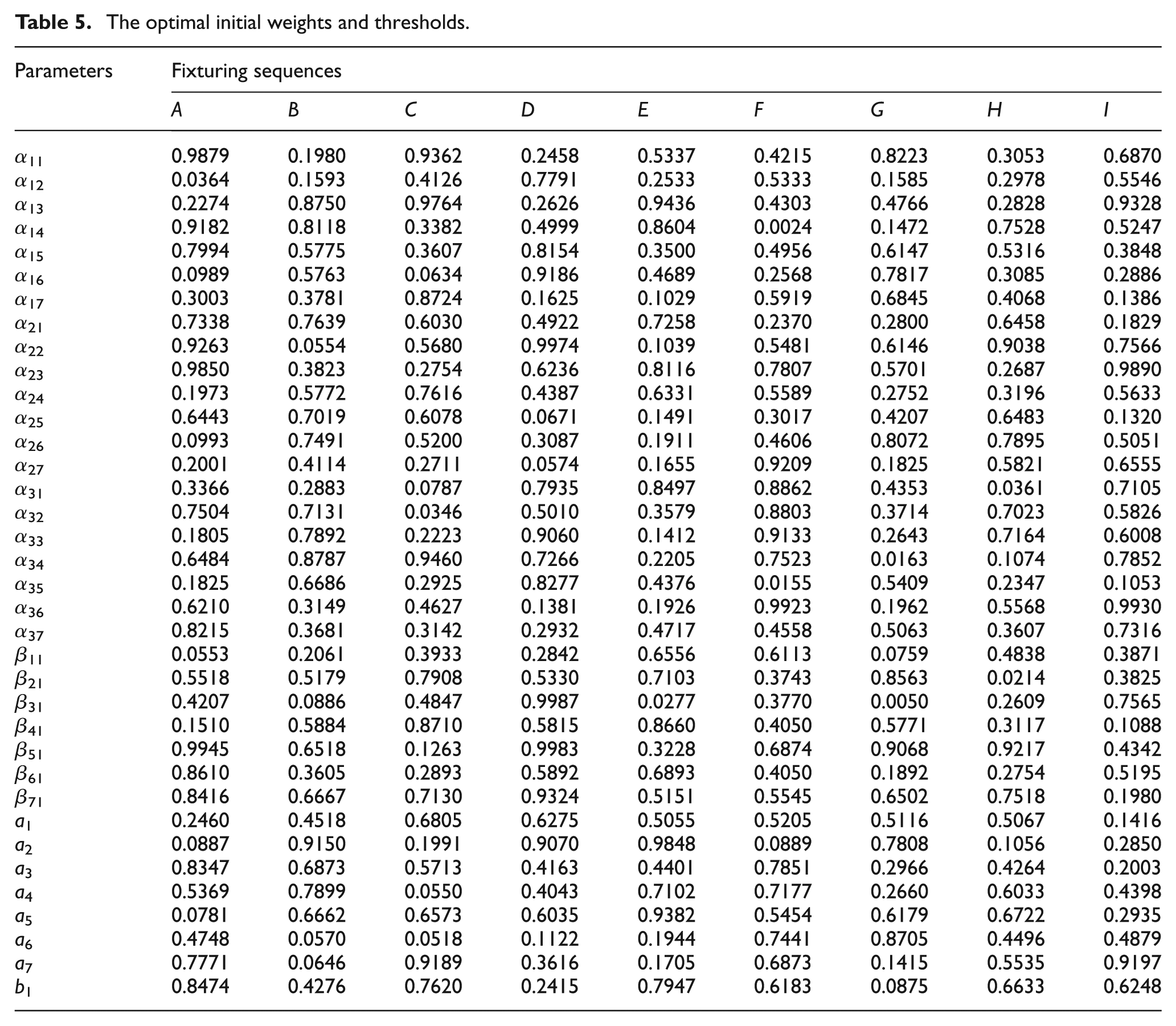
The orthogonal experimental design method, here, is adopted to generate the sample points for x1, x2, and x3 in each fixturing sequence. The corresponding training samples are calculated by the finite element method, as listed in Table 4. Thus, the genetic algorithm, whose parameters, respectively, are the individual number p = 20, the crossover probability PC = 70%, the mutation probability PM = 3%, and the iteration number T = 40, can solve equation (9). This obtains the optimal initial weights and thresholds for the neural network, as shown in Table 5.
The optimal initial weights and thresholds.
According to equation (7), 15 training samples in the fixturing sequence A can be normalized as inputs to the neural network. If the learning rate and the learning error were, respectively, given as 0.05 and 1.0e–5, the training process stopped at the 63rd step, as shown in Figure 12.
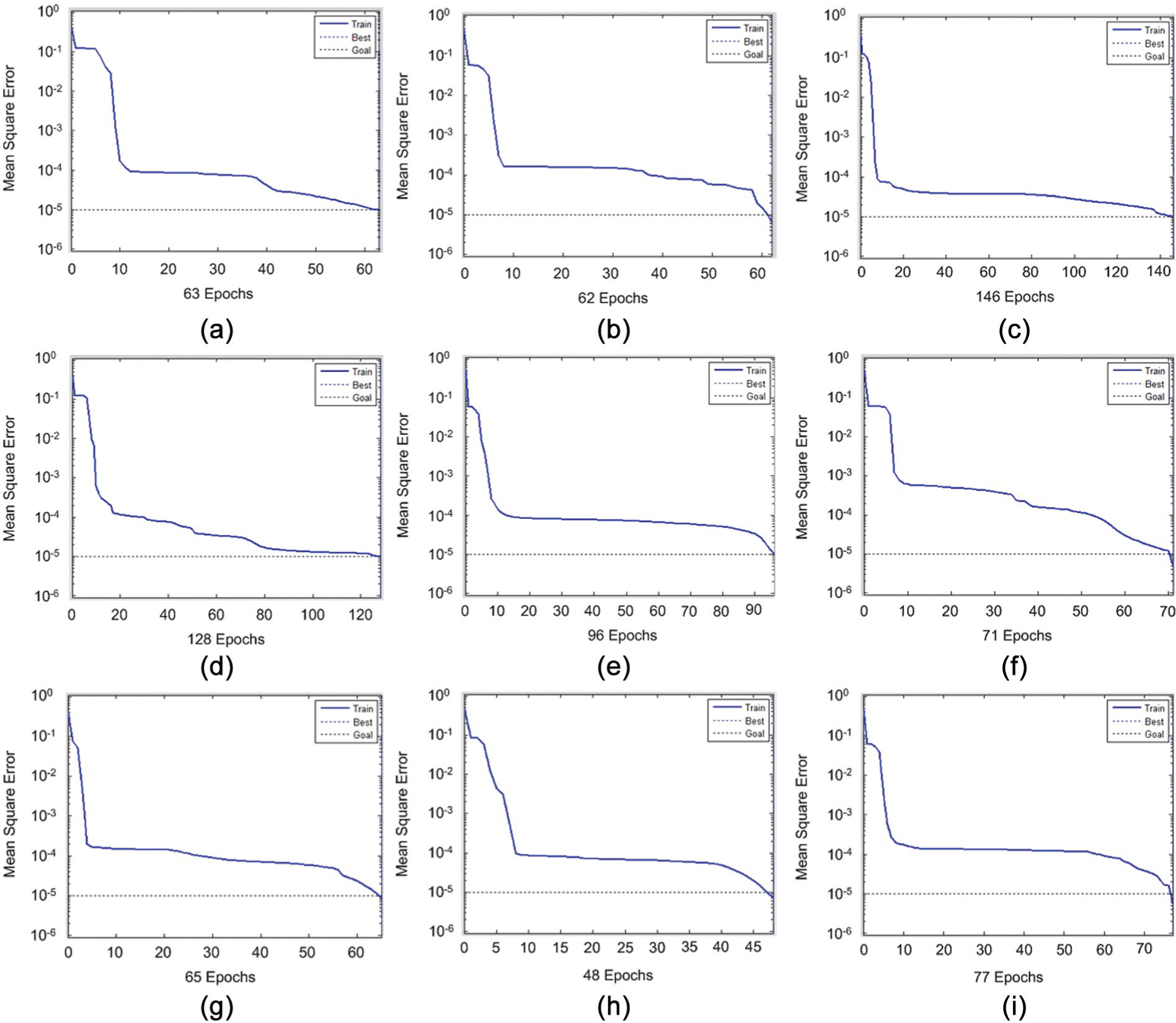
Training of neural network: (a) sequence A, (b) sequence B, (c) sequence C, (d) sequence D, (e) sequence E, (f) sequence F, (g) sequence G, (h) sequence H, and (i) sequence I.
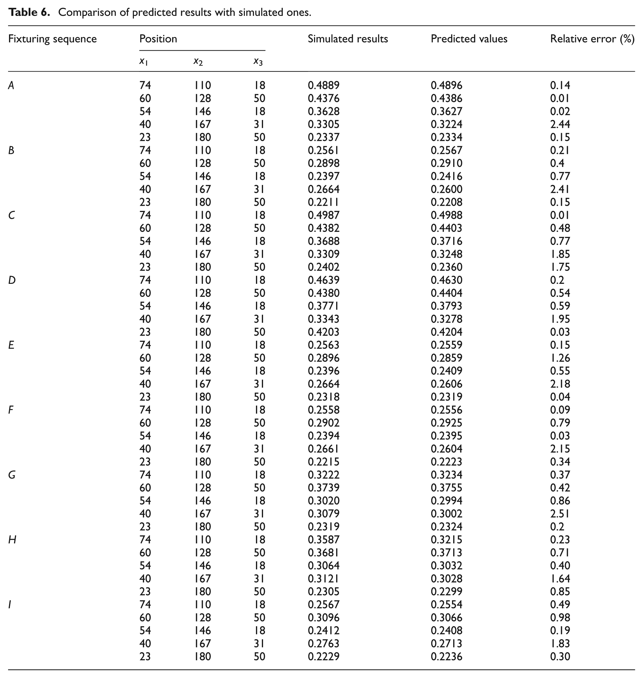
In the same way, the training of neural network can also be carried out for the other eight fixturing sequences. The training processes last from 48 steps to 146 steps, and they can quickly be converged. Finally, equation (6) is performed to predict the clamping deformation caused by arbitrary fixturing layouts. Table 6 lists the predicted results and the corresponding simulated values, and the relative error between them is within 3%. The above agreement demonstrates that the proposed neural network prediction method is effective.
Comparison of predicted results with simulated ones.
Deformation control
When the genetic parameters are given as the individual number p = 20, the crossover probability PC = 70%, the mutation probability PM = 5%, the iteration number T = 40, and the evaluation parameter Ψ = 200, the genetic algorithm shown in Figure 5 is carried out for the locator positions in fixturing sequence A, and the results are shown in Figure 13. The iterative process is performed with more than 20 generations, but the maximum clamping deformation is always close to 0.2300 mm. At the moment, the optimal locator positions are thought to be x1 = 18, x2 = 180, and x3 = 18 mm.
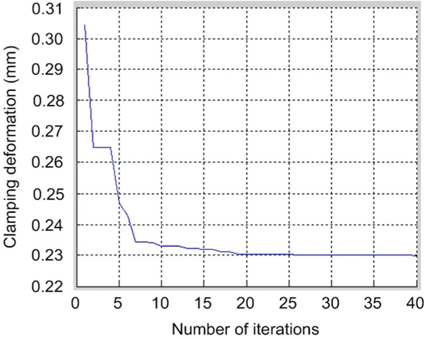
Convergence process of genetic algorithm.
Table 7 lists the maximum clamping deformation and the optimal locator positions for nine fixturing sequences. In all fixturing sequences, the fixturing sequence B has minimum clamping deformation of 0.1760 mm. In connection with equation (7), it is known that the optimal fixturing layout must be determined as the following fixturing parameters for given magnitudes and placements of three clamping forces: three locator positions are, respectively, x1 = 18, x2 = 167, and x3 = 50 mm, and the application sequence of three clamps is B.
Maximum clamping deformation of fixturing sequence.
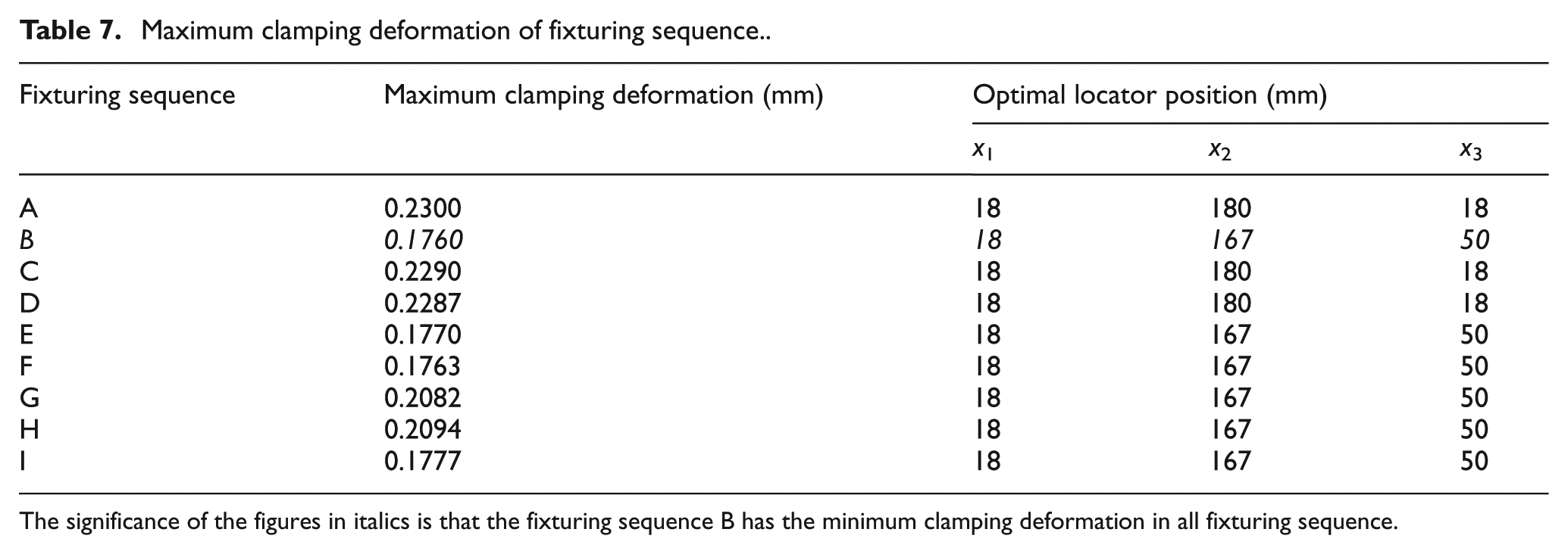
The significance of the figures in italics is that the fixturing sequence B has the minimum clamping deformation in all fixturing sequence.
Conclusion
The BP neural network has high precision and good generalization ability. Based on the finite element model of fixturing layout for thin-walled frame workpiece, the nonlinear logic relationship between the clamping deformation and fixturing layout is effectively established through the excellent learning ability of BP neural network. The experiment shows the relative error of the simulated results with the experimental data is less than 3%. Moreover, the predicted results are in agreement with the simulated values. In summary, the prediction accuracy is more than 90%, and it means the proposed prediction method can properly calculate the clamping deformation of thin-walled frame workpiece in an arbitrary fixturing layout. Next, the optimal model is suggested to minimize the clamping deformation. The genetic algorithm is adopted to solve the optimal model for the fixture layout of thin-walled frame workpiece. Finally, two examples are employed to demonstrate the application and availability of the “analysis—prediction—control” method. The presented method not only controls the clamping deformation for thin-walled workpiece but also increases computational speed by the prediction method more than that of the finite element method.
Scope for future work
Under the condition of static loads, this work can obtain the optimal fixture layout for minimizing the workpiece deformation. The effect of the dynamic machining forces on the workpiece deformation is omitted in this work. So this work can be extended to optimize a fixturing layout for the workpiece in the entire machining process.
Footnotes
Appendix 1
Declaration of conflicting interests
The authors declare that there is no conflict of interest.
Funding
This work is supported by the National Natural Science Foundation of China (Grant No. 51165039, Grant No. 51465045), Aeronautical Science Foundation of China (Grant No. 2013ZE56019), National Natural Science Foundation of Jiangxi Province (Grant No. 20142BAB206018, Grant No. 20142BAB206023), and Basic Research Plan in Shenzhen City (Grant No. JCYJ20140509174140668).