
Abstract
Closed-cell aluminium foam, a porous structure, is effectively used for insulation, structural applications, packaging and filtering. Cutting of aluminium foam with the help of fibre laser is an efficient method due to the inherent advantages of fibre laser. Laser cutting of aluminium foam was carried out using a 2-kW fibre laser system for varying process parameters and different assist gas environments. Use of different foaming agents results in the generation of gas-filled pores. During the laser cutting process, the interaction of these gas-filled pores with assist gas results in in-situ reactions, generating different kerf quality. This interaction effect of foam cutting was reported using optical, metallurgical and thermal analysis. Thermal cycles were recorded to understand the occurrence of different in-situ reactions. From the temperature signal for different assist gases, oxygen showed the highest temperature, followed by nitrogen and argon. Argon assist gas gave minimum kerf width, while nitrogen assist gas produced minimum dross. Elemental and phase analysis showed the presence of new compounds and intermetallics in the cut section that stipulated the occurrence of in-situ reactions during the cutting process. The internal pore surface showed the presence of spatter in case of oxygen, while nitrogen and argon gas environment showed relatively less pore-clogging.
Keywords
Introduction
The recent advancements in the field of material science and manufacturing highlight the applicability of a material that can decrease the cost and increase the potential applicability in various fields. One such material that is taking attention of the industry is metal foams. They are composite materials having two phases or parts: one is the bulk metal part that constitutes the wall or boundary, and other is the liquid or gas-filled part that represents the pores. The metal foams mainly consist of three types: closed-cell, open-cell and sandwich closed metal foams. The pores are interconnected in case of open-cell metal foams, while they are isolated in case of closed-cell metal foams.1–5 One of the exciting features of such metal foams is that the property can be easily tailored using size, position and orientation of the pores. Because of such flexibility, the metal foams have a vast application area from bioengineering to automobile, batteries, heating systems and structural applications to name a few.6–10 Some specific applications include battery case for electric cars, the floor of waggons, powerhead cover. 6 In defence, foams find applications in blast protection and ammunition hoods. Aluminium foams have automotive applications like generic crash box structures and safety bumpers of the front end. 9 Other practical applications of metal foams include telescopic lifting system, platforms for milling machines and tooling, prototypes for rocket adaptor, bicycle crank arm prototype and cookware. 10
Laser cutting process is an established and one of the cleanest cutting techniques of material where a focused laser beam thermally generates a cut without any physical contact between the cut surface and the laser source. The laser cutting of metals is one of the most common applications of laser material processing in industries and research.11–16 A substantial amount of literature is present for cutting of various metals like steel,17–19 titanium,20,21 aluminium22,23 and other metals. Past research studies helped in applying the laser cutting process for metal foams to enhance its applicability in various other fields.
Machining of metal foams is critical to increase its potential applications, but metal foams offer some challenges which act as a bottleneck for their machining. These challenges include cell wall ruptures, fracture of the cells due to vibrations in mechanical processing. Therefore, cutting of the complex profiles in metal foams became difficult with contact-type mechanical process. Laser cutting of foam, being a non-contact-type process, is advantageous as it prevents the deformation of the pore cell wall, foam failure and rupture which take place in the mechanical cutting process of foams.24,25 Laser also provides a solution for fast and efficient cutting of complex geometries. These advantages resulted in exploring the possibilities of laser cutting of metal foams. Simulations were carried out to understand how the metal foam cutting is different from the bulk metal cutting process.26,27 Morphological evaluations were performed, respectively, on the kerf part with different laser process parameters. 14 Laser drilling processes were carried out on fragile foams to understand that the cutting could be performed. 28 Various geometries were cut on the foams, and their cut zones were characterized26,29 for the presence of stress and dross. The study showed that during cutting of foam, the laser successfully cuts the material with little or no deformation to the sphericity of the foam pores. However, the dross attachment remains an issue that causes the pore shape and size to change. Different cutting gases were used to perform cutting action of foams,30,31 and the results showed that argon performs better than the other cutting gases. The presence of oxides and nitrides on the cut section was also reported in the previous research studies. Laminar striations are ubiquitous phenomena observed in the cutting of bulk metals. The kerf quality obtained after cutting showed the striation marks of molten metal flow. Previous research18,30 showed that the channel developed while cutting of bulk metal provides a well-defined and constricted path to the flow of assist gas. However, the geometry of the metal foams did not provide this channel continuity to the flow of the molten pool and the gas (refer Figure 1). Therefore, the gas pressure effect during cutting on bulk ad metal foams varies significantly due to porous structures present in metal foams.
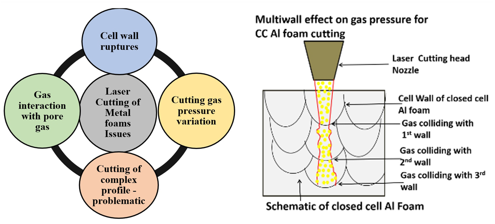
The challenges and issues during laser foam cutting of closed-cell aluminium foams.
Foams contain different gases in its pores which get trapped during its manufacturing process. 5 The gases in the pores also react with the assist gases during laser cutting, and they affect the cutting process. Also, the interaction of the cutting gas with multiple cell walls results in reduced gas pressure and turbulence, thereby reducing the gas jet effect. The mixing of the cutting assist gas and the pore gas, at high temperature, promotes various types of reactions in the laser cut zone (Figure 1). Previous research did not address the interaction behaviour of the assist gas with the pore-trapped gas in a metal foam. Also, the chemistry of the effect was not reported in the past. This aspect is critical to understand the cut quality of closed-cell metal foam.
The laser cutting process of aluminium foams and aluminium bulk sheets differs distinctly due to two phenomena. First, the pores present in the structure of the foams causes the assist gas to deviate from its kerf path, causing turbulent motion, reduced gas pressure and affecting the cut quality. Second, the trapped gases in the pores also affect the cut quality as the high temperature of the cutting zone assists exothermic reactions leading to the formation of various compounds and precipitates between different phases of molten material, assist gas along with trapped gases. These compounds and precipitates later change the viscosity of the melt and thus affect the cut quality. The reported work acts as one of the fundamental approaches to report these form of interactions.
Present research systematically analyse the effect of the different assist gases that are used during laser cutting of aluminium foams emphasizing on how these gases interact with the gas-filled pores of the closed-cell metal foams. The in-situ reactions were detected using non-contact-type infrared pyrometer, and the maximum cutting temperature was determined. The temperature signal obtained was analysed with various characterization techniques in order to understand how the cutting process of foam got affected due to thermal interactions. Experiments were carried out using nitrogen (N2), argon (Ar) and oxygen (O2) gases at different process parameters. The cut quality (kerf width) was analysed using optical, microstructural and chemical analysing techniques.
Experimental details
Materials
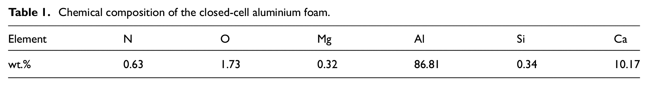
Closed-cell aluminium foam of dimension 125 × 30 × 10 mm 3 is used for the experimental work. The aluminium foam has a density of 0.35–0.7 g/cm3, porosity of around 60%–70% and the pore diameter is around 2–5 mm. The chemical composition of the material is as per Table 1. The manufacturing of the foam consists of the addition of the calcium (1.5–3 wt.%) in aluminium at around 953 K, which after stirring action increases its viscosity. Then, a foaming agent TiH2 (1.6 wt.%) is added to release hydrogen gas which gets trapped in the pore form during the cooling process. 5 The formation of Al–Ca phase occurs within the Al matrix, and so Al + Al4Ca system coexists as per the phase diagram of Al–Ca system. 32 The formation of Al4Ca is the result of the peritectic reaction between Al and Ca as follows

ΔHf = −41.8 ± 6 kJ/mol and ΔGf (Al4Ca, S, T) = −18,702 + 4.591T J/mol.32–34
Chemical composition of the closed-cell aluminium foam.
Methods and experimentation
A Yb-doped 2-kW fibre laser (IPG make, model: YLR 2000) with five-axis CNC (Sinumerik operating system) having a wavelength of 1.07 µm, nearly Gaussian beam profile, working in both continuous and pulse mode, was used for the experimentation. The laser melts the material and gas jet ejects out the molten materials to perform the cutting. Based on the result of previous research, 14 power was kept constant at 1200 W while changing scan speed (400, 700, 1000 mm/min) and gas pressure (6 and 10 bar) as input parameters to understand the effect of laser cutting operation on kerf quality and kerf chemical composition of the foam. The cutting gas nozzle had 0.5-mm focal spot diameter and 3.5-mm focal point position outside the nozzle tip. The nozzle was set at 1.5-mm stand-off distance from the foam surface so that the focal point lies 2.0 mm within the foam. A coaxial jet of nitrogen, argon and oxygen gases was used as the cutting assist gas. Infrared pyrometer (Micro-Epsilon, model: CTLM-2HCF3-C3H) was used for capturing the thermal cycle in the laser cut zone. The pyrometer has a capture zone of 0.7 mm and 1-ms data acquisition time at a 1.6 μm wavelength which can record a temperature between 385 °C and 1600 °C. A notch filter of 1.07 μm was used to block the fibre laser wavelength from interfering in the thermal history data. A typical signal received from the laser cutting process is shown in Figure 2. As the laser beam reaches towards the pyrometer spot, the temperature signal indicates that the temperature rise takes places in different cycles (Figure 2). The signal is not very sharp and prominent as it occurs for different laser processes. The signal varies as the kerf generated during the laser cutting process changes the pyrometer spot focal position. Also, the internal reflections within the cut zone cause variable signals during the cutting operation. Nevertheless, the maximum temperature signal is the signal that corresponds to the position when laser and the pyrometer are coincident. This maximum temperature signal used to analyse the thermal behaviour of the actual cutting process. From Figure 2, ‘A’ is the zone when the laser cut zone approaches the pyrometer focal position. ‘B’ is the coincident point location, while ‘C’ is the retreating zone where laser cuts away from the pyrometer position. The maximum temperature at B is the value that is used to compare the maximum temperature generated during the experiment.
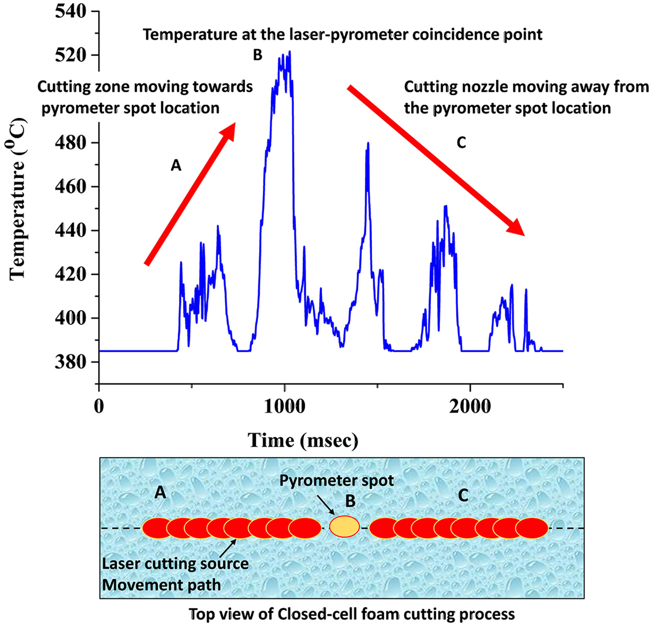
Typical thermal signal obtained and the top view of the signal acquisition position on the Al-foam surface.
Figure 3 shows schematic of the laser cutting operation performed. Three sets of the experiments were performed similarly, and the results were presented as an average of them. After the experiment, the cut sections were carried for further characterisations. No post-treatment of the cut section was performed to maintain the integrity of the morphological and chemical behaviour of cut section during the cutting process.
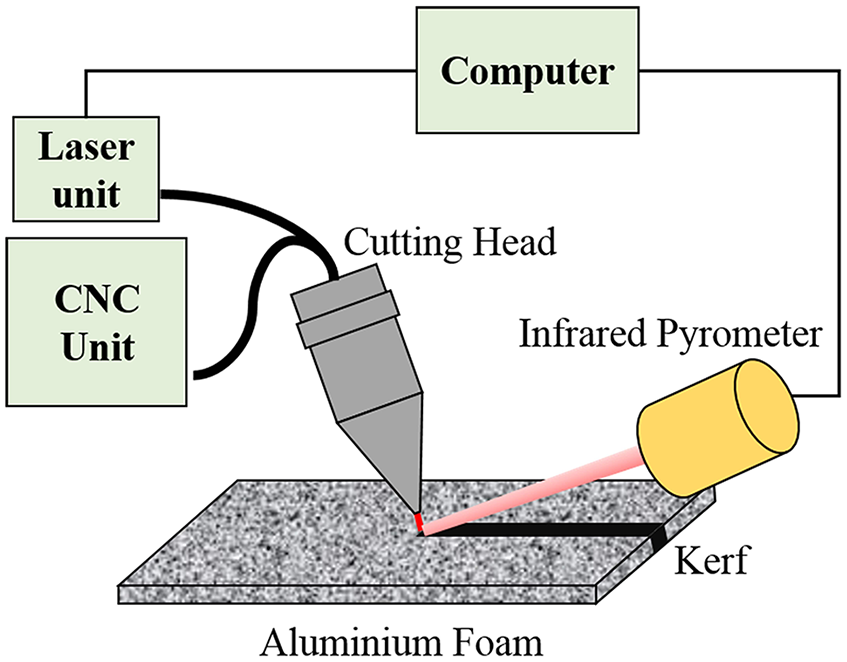
Schematic of the laser cutting operation along with infrared pyrometer for temperature detection.
Optical microscopy (Zeiss Axio Zoom.V16) was used for kerf width and taper percentage measurement for the different assist gases. Secondary electron images from SEM (make: Zeiss, model: EVO 60) were analysed to understand the effect of in-situ reaction on the top and bottom kerf quality. Energy dispersive X-ray spectroscopy (EDS) (model: EDAX-Ametek, software: TEAM) and X-ray diffraction (Model: PANalytical Empyrean, software: Xpert high score plus) were used to analysis phase formation that took place in the cut section. Finally, the results of the kerf quality and temperature signals were analysed, and the effect of gases on the laser cutting of closed-cell aluminium foams was correlated and discussed.
Results and discussion
Morphological aspects of the kerf width after the laser cutting process
Figure 4(a) shows the top view of some of the laser cut sections, while Figure 4(b) shows a magnified view of the laser cut section. It was observed that the top kerf produced was free from dross, and a collinear cut was produced. Although some thin wall melting occurred (Figure 4(b)) which is very much evident for foam cutting process. The foam contains thin walls at some location which in case of laser interaction gets melted away owing to its high heat accumulation and less heat loss. It was also revealed that the top surface had a uniform kerf width while the bottom surface was relatively less uniform. Based on the physical morphology of the aluminium foam, it can be explained that the presence of discontinuous walls causes the gas pressure to get diffused (Figure 1), causing the bottom kerf to become less uniform.
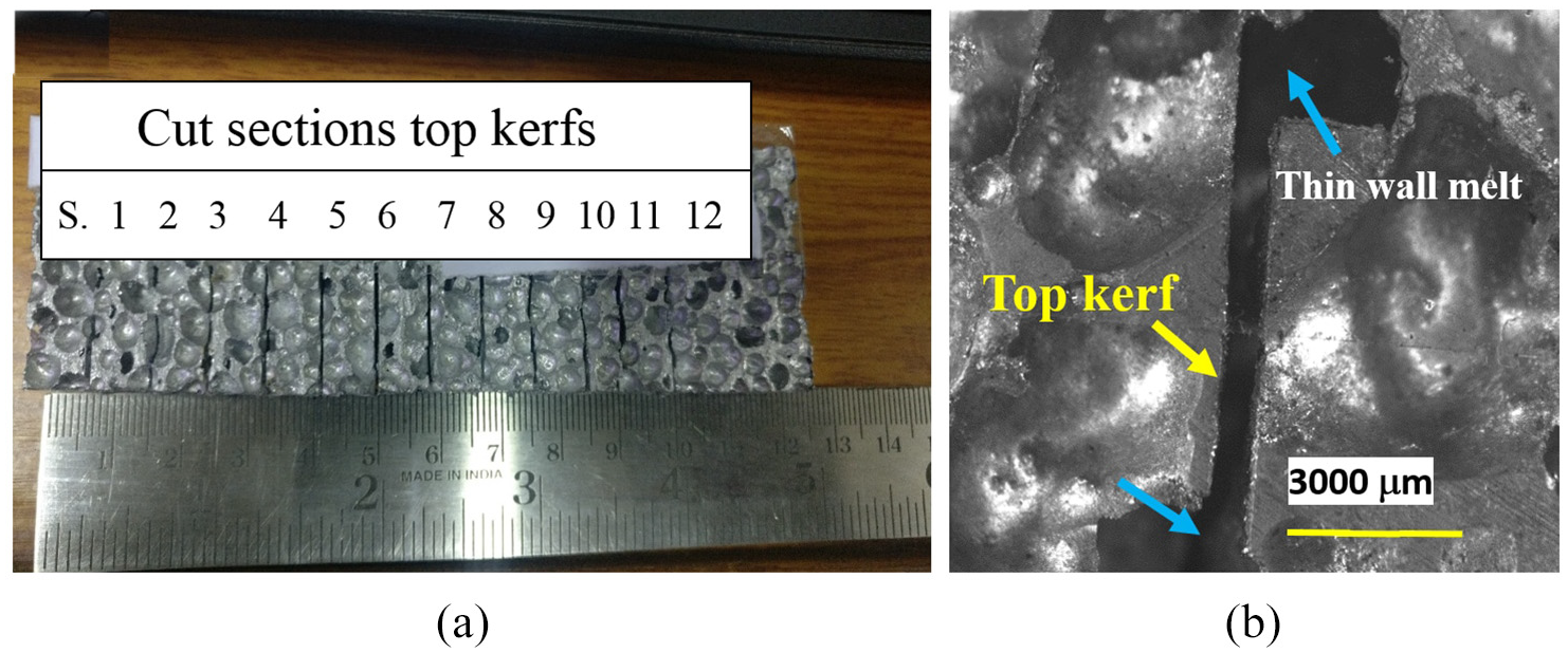
(a) Some of the laser cut samples and (b) top kerf showing the partial melt of the pore boundary.
Figure 5 shows the cross section of the laser cut zone for different gas environments which showed that there is no distortion of pore shape. The uppercut portion contains some striation marks, but the transition plane is not visible. The presence of multiple cell wall interaction generated turbulence in the gas flow that affected the directional striation marks generation. Again, the kerf quality is the best for nitrogen gas in terms of dross attachment and the attachment of melt particles. In Argon environment, relatively more dross was observed in the pore boundary than nitrogen. In the case of oxygen environment, the spatter produced in the oxidation process resulted in the explosive ejection of dross in all the directions. So, the striation marks are the least in this case, and the pore inner surface contained the remelted particles.
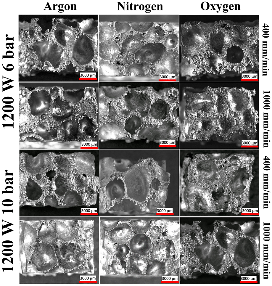
Cross section morphology of the laser cut zone with different assist gas.
The cross section of the cut zone was quantified for dross attachment using an image analysing technique. The quantification was carried out using ImageJ software. The pore boundaries were detected to calculate the pore area. Then, the dross attached inside the pores was segregated, and the dross area was calculated. Finally, the total area of the bulk material, including dross attached to pore inner surface, was calculated by subtracting them from the preselected total area of the cross section (refer Figure 6(a)). Figure 6(b) showed that considering the dross in the wall section as well as dross attached inside the pore surface due to spattering reaction, oxygen showed the maximum dross content followed by argon and nitrogen.
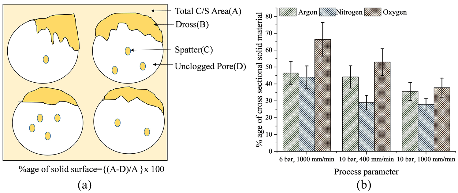
(a) Method adopted to quantify the dross attachment and (b) quantitative analysis of the dross attached for different assist gases.
Figure 7 shows the effect of scan speed on top kerf width at 1200 W with N2 assist gas at (a) 6- and (b) 10-bar gas pressure. Some thin wall melting occurred. The kerf width value directly depends on the amount of heat input in the cut zone.15,35 The increase in scan speed caused a decrease in kerf width due to lower heat input. However, a limiting condition always exists, where after a maximum scan speed, the through cutting process does not take place. In the present experimental condition, for 1200-W power, after 1000 mm/min, the through penetration was not observed. The kerf width varied from about 542 to 668 μm for argon, from 580 to 685 μm for nitrogen and from 665 to 750 μm for oxygen gas cutting. Thus, in terms of minimum kerf width value, argon showed the best result.
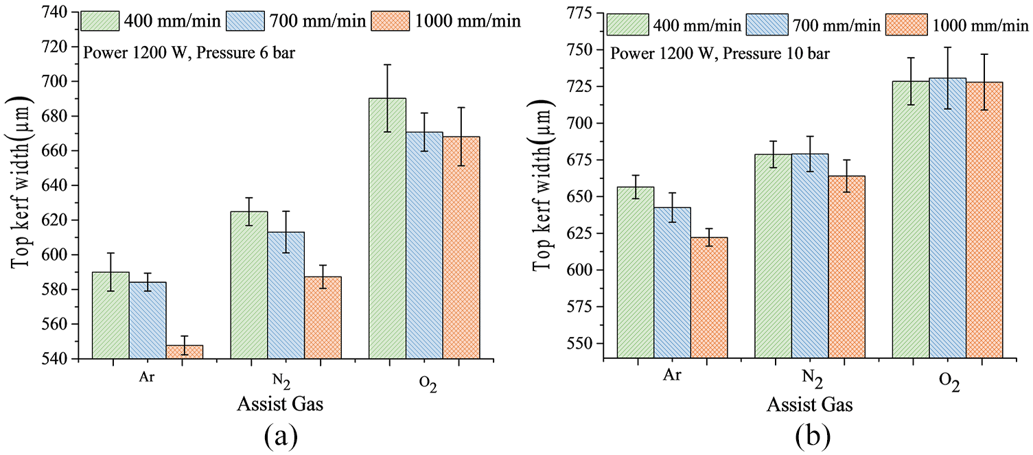
Effect of scan speed on top kerf width at 1200 W with N2 assist gas at (a) 6- bar and (b) 10-bar gas pressure.
Gas pressure in case of Al-foam plays a crucial role in terms of kerf quality. The dross attachment in case of 6-bar pressure was high than 10-bar pressure. It happened due to the inability of the dross to overcome the viscosity of the melt zone. As more dross remained on the cut zone, the kerf width was low for 6-bar pressure than the kerf width at 10-bar pressure. More gas pressure resulted in less dross with wider kerf width, while the lower pressure resulted in high dross with narrow kerf width. The higher gas pressure caused the melt portion to overcome the viscosity of the molten pool and removed the melt portion more efficiently.
The type of assist gas also affects the kerf width values. The in-situ exothermic reactions that take place within the cut zone add more heat along with laser heat input causing enhanced melting of the Al-foam. As a result, a wider kerf width was obtained. The variation in the kerf width value was maximum for oxygen, followed by nitrogen and argon, respectively.
Effect of H2-filled gas during the laser cutting process
Although the obtained kerf width showed variations in the width of the cut zone for different assist gases, yet the exact type of reactions that occurred in the cut zone was not revealed. In the laser cut section, the parent foam bulk material, assist gas and pore-trapped gas (H2) interact among themselves to cause the cutting action in the presence of laser heat source. The laser generating temperature in the range 500 °C–700 °C triggers various chemical reactions in the cut zone. During laser cutting of bulk sheet of aluminium, it was reported that the formation of nitrides and oxides results in an increase in viscosity and surface tension 36 of the melt. However, in case of foam cutting, the hydrogen trapped inside the pore reacts with N2 and O2 and results in the evolution of gaseous components like NH3 and H2O vapour, respectively. This, in turn, decreased the viscosity of the melt zone. Also, the high surface area present in the porous body provides a higher reaction rates and thus causes a difference in cutting process concerning bulk body. Figures 8 and 9 showed the secondary electron images of the laser cut section in argon and nitrogen gas environment, respectively. For a pressure of 6 and 10 bar, respectively, the amount of dross attachment was maximum for 6-bar pressure. The top kerf width showed a lower amount of dross than bottom kerf width. The amount of dross is less for nitrogen environment than argon environment (Figure 9). Generation of NH3 gas may be the reason for lowering of viscosity and subsequently less dross attachment to the surface. Also, the presence of nitrides and oxides as the brittle compounds had less tendency for dross formation. Some spatter could be seen in the internal walls of the pores, but these spatters do not clog the pores, whereas in case of oxygen assist gas, as seen in Figure 10, the dross and spatter clog the pores. In the case of oxygen assist gas, the oxidation reaction taking place in the cut zone causes the spattering of melt particles all along the internal surfaces.
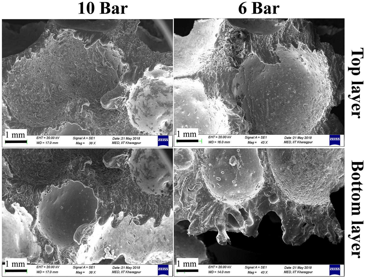
Cross section view of the laser cut zone with argon assist gas.
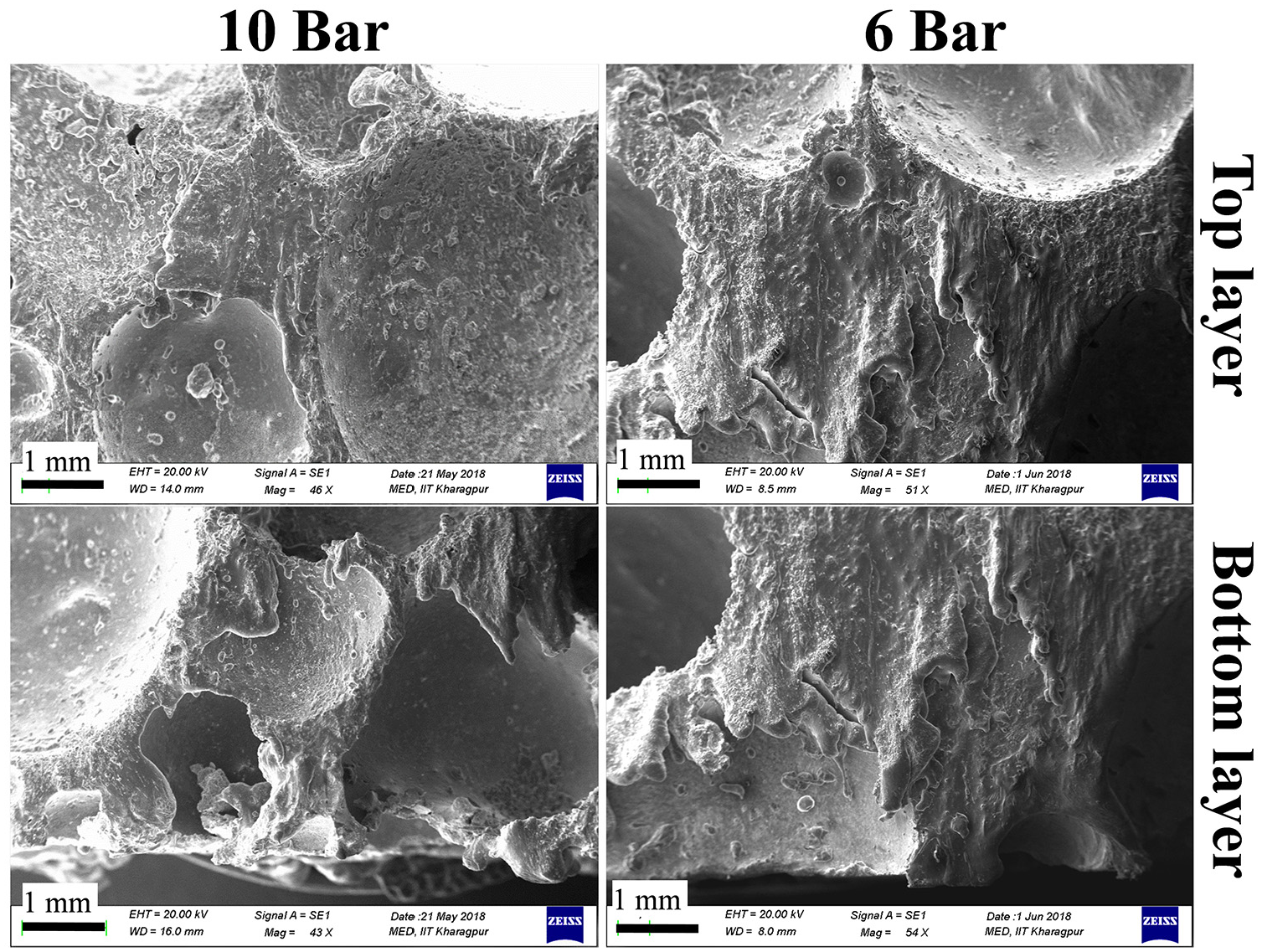
Cross section view of the laser cut zone with nitrogen assist gas.
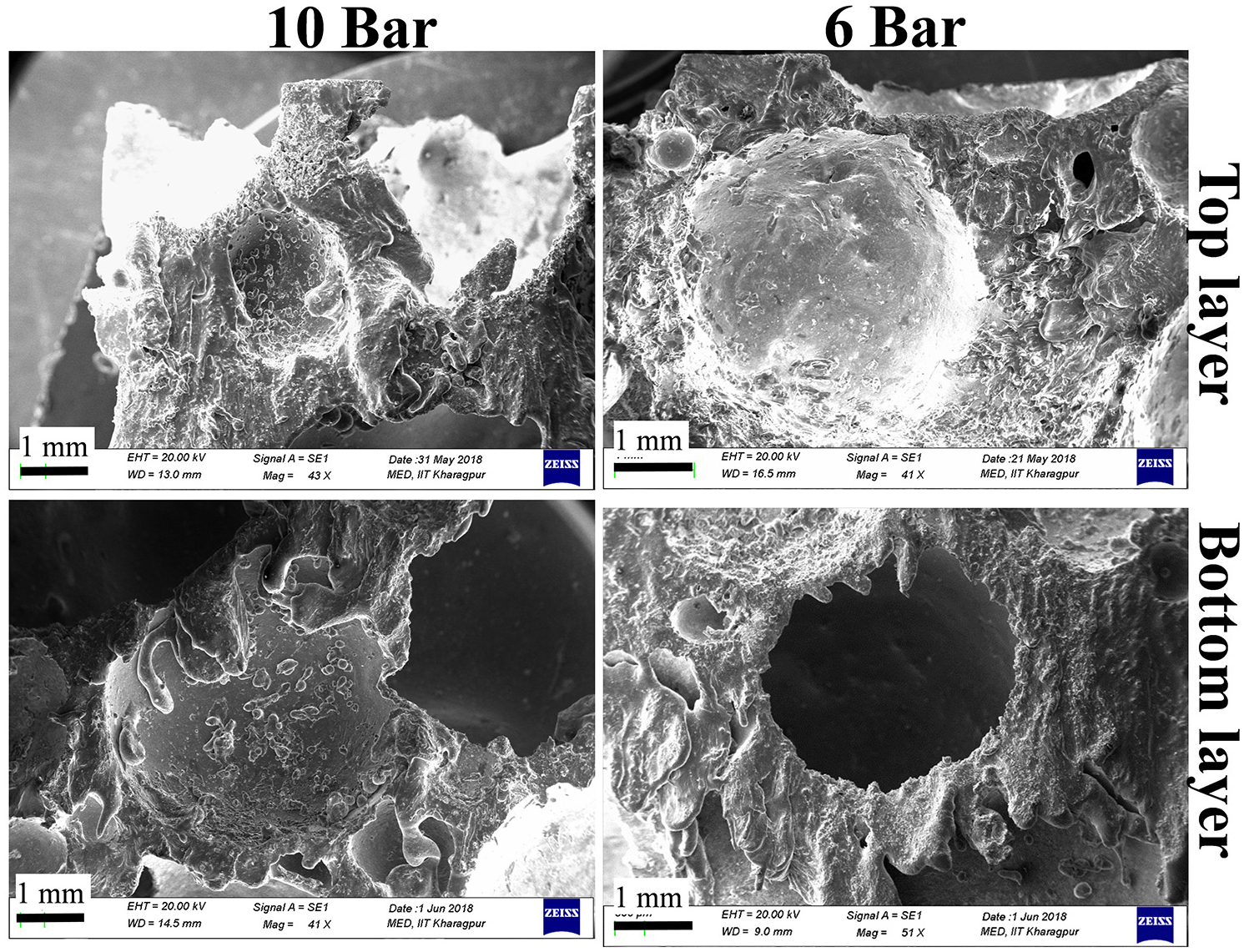
Cross section view of the laser cut zone with oxygen assist gas.
Thermal history of the laser cutting process
Thermal history collected during the experiment showed that it was difficult to get the temperature signal of the cut zone due to its inherent material removal phenomena both in the focussed area as well as in the complex profile of metal foam. However, the trend in the variation was reasonably identified due to the high resolution and quick response time of the pyrometer which transmitted around 1000 signals/s, detecting the temperature of the cut zone before the melt got removed due to the gas pressure. The temperature value obtained showed that the average of the maximum temperature for argon, nitrogen and oxygen was around 545.68 °C ± 15 °C, 617 °C ± 9 °C and 672.11 °C ± 35 °C, respectively. Figure 11 showed some of the temperature signals for different laser processing conditions. The dynamic behaviour of the melt zone resulted in obtaining many peak points in the temperature signal values. The reason for the variable peak points was discussed in section ‘Methods and experimentation’. The maximum temperature value (Figure 12) confirmed the presence of different reactions that occurred in the cut section between the assist gas and the gas trapped in pores. The exothermic reaction occurring in case of nitrogen and oxygen generated the extra heat that got exhibited in the form of the higher maximum temperature signal. Also, the uncontrolled oxidation reaction in the cut zone generated spark and caused the temperature signal to fluctuate to a more considerable extent. Pyrometer readings confirmed that the assist gas with in-situ reactions helped in the laser cutting process of Al foams.
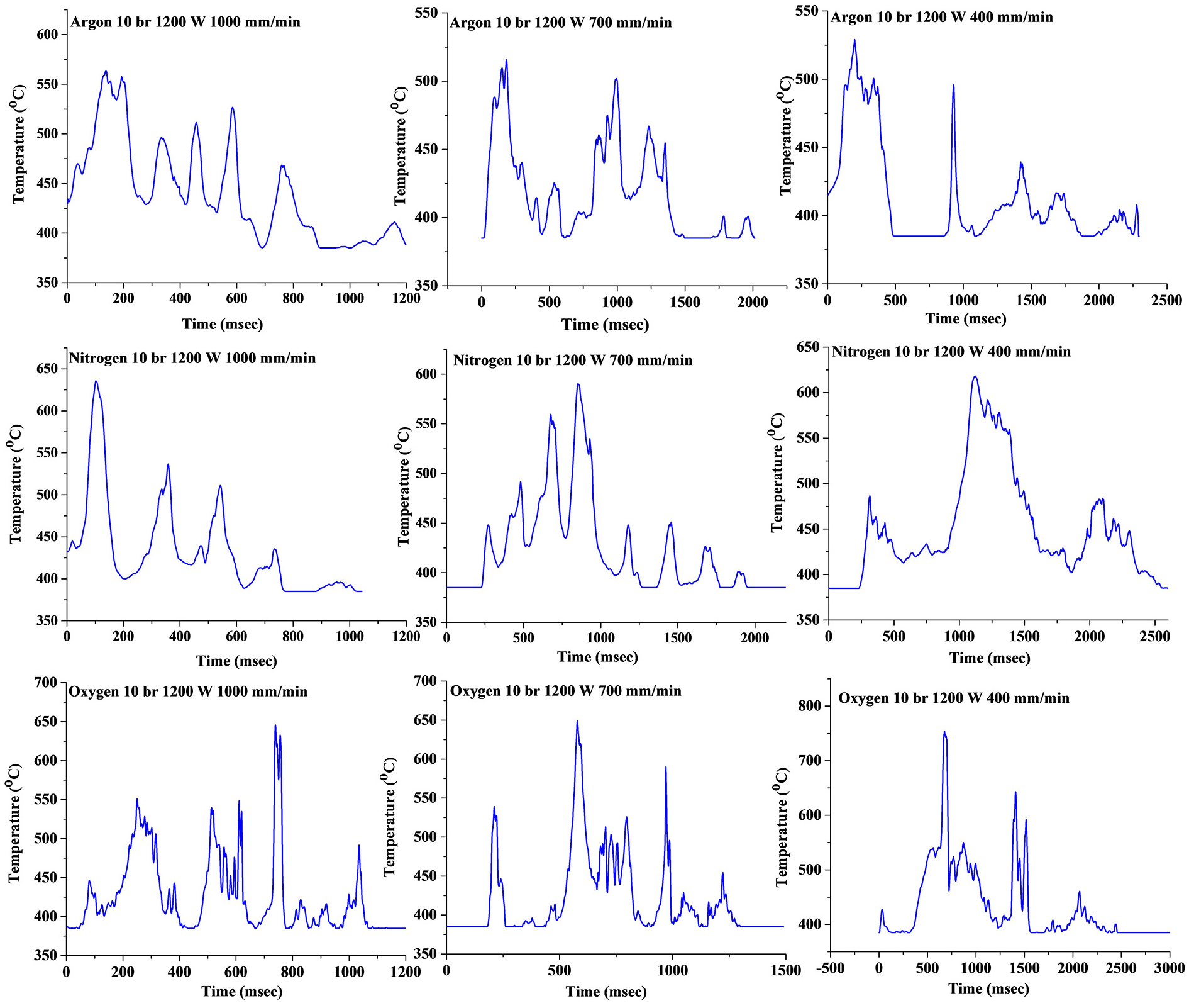
Temperature signals for different laser processing conditions.
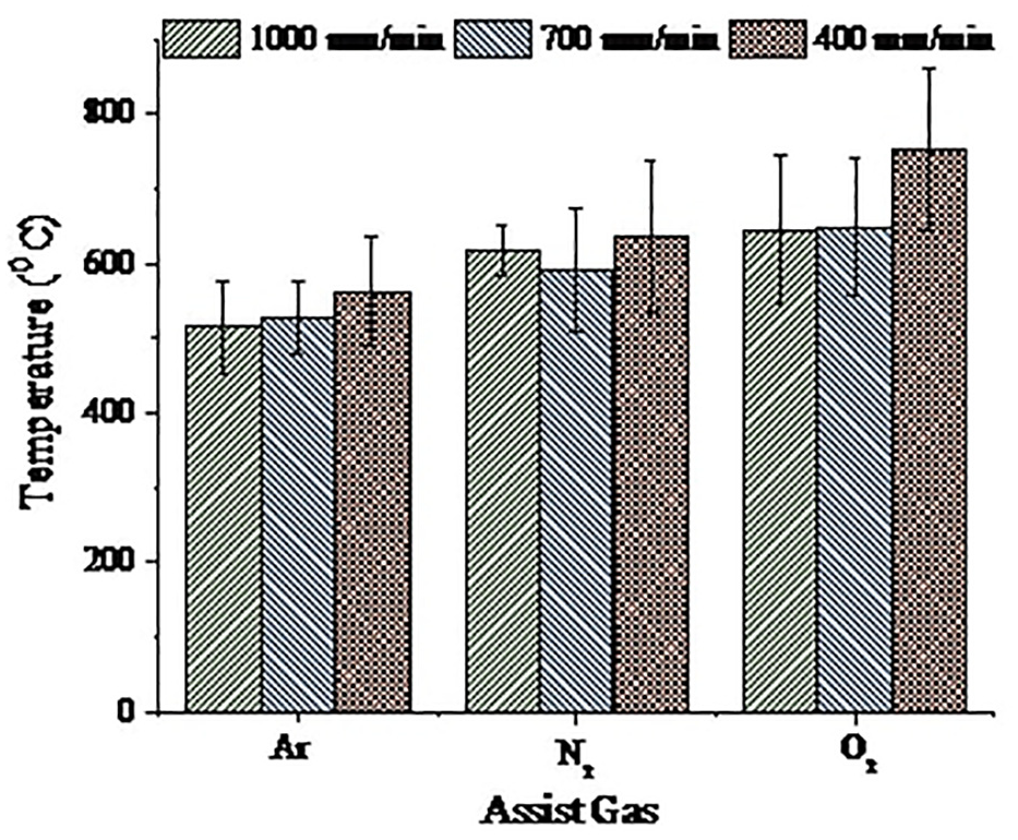
The maximum temperature achieved for different laser processing conditions.
Element and phase analysis
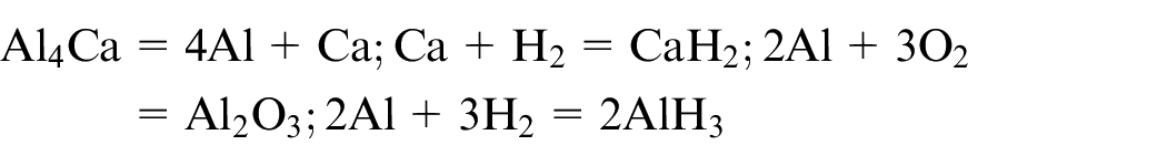
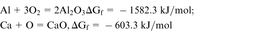
Figure 13 showed the elemental analysis of the laser cut surface with argon, nitrogen and oxygen environment. The result showed that some amount of nitrides and oxides were present in the kerf zone. The higher composition of nitrogen in case of nitrogen assist environment further resulted in the formation of nitride compounds. The oxide content was higher for oxygen assist gas as per Figure 13(c). In the case of argon as an assist gas, the only possible reaction was between Al–Ca alloys with H2 gas. However, in all the cases, some amount of oxide formation was observed, and the expected reaction based on elemental composition analysis and phase analysis is as follows
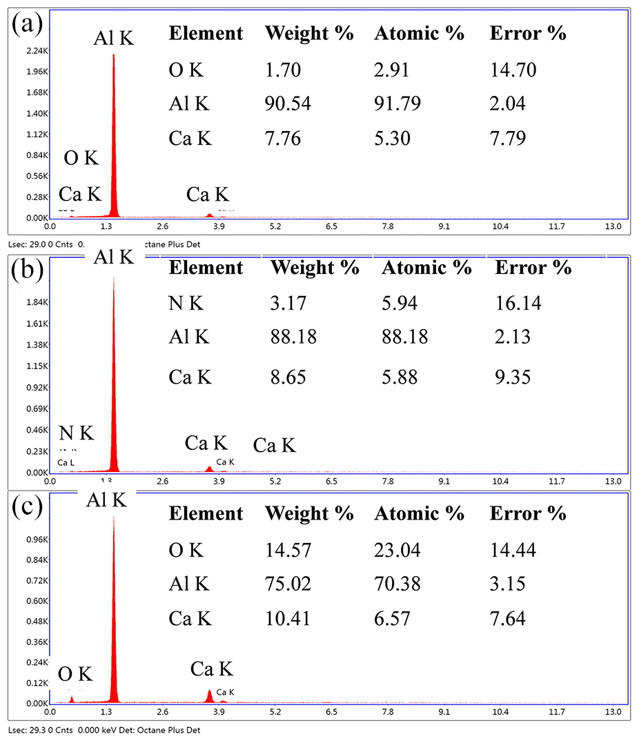
EDS analysis laser cut surface with (a) argon, (b) nitrogen and (c) oxygen environment.
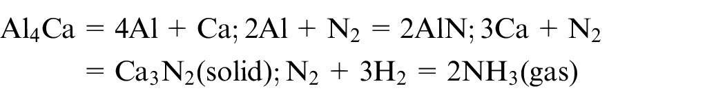
Nitrogen has an affinity for both Al–Ca system and hydrogen. The reaction of N2 with H2 produced NH3 gas where liquid aluminium catalysed the reaction. 36 The final result was a decrease in surface tension due to the generation of NH3 gas. This decrease resulted in a lesser dross attachment and a better surface, as observed in Figure 9. The probable reactions taking place in nitrogen environment are as follows
In the case of oxygen environment, aluminium reacts with oxygen to form oxides. The oxygen also reacts with H2 to form water vapour, decreasing the viscosity of the melt pool. Due to spark generated during the formation of oxides, the reaction generated explosive spatter in the molten material, which resulted in distorted cutting edges, as discussed in section ‘Morphological aspects of the kerf width after the laser cutting process’. The probable reaction in the presence of oxygen is as follows
Based on the findings, it can be inferred that the mechanism of cutting, for the present experimental conditions, in case of argon was melt and shear, for nitrogen it was melt and shear with mild in-situ reactions, while in case of oxygen it was melt and shear with vigorous oxidation reactions.
Figure 14 explains the X-ray diffraction plot of the phases formed in the cut section. Formation of various phases gives an idea of the probable reactions taking place in the cut section. The main compounds observed in phase analysis were Ca3Al2O6, Al2O3, Al4Ca, AlN, Ca3N2, CaO and AlH3.
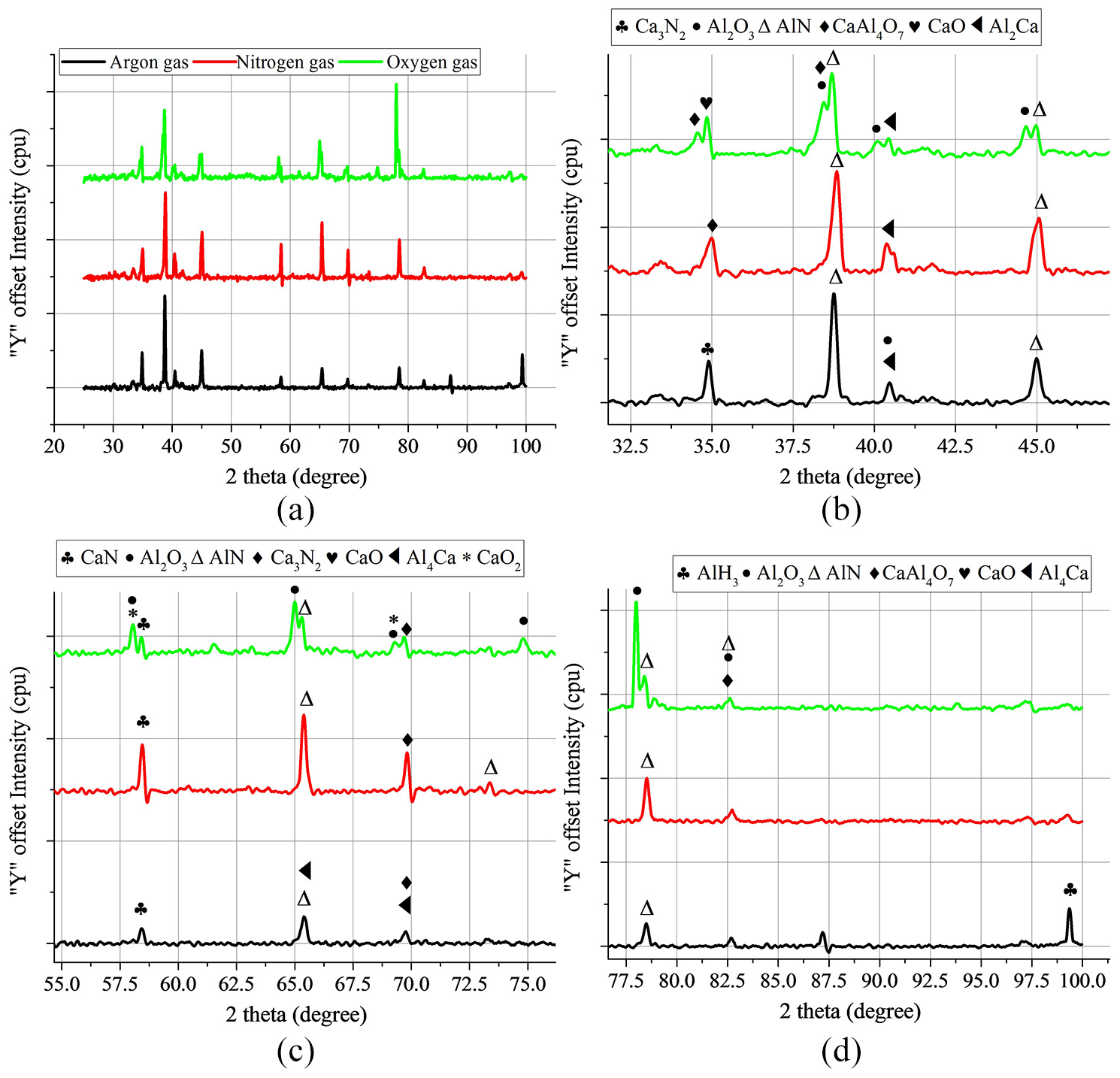
X-ray diffraction pattern of the laser cut section generated with different assist gases showing: (a) overall diffraction pattern and (b, c, d) enlarged diffraction patterns for different two-theta values.
Aluminium nitride peak at around 39° (38.7°) having ICDD 01-087-1054 was present for all the three gas environments. The manufacturing route of the closed-cell aluminium foam used for the experiment might be the reason behind the presence of aluminium nitride peaks in all the three gas environments. Elemental analysis (Table 1) of base material also showed the presence of nitrogen and oxygen in the aluminium foam. Probably during melting and resolidification at the time of manufacturing, the nitrogen might have reacted with aluminium at the exposed surface and have resulted in the phase formation of aluminium nitride, which can be observed during phase analysis as a peak.
Oxygen showed twin peaks or the overlapped peaks at around 40°. These peaks correspond to various oxide phases of aluminium and calcium. The in-situ oxidation reactions occurring in the case of oxygen generated new phases exothermally. These reactions were also confirmed with the pyrometer thermal signatures as well as scattered dross/cross section morphology of the aluminium foam. The nitrogen environment, although showed similar peaks as of argon gas, new phases and precipitates in the cut zone caused the variation of intensity, as well as twin peak formation at around 41°. The full width at half maximum (FWHM) peak at around 65.41° showed that aluminium nitride peak was prominent for nitrogen assist gas than argon assist gas. Similarly, FWHM at 69.7° showed the formation of calcium nitride for nitrogen assist gas. For argon environment, presence of aluminium hydride at the peak position of 99.3° could be explained based on the presence of inert assist gas that resulted in the particular phase reaction. The overall process diagram can be summed up as per Figure 15, which clearly shows the difference in interaction phenomena occurring during the process.
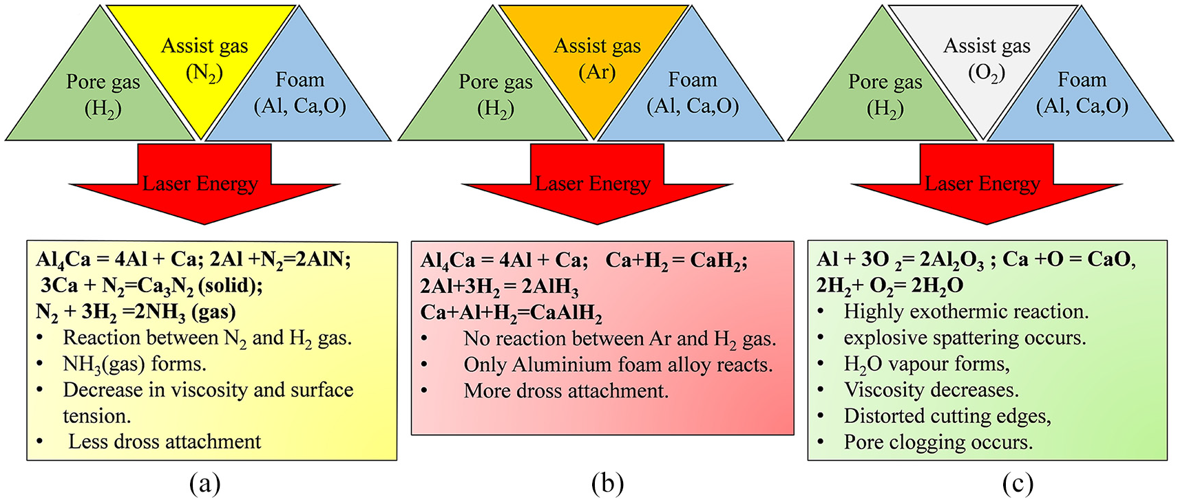
Overall process diagram of the interaction effect of assist gas with gas-filled pore foam during the laser cutting process for: (a) nitrogen, (b) argon, and (c) oxygen assist gas.
Conclusion
Summarizing the present work, laser cutting of closed-cell aluminium foam was performed using argon, nitrogen and oxygen environments and the cut section was analysed morphologically and chemically, along with its thermal analysis. Following conclusions could be drawn from the work:
The laser successfully cuts the Al-foam in all the assist gas environments without distorting the pore shape and size except for oxygen. Argon-assisted laser cutting generated the minimum top kerf width.
Absence of laminar striation marks, as in case of bulk metal cutting, showed the diffusion of the gas pressure due to the presence of the pores. The narrow directionally constricted flow of assist gas, as in bulk metal cutting, was not observed in aluminium foam cutting.
The dross attachment was concentrated around the peripheral edge of the pores. The dross attachment was the highest for oxygen, followed by argon and nitrogen environment, respectively. The pore internal surface showed the presence of spatter in case of oxygen.
Unlike cutting of bulk material where assist gas increases the viscosity of the melt, in case of Al-foam cutting having hydrogen gas trapped in its pores, the generation of gases like NH3 and H2O causes a decrease in viscosity of the melt zone. The result was also in line with the obtained thermal signals of the laser cutting zone, which showed a higher temperature rise in case of nitrogen and oxygen.
The elemental and phase analysis confirmed the in-situ reactions occurring in the cut section as well as the formation of new phases.
Footnotes
Acknowledgements
Authors acknowledge Dr Gopinath Muvvala (ex-Senior Scientific Officer, IIT Kharagpur) for helping in data acquisition through pyrometer during experimentation.
Declaration of conflicting interests
The author(s) declared no potential conflicts of interest with respect to the research, authorship, and/or publication of this article.
Funding
The author(s) disclosed receipt of the following financial support for the research, authorship, and/or publication of this article: Authors gratefully acknowledge the financial support from the Department of Science and Technology, Ministry of Science and Technology, Government of India, under the FIST Program-2007 (SR/FIST/ETII-031/2007).