
Abstract
Owing to the increasing industrial demand for carbon fibre–reinforced polymer composite materials, the interest in effective machining technology grows. The current carbon fibre–reinforced polymer machining technique is dominated by mechanical milling, which often results in high tooling cost and some defects in the machined materials. The exploration of alternative machining techniques is becoming more important. Laser machining as an advanced non-contact technique can potentially improve the machining of carbon fibre–reinforced polymers. However, thermal damages to the machined materials owing to the inhomogeneous, anisotropic and heterogeneous features of these materials have been prohibiting the application of laser machining in industrial scale for carbon fibre–reinforced polymers. In this article, an investigation on the basic characteristics of high-power single-mode ytterbium-doped fibre laser machining of carbon fibre–reinforced polymer is reported. Statistical analysis was performed for the optimisation of the process parameters in single-pass cutting. Furthermore, quality improvement was achieved by the use of multiple-pass cutting technique, which was found to be effective to minimise delamination at low power level and high scanning speeds.
Introduction
Lasers as non-contacting and nonabrasive machining tools exhibit unique advantages in material processing, eliminating tool wear, vibrations and cutting forces and have often been proposed as a promising tool for machining of composites over the past 30 years. The challenges to laser processing are to minimise or eliminate thermal damage and maintain high processing speed. Defects, such as heat-affected zone (HAZ), charring, matrix recession and delamination due to intense thermal effects, are major obstacles for industrial applications of laser machining of carbon fibre–reinforced polymer (CFRP) composites. 1 Quality improvements achieved in laser cutting of CFRPs using techniques such as an additional coolant (water) 2 or cryogenic assist gas,3,4 pulsed and/or ultraviolet (UV) beam processing5–9 show the potential in laser machining of CFRPs.
A summary of the desirability of different machining processes used for CFRPs is given in Table 1. 10 As can be seen, laser machining offers some desirability of characteristics. Compared to the abrasive waterjet process, which is also widely used for cutting of CFRPs, lasers can achieve narrower kerf widths and higher cutting speeds, while offering capabilities of cutting near the edges.11–13 However, as a thermal process and owing to the wide differences of thermal properties of constituents in CFRPs, laser machining can induce thermal damage such as delamination, matrix recession and tapered cut kerf. 14
Desirability characteristics of machining processes for cutting of CFRP composite materials. 10
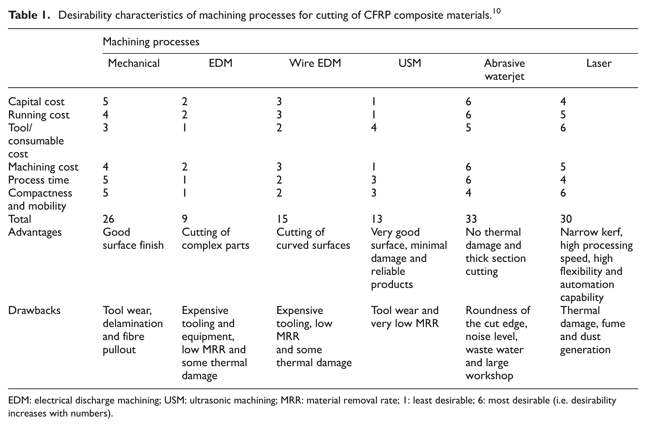
EDM: electrical discharge machining; USM: ultrasonic machining; MRR: material removal rate; 1: least desirable; 6: most desirable (i.e. desirability increases with numbers).
Generally, in fibre-reinforced polymer (FRP) composites, when fibres and matrix exhibit closer thermal properties (e.g. polyester resin and aramid fibre), the composite thermal behaviour can be microscopically homogeneous. Therefore, aramid fibre-reinforced polymer composites (AFRPs) behave better under laser cutting. 15 Up to 9.5-mm-thick AFRP laminates were cut by a laser, 16 and laser machining rates of 2.5 times that of mechanical cutting speeds can be achieved. 12 Glass and carbon fibres, on the other hand, show much more different thermal properties as compared to the resin matrix. Therefore, under many processing conditions, fibres remain unchanged while the matrix reaches its vaporisation temperature. This causes a matrix recession zone. This together with the highest thermal conductivity of carbon fibres (as compared to other types of fibres) leads to vulnerability of laser cut quality of CFRPs.5,17 The major quality defects in laser cutting of CFRPs are given in Figure 1. While matrix recession and tapered cut kerf can be potentially minimised5,8 and even repaired, 18 the delamination remains the most challenging defect in laser cutting of CFRPs.
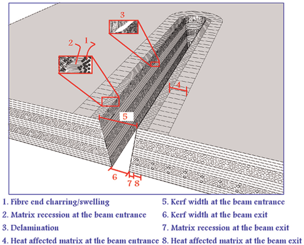
Quality characteristics in laser cutting of CFRPs.
Recent developments in laser materials processing technology have opened new opportunities. These include availability of high power, high beam quality and short and ultrashort pulsed systems as well as modern high-precision linear motor Computer Numerical Control (CNC) stages and galvanometer scanner that allow rapid laser–material interaction to improve process productivity, quality and accuracy. The visible light and near infrared wavelength laser beams (e.g. fibre laser) can also be transmitted through fibre optics and manipulated by industrial robots (to distances over 200 m from the laser unit). These factors have led to availability of systems with practically negligible energy coupling loss, high beam quality, compact and reliable diode pumped solid-state (DPSS) laser systems with minimal maintenance requirements. Currently, the disc and the fibre lasers are two competing technologies to change the operational performance of industrial lasers dominated by CO2 and Nd:YAG lasers. 19 Fibre lasers in particular are being successfully used in novel ways for high-speed and high-quality cutting and welding industrial applications.20,21 In the present study, an experimental investigation on the characteristics of high-power single-mode laser cutting of CFRPs is presented with a particular focus on delamination.
Experimental procedure
An IPG YLR-1000-SM single-mode 1 kW fibre laser system was used in this study. The focusing position can be axially adjusted in the range of −20 to +10 mm. The concept of focal plane position (FPP) with regard to the surface of the workpiece is given in Figure 2. A 1-mm-exit diameter converging nozzle was used, and the stand-off distance of the nozzle was kept constant at 1 mm. The samples used in the analysis were fully cured, Toray® T300 carbon fibre–reinforced Nelcote® E-710 Epoxy resin. The stacking sequence of the lamina was 0/45/90/-4518. The composite plate was covered with a thin layer of woven carbon fibre fabric with a weft-to-wrap ratio of 1, at both sides. The thickness of the material was 2 mm and fibre volume fraction was 70%.
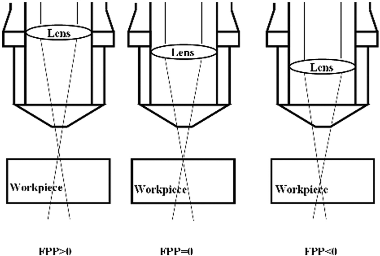
Concept of focal plane position with regard to the surface of the workpiece.
The samples were prepared with the same dimensions (100 × 100 mm) and mounted on a high-speed single-axis linear motor stage (Figure 3). For acceleration purposes, a start up distance of 15 mm was considered from the edge of samples, and the cut length was kept as 40 mm throughout the analysis. Since the investigation of thermal damage is a focus of this study, a cross-cutting strategy (where laser scanning direction is perpendicular to the fibre orientation in the top layer) was used to obtain a better understanding of quality improvement. This is because high thermal conduction of carbon fibres induces the most matrix recession damage in this case, while when the scanning direction is parallel to the fibre orientation, this damage is much less.5,10,22 The cut samples were then analysed using optical microscopy and scanning electron microscopy (SEM).
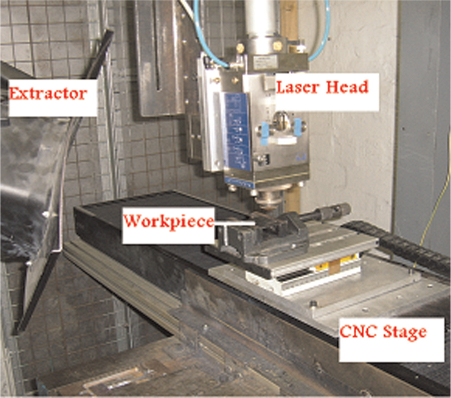
Experimental set-up in fibre laser cutting experiments.
Controlling the heat input helps the reduction of thermal damages in laser cutting of CFRPs. 13 This could be achieved by different mechanisms such as short and ultrashort pulsed beam processing (to increase heating/cooling rate and reduce thermal interaction time), higher cutting speeds, multiple-pass cutting (to reduce interaction time and beam intensity in unit length) and additional coolant medium (to increase heat dissipation from the material).
Commonly in laser cutting of materials, the quality is assessed in response to variation of one process parameter at a time. This requires a large number of experimental runs and hence can be lengthy, expensive with respects to both the process and the material requirements. Investigating the interaction effect among multiple parameters is also very difficult in this approach. In laser material processing, interactions may involve a number of process parameters such as laser power, processing speed, FPP, beam spot size and so on. Statistical analysis as a scientific approach has been diversely accepted in experimental research studies to minimise the experimental runs, on one hand, and optimise the quality criteria with the consideration of multiple parameter interactions during the process, on the other hand.6,23,24
Therefore, a response surface method (RSM) was used to identify the significant processing factors and quantify the relationships with the measured outputs in single-pass cutting. Since the response may be influenced by multiple design factors, the central composite design (CCD), which was found to be the most efficient in terms of the number of runs required, was used. Thereby, an analysis of variance (ANOVA) was performed on the experimental outcomes (i.e. responses), and the optimum process parameters window for single-pass cutting was confirmed. A summary of the design of experiment (DoE) procedure is given in Figure 4. Then, based on these findings, the effect of energy per unit length and millisecond modulated pulsed beam processing of the material were investigated more in depth.
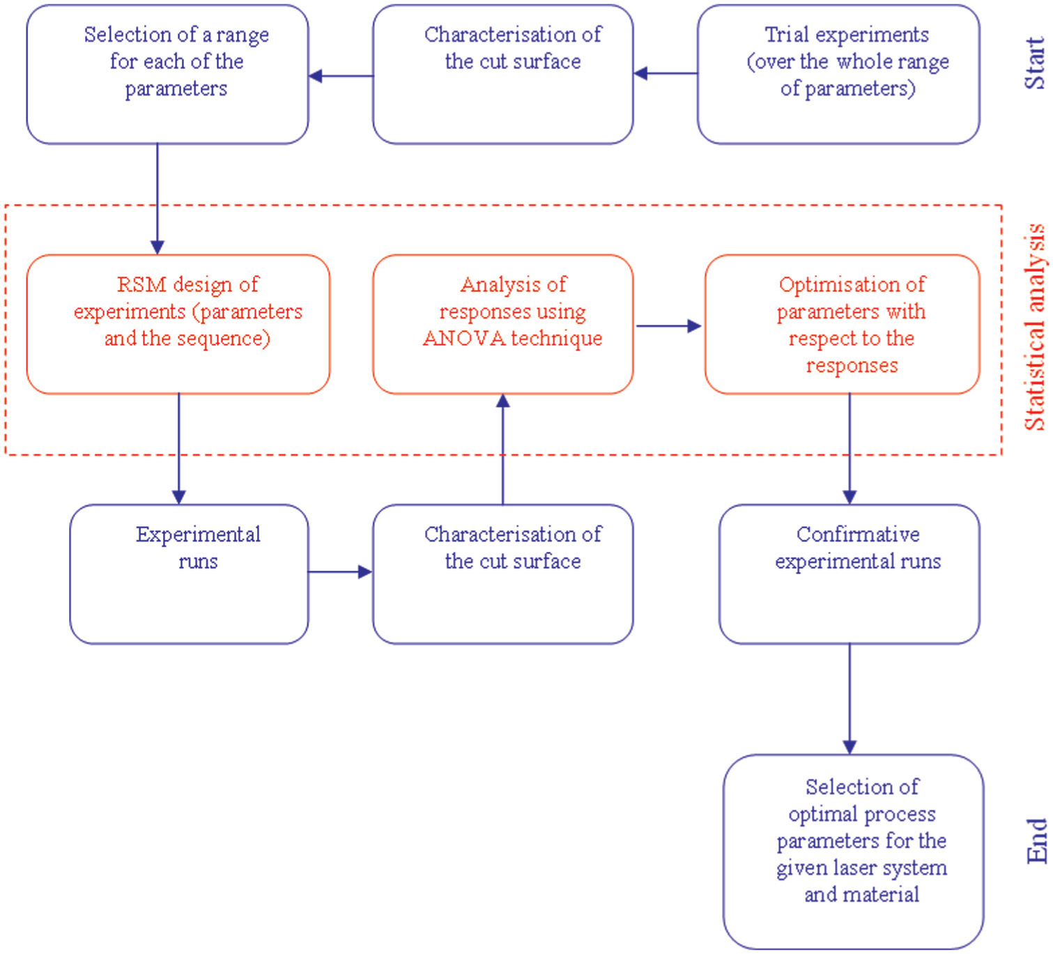
Sequential procedure of design of experimental investigations.
Results and discussion
Generally, laser power density and interaction time show major effects on the extent of thermal damages in laser processing. 25 Laser power (controlling the power density) and cutting speed (controlling the interaction time) are the dominant factors influencing the quality in laser cutting of FRPs.15,17 In laser cutting, the main process conditions can be incorporated into a single parameter (energy density, Ed) as4,12,22,26
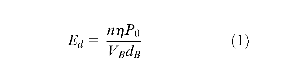
where n is the number of beam passes, η is absorptivity, P0 (W) is the beam power, VB (mm/s) is scanning speed and dB (mm) is the beam spot diameter. For the same material and beam diameter, this can be summarised as the ratio of power to scanning speed (energy per unit length) multiplied by the number of passes. Thus, a reduction in energy per unit length can be achieved by decreasing power and/or increasing the scanning speed, which would consequently increase the number of passes required for a through cut. A through cut is referred to the cutting cases where the incident laser beam passes through the whole thickness of the sample and exits from the bottom side of the sample. As the speed governs the power input per unit length, a minimum critical energy input exists at which a through cut can be achieved with minimal thermal damage. This maximum speed limit above which no through cut occurs depends on the material thickness and power density. 27
Single-pass processing is the dominant approach in laser cutting applications owing to the maximised material removal rate (i.e. minimised operational time). Figure 5 shows the power and corresponding scanning speed levels that led to through cuts. As depicted, the results revealed a proportional relationship between the beam power and the scanning speed for a through cut. It was also observed that the material could not be cut through using a power level below 230 W even at low scanning speeds (e.g. 1 mm/s). This is due to insufficient energy density ratio to penetrate the full thickness of the material.

Relationship between power and scanning speed for through cuts using fibre laser in assistance of 5 bar N2.
Since large thermal damage was observed as inevitable, the use of statistical DoE was found expedient to provide maximum information from a reduced number of experimental tests. Hence, statistical DoE was used to optimise the processing parameters for the single-pass cutting. These optimum parameters were then applied for further analyses including the effect of assist gas, FPP and energy deposited per unit length of cut path on cut quality.
DoE
A third-level CCD response surface analysis with two repeats was conducted in order to obtain the optimum process conditions. Five repeats of experiments were conducted for the centre point in order to achieve high accuracy of the statistical analysis. Design Expert® software was used to design the experiment with four parametric factors (i.e. laser beam power, scanning speed, gas pressure and FPP). The scanning speed ranges were confirmed following initial trial runs to realise the through cut condition at maximum and minimum power levels of the system in a single pass. The FPP range was considered from −4 to +4 mm as the trial experiments confirmed this range to provide minimum spot size.
The factors and their ranges considered in the experimental design are presented in Table 2. It was suggested that in continuous wave (CW) beam laser cutting of CFRPs, maximum power at the maximum scanning speed should be used.17,27 Therefore, the range of power was considered over the whole efficient range of the system. Scanning speed range was confirmed from the establishing phase (Figure 5). The assist gas throughout this process optimisation experiments was nitrogen.
Range of parameters in CCD analysis of single-pass fibre laser cutting.
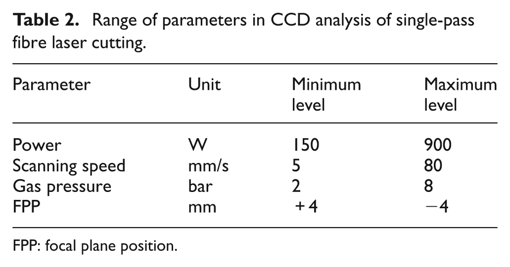
FPP: focal plane position.
Analysis of responses
After designing and running the experiments, the responses were measured and recorded. An ANOVA was then performed, and optimised process parameters were obtained. This approach narrows down the process parameters window. This window was then used for further analyses of the process. Since not all combinations of process parameters led to through cuts (due to the insufficient energy per unit length levels), only the matrix recession and kerf width at the beam entrance and the cut depth were considered as the responses in this section of the study.
Figure 6 illustrates the influence of the significant factors that were determined by ANOVA technique for matrix recession and kerf width at the beam entrance and cut depth in single-pass cutting. Matrix recession and kerf width were most significantly influenced by the combination of power and FPP. The relationship between these process factors is clearly shown as a contour graph in Figure 6(a) and a three-dimensional (3D) graph in Figure 6(b) for matrix recession and kerf width, respectively.
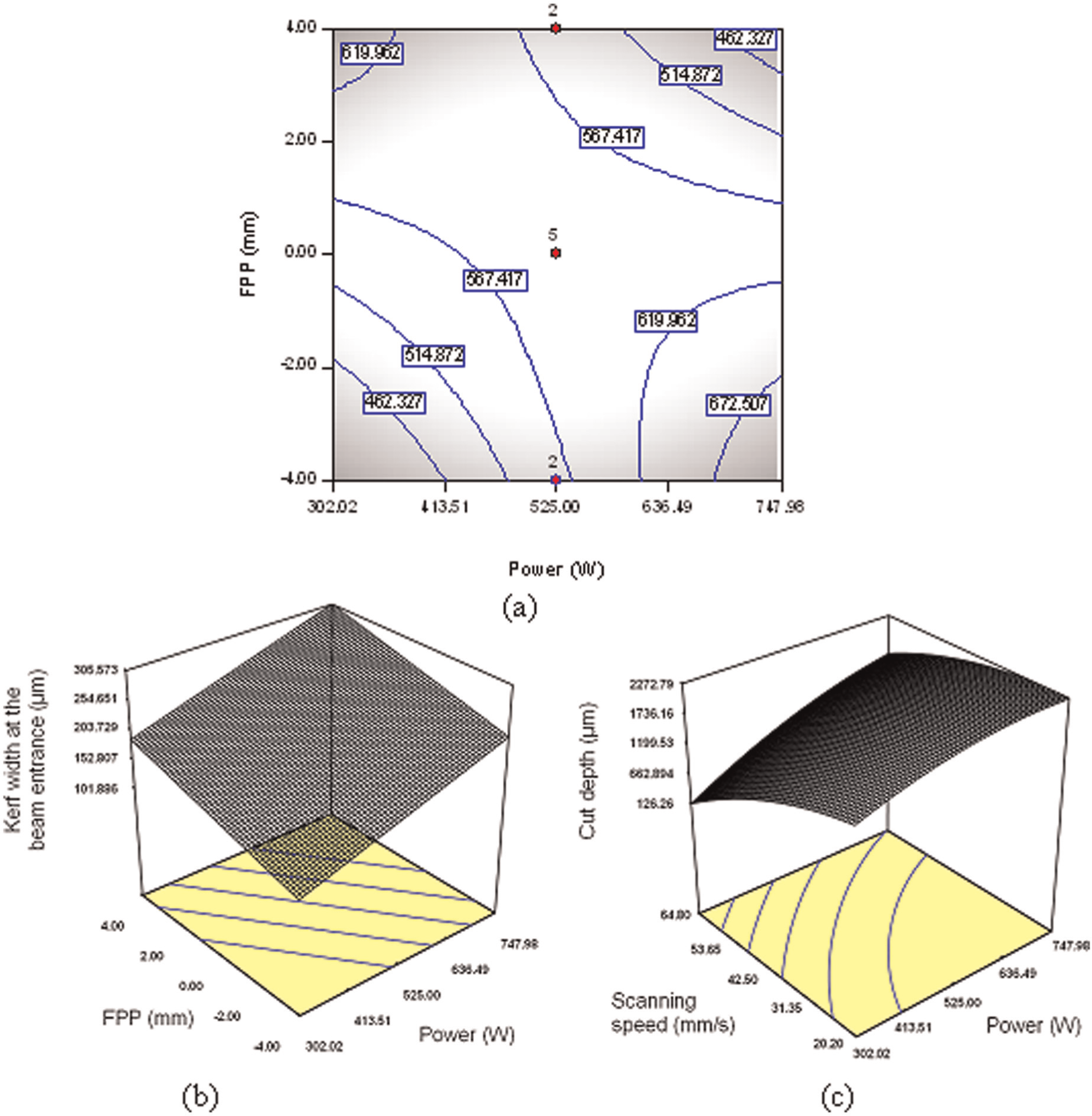
Effect of significant factors on (a) matrix recession, (b) kerf width at the beam entrance and (c) cut depth in single-pass fibre laser cutting with 5 bar nitrogen assist gas.
Generally, as can be observed from Figure 6(a) and (b), the combination of low power and focusing the beam below the top surface of the workpiece reduces the matrix recession and kerf width. Although the combination of high power and focusing the beam above the top surface of the workpiece also showed a reduction of matrix recession (Figure 6(a)), this combination was not desirable as it increased the kerf width (Figure 6(b)). Laser beam power and the scanning speed were the two significant factors influencing the cut depth, as shown in Figure 6(c). Increasing power, on one hand, and decreasing the scanning speed, on the other hand, increased the cut depth through more heat input.
Optimisation
Performance assessment of laser cutting of CFRPs consists of three criteria, which are the thermal damage and the geometry defects and process time. 5 The process is optimised once maximum cut depth is achieved with minimal amount of energy input (thermal damage). Statistical optimisation of responses can be achieved through an objective function known as desirability, which considers the effect of each parameter as well as its interactions with other parameters over the entire range of responses. Full explanation of the desirability function and optimisation process are available in the literature. 28 The optimum (i.e. minimised HAZ and cut kerf and maximised cut depth) predicted solutions for single-pass cutting in this study are presented in Table 3. The lower ranges of power and the scanning speed with FPP below the material were predicted to provide optimum quality and performance for the system. Based on the first solution, which gave maximum desirability, a power level of 340 W and a scanning speed of 20 mm/s were adopted for detailed analysis of the process.
Optimum solutions predicted for the fibre laser cutting of 2-mm-thick carbon fibre/epoxy laminates.
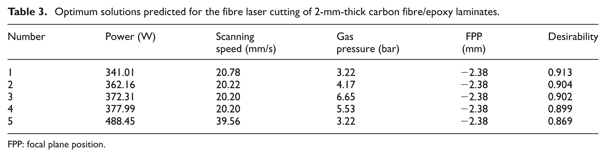
FPP: focal plane position.
Effect of assist gas
Assist gas type and pressure are an important factor in laser cutting to protect the optics, remove by-products and dissipate heat from the cut zone. The effect of the assist gas type and pressure is studied in this section. Nitrogen, oxygen and argon were used at different pressures to investigate the effect of characteristics and pressure of the assist gas on the process.
Figure 7 illustrates the influence of the assist gas type and pressure on the quality at 340 W laser beam power, 20 mm/s scanning speed and −2.38 mm FPP (as in optimisation results from DoE). Generally, as can be observed, for the inert gases (i.e. nitrogen and argon), increasing the assist gas pressure decreased the matrix recession and the kerf width both at the entrance and at the exit sides. In the case of oxygen, however, although the matrix recession was reduced by increasing the gas pressure, the kerf widths both at the entrance and at the exit showed an increase with the increase in the assist gas pressure. This was caused by accelerated decomposition/vaporisation of material through oxidation.29,30
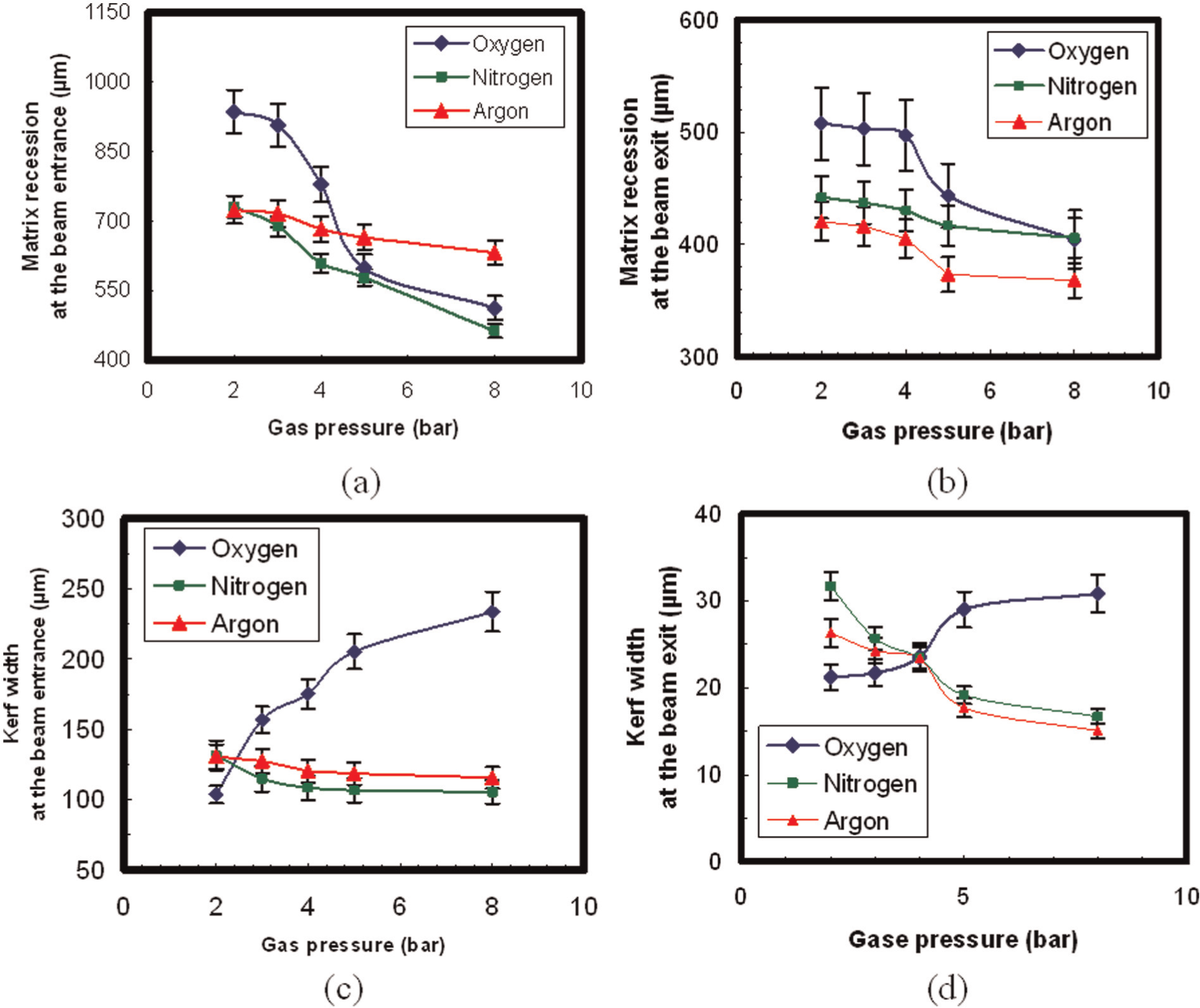
Influence of assist gas type and pressure on the matrix recession at (a) beam entrance and (b) beam exit and the kerf width at (c) beam entrance and (d) beam exit (340 W laser power, 20 mm/s scanning speed and −2.38 mm FPP).
Effect of FPP
A distinctive advantage of single-mode fibre lasers is their low beam divergence as a result of their high beam quality (i.e. beam parameter product <1). This has extended the working distance (focal depth) considerably as compared to other laser systems used in industry. 19 In the case of composite materials, the research on the effect of laser FPP in the machining processes is not yet known. Therefore, the influence of FPP on fibre laser cutting of CFRPs is reported in this article. The power density at the workpiece surface varies with changing FPP, with the change in induced beam spot size at the surface. This influences the thermal damage on the material. Figure 8 illustrates matrix recession and kerf width at the beam entrance side for different FPPs (i.e. range of −2.38 to 2.38 mm) at the constant process parameters of 340 W power, 20 mm/s scanning speed and 8 bar assist gas pressure.
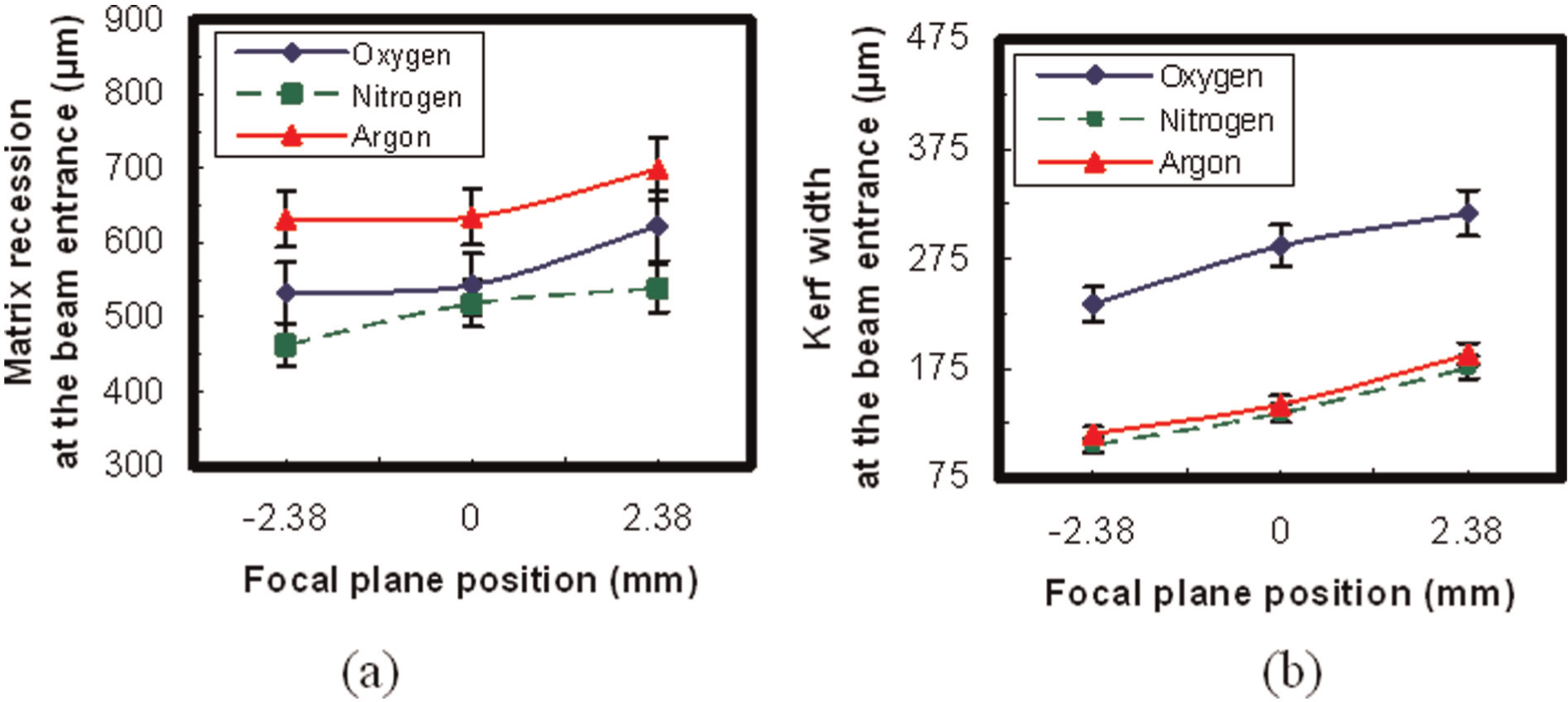
Influence of focal plane position and assist gas type on (a) matrix recession and (b) kerf width at the beam entrance at 8 bar assist gas pressure.
Generally, as the FPP was moved upward from FPP = −2.38 mm, the heat damage at the beam entrance increased, which, however, reduced the thermal damage towards the end of the cut depth. This effect caused non-through cuts at 2.38 mm FPP. For the focal plane positioned on the top surface (FPP = 0), the process did not lead to through cuts in the presence of argon. Figure 9 illustrates the microphotograph comparison between the thermal damage at the beam exit side in the presence of oxygen and nitrogen with the focal plane positioned on the top surface (i.e. FPP = 0) at different gas pressures. Increasing the assist gas pressure generally reduces the thermal damage. In the presence of oxygen, the damage is higher. This can be attributed to the exothermal reactions causing combustion of the material. At 8 bar pressure, high thermal dissipation prevented the through cuts for both oxygen-assisted and nitrogen-assisted processes. However, as can be judged from Figure 9, less discontinuity of cut was observed in the presence of oxygen as compared to nitrogen. This is due to the accelerated vaporisation of the fibres through oxidation.
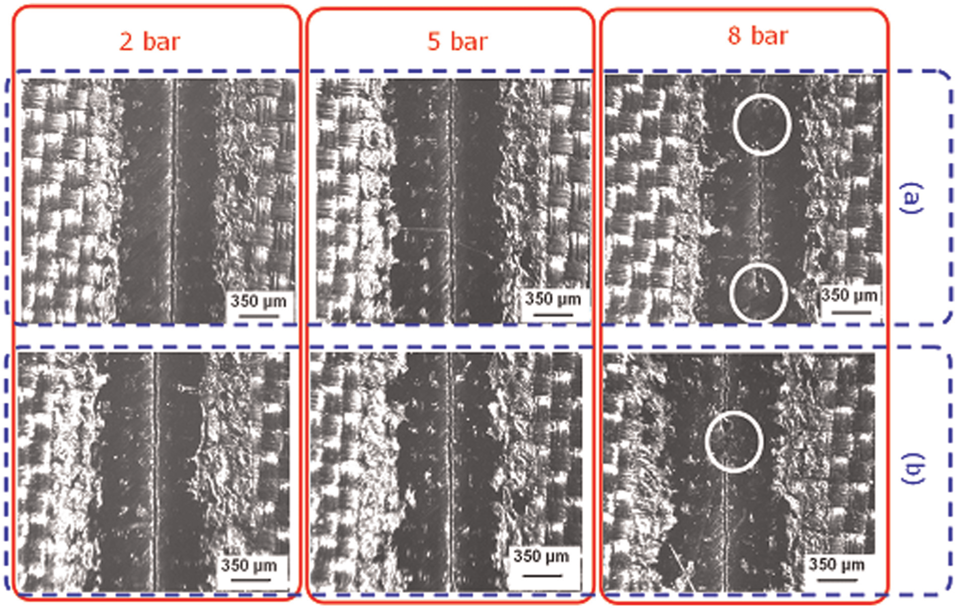
Comparison of thermal damage at the beam exit at different assist gas pressures in the presence of (a) nitrogen and (b) oxygen with FPP = 0.
Effect of energy per unit length
As explained for the same material and beam spot diameter, the energy density factor (equation (1)) can be summarised as
where
Figure 10 illustrates the effect of variation of power and scanning speed at a constant energy per unit length ratio of 17 J/mm. As can be seen in the case of 170 W and 10 mm/s, although the power is less than the optimum condition (i.e. 340 W and 20 mm/s), the reduced scanning speed showed an evident effect in increasing both kerf width and matrix recession. At 680 W and 40 mm/s, the increased power showed a clear effect in increasing kerf width and matrix recession despite the decreased interaction time (as compared to optimum condition). However, the matrix recession (at 680 W and 40 mm/s) is less than the 170 W and 10 mm/s case. Moreover, except for the 340 W and 20 mm/s case, the other cases (despite depositing similar energy per unit length) did not cut through the material. This emphasises the influence of anisotropic characteristics of the material. Different thermal expansion coefficients at different layers enforce a non-uniform heat propagation mechanism along the kerf depth despite the constant energy per unit length ratio. The dominant factor influencing non-through cut at 640 W (i.e. twice the power level in optimum condition) is reduced interaction time. Hence, scanning speed proved to be the crucial factor in laser cutting of CFRPs. This emphasises the influence of interaction time in heat conduction along the high thermal diffusivity carbon fibres.
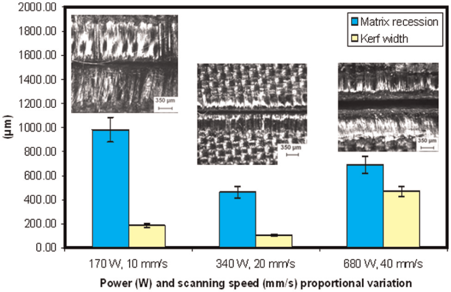
Effect of variation of power and scanning speed at constant energy per unit length ratio of 17 J/mm on matrix recession and kerf width at the beam entrance (at −2.38 mm FPP and 8 bar nitrogen).
As mentioned, increasing the number of passes can also influence the energy density factor. Hence, a multiple-pass cutting approach was used for further investigation at the 340 W power and −2.38 mm FPP (from optimum process conditions). Figure 11 shows the number of required passes for through cuts at the different scanning speed levels, while keeping energy per unit length ratio constant at 17 J/mm. As depicted, a simple statistical analysis showed that the variation of the required number of passes is exponential with respect to the scanning speed. This is again due to the complexities of the heat propagation in the anisotropic and inhomogeneous structure of the material. Nevertheless, analysis of cut surface showed decreased delamination in multiple-pass cutting.
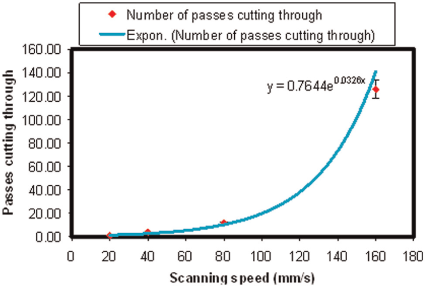
Effect of scanning speed on the number of passes required in experiments for through cuts and the exponential predicted trend (340 W power, −2.38 mm FPP and 8 bar nitrogen).
Figure 12 illustrates the reduction in delamination as scanning speed is increased. This is an interesting finding that can be associated with the high beam quality of fibre laser and particular processing parameters (e.g. FPP below the surface) applied in this study. A previous quality improvement study on laser cutting of CFRPs proved the reduction of delamination to be challenging when using a nanosecond pulsed DPSS Nd:YAG laser, although the matrix recession was reduced considerably. 5 The anisotropic thermal expansion coefficient of CFRPs, which varies in different layers, according to the fibre orientation in each layer, 5 causes variations in delamination. This seems to be unavoidable in CW laser cutting due to high thermal input into the material. However, the proposed technique of multiple-pass cutting using the single-mode fibre laser with the beam spot focused below the material at low power levels and high scanning speeds, proved to provide a desirable combination of processing conditions that can actually minimise delamination formation.
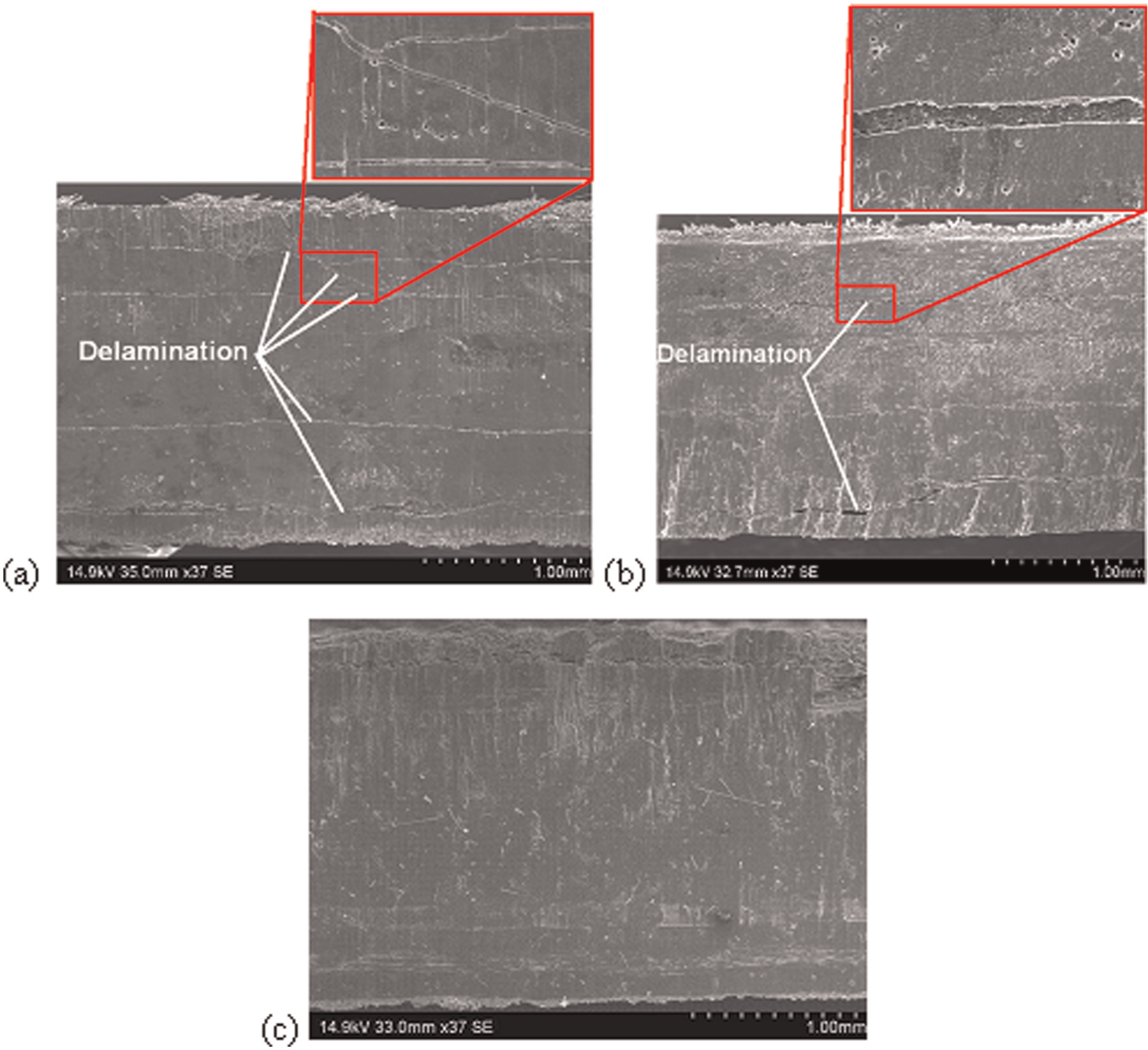
Influence of increasing speed in multiple-pass cutting on delamination at (a) 20 mm/s (1 pass), (b) 40 mm/s (2 passes) and (c) 80 mm/s (12 passes) using 340 W power, −2.38 mm FPP and 8 bar N2.
Conclusion
Beam power and scanning speed were found as the most influential factors in single-pass cutting of CFRP. Thermal damages were found to be generally large in laser cutting of CFRPs. DoE optimised the process conditions successfully. DoE analysis showed that medium power levels (e.g. 340 W) at medium levels of scanning speed (e.g. 20 mm/s) when FPP is below the surface are optimum in single-pass through cutting of CFRPs. The correlation of assist gas flow and other process parameters (e.g. output power and scanning speed) was also found effective in laser cutting of CFRPs. It was found that the cutting quality can be improved using high-pressure inert assist gas. Oxygen as the assist gas increased thermal damage to the material through oxidation. For the current fibre laser system, focusing the beam below the material (i.e. −2.38 mm) was found effective in reducing thermal damages.
Controlling the heat input was found crucial to reduce thermal damages in laser cutting of CFRPs. Therefore, alternative mechanism of multiple-pass cutting was used. The energy per unit length analysis revealed that for the same ratio, variation of interaction time (i.e. scanning speed) influences thermal damage and depth of cut considerably. This was also further confirmed in multiple-pass processing at constant power level and proportional increase of scanning speed and number of passes. Multiple-pass cutting using CW beam fibre laser showed a notable reduction of delamination as scanning speed increased. This is an interesting finding that can be considered for future investigations of laser cutting of CFRPs.
Footnotes
Declaration of conflicting interests
The authors declare that there is no conflict of interest.
Funding
This research received no specific grant from any funding agency in the public, commercial or not-for-profit sectors.