
Abstract
As a key factor, the accuracy of the instantaneous undeformed thickness model determines the force-predicting precision and further affects workpiece machining precision in the micro-milling process. The runout with five parameters affects the machining process more significantly compared with macro-milling. Furthermore, modern industry uses cutters with non-uniform pitch and helix angles more and more common for their excellent properties. In this article, an instantaneous undeformed thickness model is presented regarding cutter runout, variable pitch, and helix angles in the micro-milling process. The cutter edge with the cutter runout effect is modeled. Then, the intersecting ellipse between the plane vertical to the spindle axis and the cutter surface which is a cylinder can be gained. Based on this, the points, which are used to remove the material, on the ellipse as well as cutter edges are calculated. The true trochoid trajectory for each cutting point along the tool path is built. Finally, the instantaneous undeformed thickness values are computed using a numerical algorithm. In addition, this article analyzes runout parameters’ effects on the instantaneous undeformed thickness values. After that, helix and pitch angles’ effects on the instantaneous undeformed thickness are studied. Ultimately, the last section verifies the correctness and validity of the instantaneous undeformed thickness model based on the experiment conducted in the literature.
Keywords
Introduction
With the increase in demand for the miniature workpieces in modern industries such as aerospace, mold and medical equipment, and so on, the micro-milling technology becomes more and more important. 1 The milling size between 1 μm and 1 mm as well as the radius of the cutter less than 0.5 mm define this kind of machining process. 2 Therefore, the studies including cutting forces prediction,3,4 tool deflection, 5 stability prediction,6–8 and surface finishing, 9 and so on about the micro-milling process have become topics of interest.
The milling forces become one key aspect of the technologies to understand the micro-milling process. 10 This is very useful for improving surface quality and productivity. In addition, the accuracy of the force prediction is particularly critical to control and optimize the process. In the most conventional milling force model, the instantaneous uncut chip thickness (IUCT) is one of the most important factors. 11 For the macro-milling process, the IUCT computation often uses the simplified form of the edge’s trace. 12 However, when the machining dimension is less than 1 mm, these simplifications are not suitable for the IUCT’s calculation. The reason for this is that the error in the macro-milling process is small, but large for micro-machining. In order to solve these difficulties, many researchers have studied these issues. Li et al. 13 develop a vibration-assisted micro-milling device and study effect of vibration parameters on surface quality. Kim et al. 14 use a static IUCT model combining the minimum chip thickness. Using the classical IUCT model in macro-milling, G Bissacco et al. 15 presented an IUCT model combining with the cutter runout effect in the micro-milling process. Also, a new nominal uncut chip thickness algorithm for micro-scale end-milling is proposed by considering the combination of an exact trochoidal trajectory of the tool tip and runout, and then the actual uncut chip thickness may be obtained from a comparison of the current accumulative uncut chip thickness and the minimum chip thickness. 16 Newby et al. 17 presented a chip thickness model for micro-milling by considering a trochoidal tool flute trajectory. Bao and Tansel 18 calculated the IUCT values considering the trochoidal trajectory of the edges. Afazov et al. 19 studied the runout parameters’ effect on the IUCT values. They concluded that the runout parameters have great effects on instantaneous undeformed chip thickness. Bao and Tansel 20 also combined the runout effect into the IUCT values. In order to consider more factors influencing the IUCT values, Rodríguez and Labarga 21 introduced the idea that the IUCT’s computation should take the runout, tool deflections, and size effect into account. They presented a new IUCT model combining these factors, and the results show good agreement with experimental data. Li et al. 22 also noticed the effect of the runout effect. They considered the true edge’s trace when computing the IUCT values. In addition, the authors detected the runout parameters using a genetic algorithm. The precision is very high using their model. However, although the true traces of the edges are considered in this model, they simplified the model for using an analytical method to compute IUCT values. Regarding runout determination technologies, Wan et al. 23 introduced an analytical method to compute the runout parameters in the macro-machining. In the micro-milling process, Afazov et al. 19 used a dial indicator to measure the runout parameters. Researchers have made much effort to understand the IUCT forming mechanism in the micro-milling process. Y Chen et al. 24 presented a cutting force model using the mechanical theory regarding one-parameter cutter runout. These studies have made great advances to push forward the micro-machining technologies.
However, two parameters define the runout in above literature. The reason for this is that the cutter axis and the spindle axis are parallel to each other. In reality, these two axes are skew lines. Therefore, two parameters cannot express this situation. Zhang et al. 25 attempted to define this runout by four parameters. The IUCT’s calculation in this article uses a numerical method. 26 Actually, the most common situation of the runout effect must be defined by five parameters. Our previous paper 27 has emphasized this situation. This finding comes from an ideology in the literature 28 and is used to study the cutting forces. 29 However, in the micro-milling process, there have been few studies about the runout effect defined by five parameters on the IUCT values and cutting forces. In addition, no literature researches the IUCT model for the cutters with the non-uniform helix and pitch angles.
Cutting forces significantly influence workpiece accuracy, fixture design, tool path optimization, and so on. Since the precision of IUCT model is vital for cutting forces, this article presents a novel IUCT model for the micro-milling process. This model combines the effect of variable helix and pitch angles. Furthermore, the model takes the cutter runout defined by five parameters into account. First, depending on the truth of the cutter axis rotating about the spindle axis, the edges on the ellipse, which is the intersection curve between the plane perpendicular to the spindle axis and the cutter cylinder surface, are obtained. Using the given tool path, this study builds edge trochoid trajectories. “The accurate model for IUCT” section presents a numerical algorithm to compute the IUCT values using these traces. For the next section, this study analyzes and discusses the influencing principles of each runout parameter on the IUCT values. Some important viewpoints are introduced. “The effect of the non-uniform helix and pitch angle” section studies the variable pitch angles’ effect on the IUCT values. In addition, the effect of the helix angles on the IUCT values is also discussed. Finally, using the experimental data in the literature, the cutting forces based on the proposed model are predicted and compared with measured data. The results using the presented model are highly accurate.
The accurate model for IUCT
The traditional models and drawbacks
The conventional IUCT model uses a circular tool path to stand for the real one. In the absence of the trochoidal trace of the cutter edge, runout effect, and deflection, the IUCT can be calculated using h = fcosδ, where h is the IUCT at the immersion angle δ and f is the feedrate per tooth. This model is very useful for the macro-milling process. However, when the micro-milling is conducted, the traditional model cannot be used again. The reason is that the radius and the feedrate of the cutter tip decrease rapidly.
Actually, the trace of the cutter edge is a trochoid. Simultaneously, the cutter runout exists. Therefore, in the micro-milling process, the computation process should consider the true trace of the cutter edge and the runout. This step can improve the calculating precision. Based on these, this article presents a new, accurate method to obtain the IUCT value.
The accurate model for IUCT
The real IUCT is the minimum radial length of the uncut chip. Mathematically, the IUCT is the distance between the cutter edge (the point
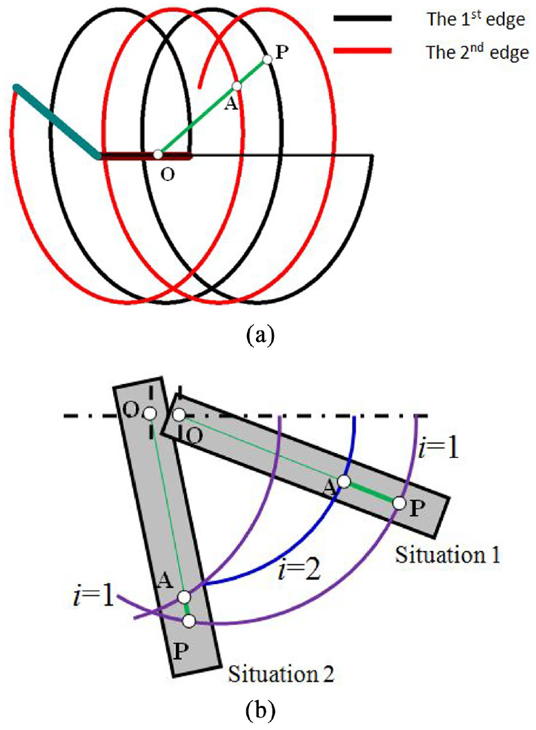
The true IUCT, (a) consider the true trace of the edge (b) with runout.
When the runout effect exists, the current edge may cut the material left by the first previous edge or by itself as in Figure 1(b)). Therefore, calculating all the intersections “

where h is the IUCT value. {

where
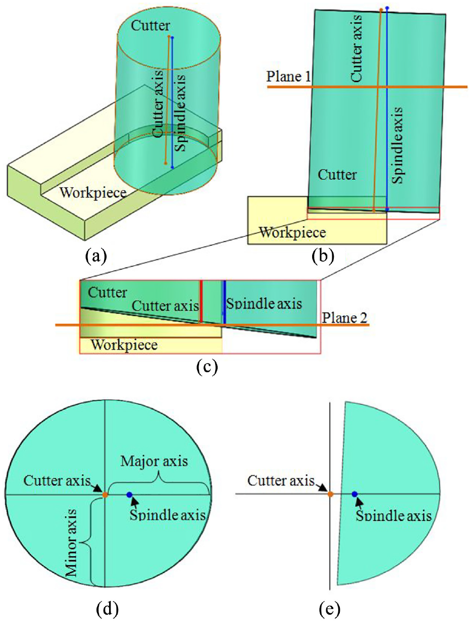
The milling process with cutter runout in micro-milling: (a) axonometric drawing, (b) front view, (c) enlarged drawing of tip, (d) sectional drawing at plane 1, and (e) sectional drawing at plane 2.
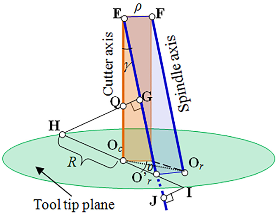
In this case, the cutter rotates around the spindle axis. This kind of runout is distinct from the traditional one. The conventional runout is the parallel lines between these two axes. Obviously, the model in Figure 2 is more common. Just for non-coplanar lines, the sectional views perpendicular to the spindle axis shown in Figure 2(d) and (e) are ellipses. That means one ellipse rotates about the spindle center at any time. Except for the tip in Figure 2(c) and (e), the rotational part about the spindle center is a portion of the ellipse (Figure 2(e)).
Considering the effect of the runout, two coordinate systems are introduced. They are the cutter coordinate system {
(a) Runout offset length ρ: this value is the length of the common vertical line.
(b) Inclination angle γ: the angle is the value between the cutter and the spindle axis.
(c) Cutter axis length Lc: the length is the value between foot point and tip plane along the cutter axis.
(d) Location angle α: this value is the angle between two vectors. One is the xc axis.
(e) Initial rotational angle θ(0): this value is evaluated in the zr

Then, the most important task is to determine the ellipse at any height along the spindle axis as seen in Figure 2. Edges on the ellipse curve are used to compute IUCT value.
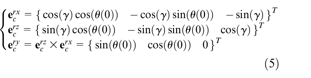
It is vital for expressing the cutter edge in the {
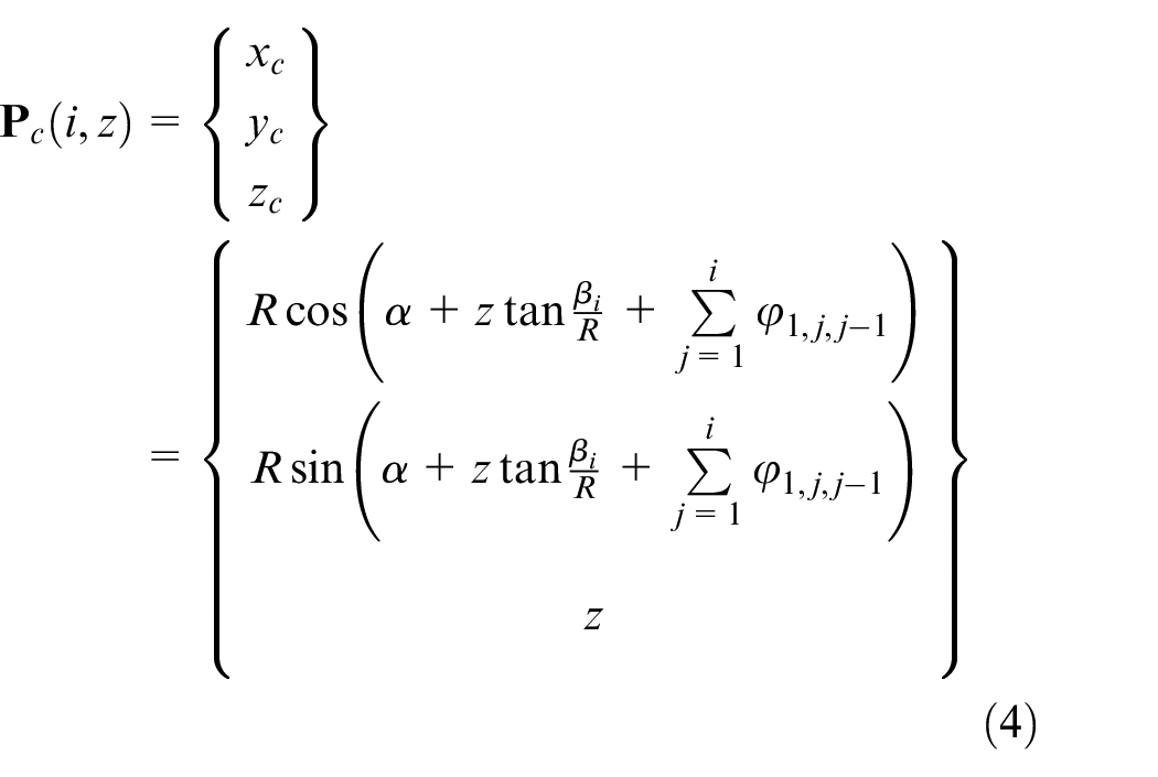
The point at the height z and the edge i is
The origin
Therefore, it becomes the realization for expressing the cutter edges, which are calculated using equation (4), in the {


The next step is to compute the ellipse, which is perpendicular to the spindle axis. The center of an arbitrary ellipse is at the cutter axis. Therefore, the following equation can denote this center

The corresponding rotational center
A truth can be known when a portion of the ellipse rotates about the spindle axis. As seen in Figure 3, when the following equation exists, a part of the ellipse rotates around the spindle center. Otherwise, the whole ellipse rotates about the spindle center
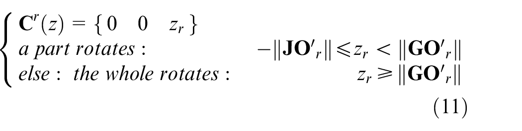

The judgment of the part rotation.
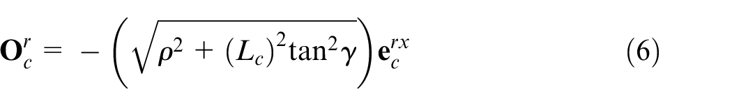
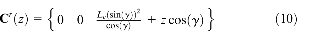
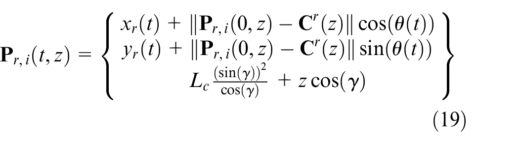
This ellipse is a space curve. The plane containing this ellipse is perpendicular to the spindle axis. The formula below can evaluate a point
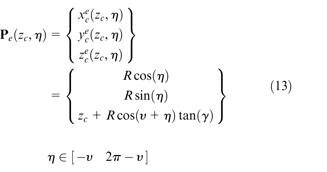
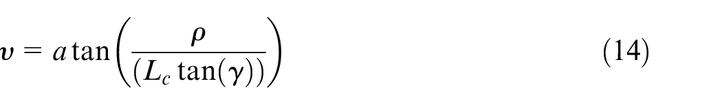
where, in {
Simplifying this equation, a new equation can be obtained

where
When i changes from 1 to N, all the points on the ellipse as well as on the edges are known. In addition, using equation (7), it is easy to compute the expressions of the points

So the trace of the each point in
The set {
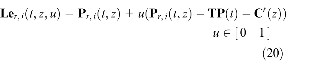
This line is between the point of current cutting edge and the center of the spindle axis at the height z in the {
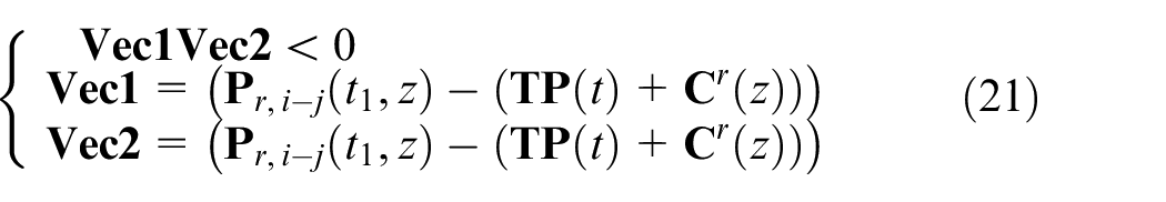
Using equation (21) and the following sketch in Figure 4, the intersection point
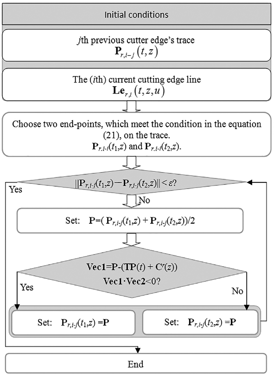
The sketch of computing intersection point.
This sketch can also be used to compute the solution of equation (16). When the set {
The influence of the runout on the IUCT
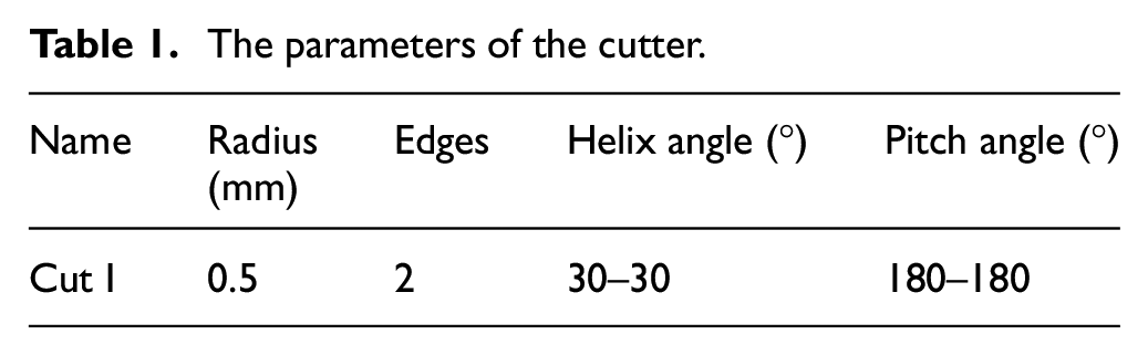
As the cutter radius decreases, the influence of the runout on the IUCT increases. Therefore, this section discusses the effect of the runout. One cutter is selected as in the Table 1. The process is slot milling. The feedrate is 2.5 mm/s. The rotational speed is 18,000 r/min. The edges whose center’s height is 1 mm along the z-axis in the {
The parameters of the cutter.
The liner tool path is selected as

The offset ρ
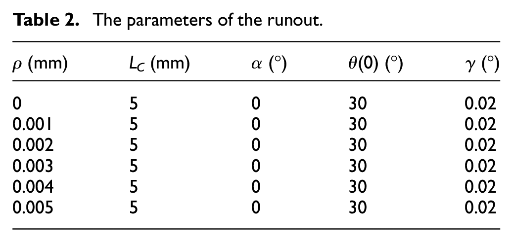
The runout parameters are illustrated in the Table 2. Figure 5 displays the effect of the offset on the IUCT values. The offset increases from 0.001 to 0.005 mm. Meanwhile, the value of the IUCT also increases. However, the wave of the IUCT curve does not translate along the rotational angle direction. This implies that the offset cannot change the position of the IUCT curves but can change the values.
The parameters of the runout.
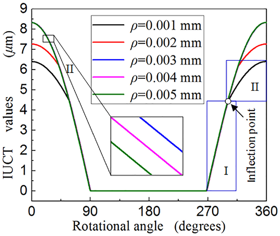
The effect of the offset ρ on the IUCT values.
In addition, when the offset’s value is larger than 0.003 mm, the IUCT values are slightly different. Figure 6 illustrates the reasons. At the same time, as the offset changes from 0 to 0.003 mm, as seen in (a), the material cut by the current edge has that left by the first and the second previous edge. That means the black curve intersects with the red curve. When the offset’s value is equal to 0.003 mm, as seen in (b), the material is cut by the current edge. That means the black curve cannot intersect with the red curve. The more the offset’s value is larger than 0.003 mm, as seen in (c) and (d), the further the black curve departs from the red curve. The current cutter edge only cut the material left by the second previous edge. The greater the offset’s value is, the larger distance that the black curve departs from the red one is when the offset’s value is greater than 0.003 mm. For some cases (ρ = 0.001 mm and ρ = 0.002 mm in Figure 6), the IUCT curves are not first-order continuous ones (these curves have inflection points). These inflection points are the intersection ones of two IUCT curves. The original resource is the difference of the edges’ radius.
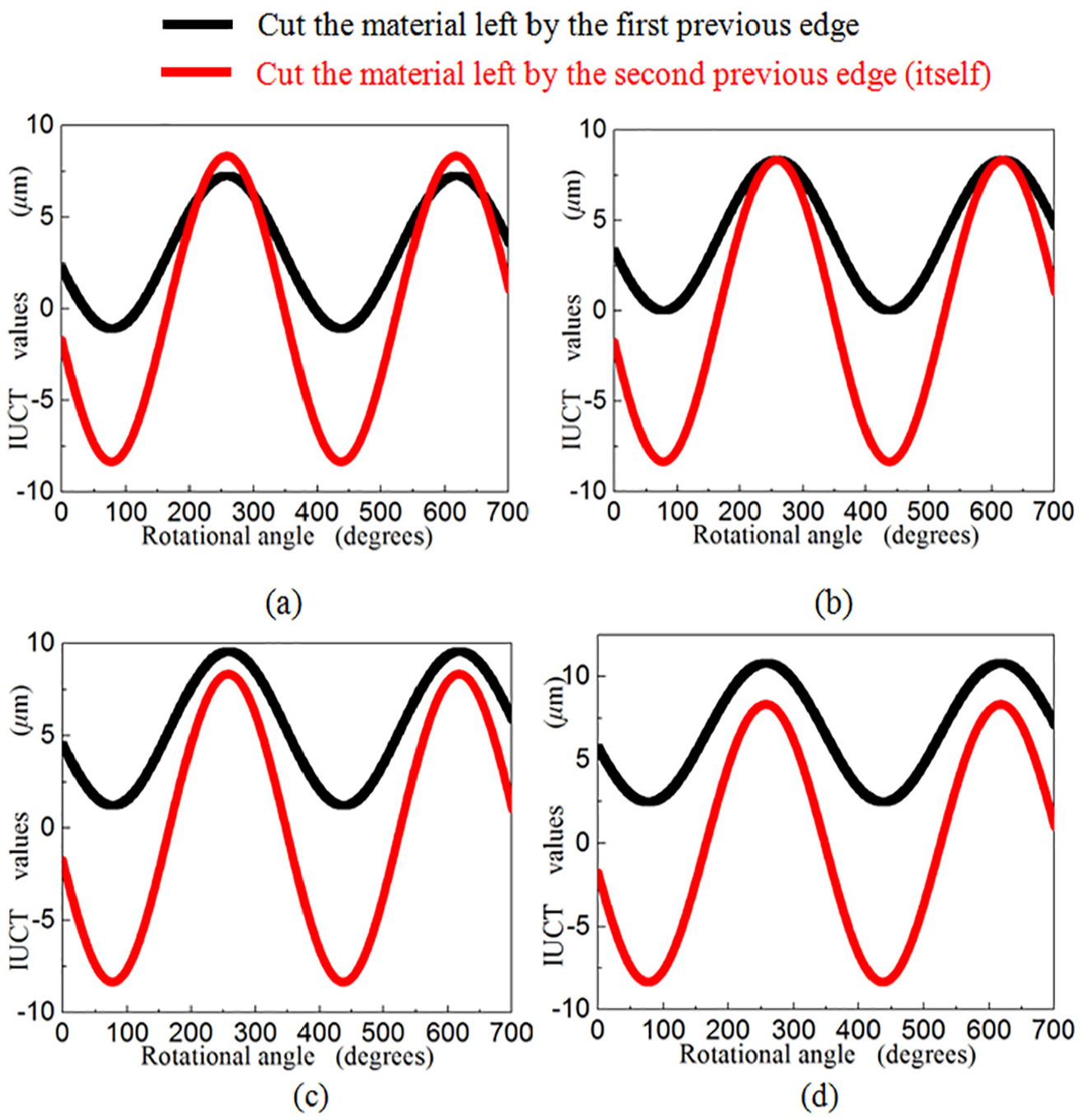
The true IUCT values of the current edge cutting the material left by previous edges: (a) ρ =0.002 mm, (b) ρ = 0.003 mm, (c) ρ = 0.004 mm, and (d) ρ = 0.005 mm.
Inclination angle γ
The offset value is 0.001 mm. The cutter axis length is 5 mm. The location angle is 0°. The initial rotational angle is 30°. The inclination angle has four values: 0.005°, 0.01°, 0.015°, 0.02°.
The IUCT curves for the first edge are calculated and shown in Figure 7. The IUCT values increase as the inclination angle grows larger. Just like the offset’s effect, the inclination angle can change the IUCT value but not change the IUCT’s position. Simultaneously, the inflection points appear in this figure. The reason of this is the same as the one in the above section.
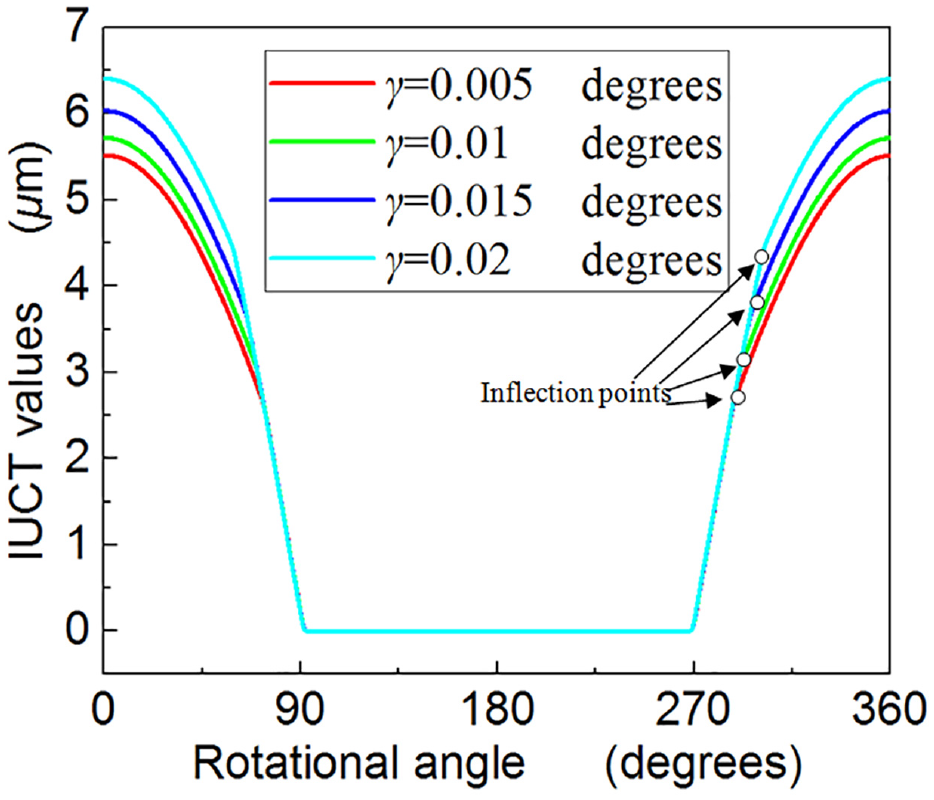
The effect of the inclination angle γ on the IUCT values.
Initial rotational angle θ(0)
The offset value is 0.005 mm. The cutter axis length is 5 mm. The location angle is 0°. The inclination angle is 0.02°. The initial rotational angle has four values: 0°, 20°, 40°, 60°.
Figure 8 shows the IUCT values computed using the mentioned parameters. When the θ(0) changes, the magnitude becomes a constant. Actually, the position of the IUCT lobes translates with the increasing of this angle. The reason is that as the initial rotational angle changes, the radius is not changeable. However, the edges’ positions are changed.
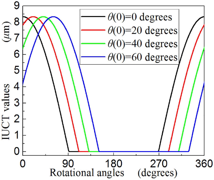
The effect of the initial rotational angle θ(0) on the IUCT values.
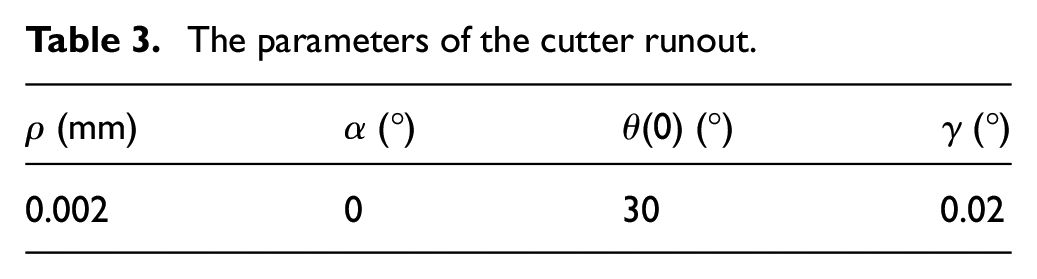
Cutter axis length LC
Table 3 gives the other parameters of the runout. The LC has four values as shown in Figure 9.
The parameters of the cutter runout.
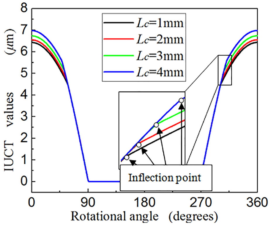
The effect of the cutter axis length Lc on the IUCT values.
When the LC changes from smaller to larger, the magnitude increases simultaneously. Actually, the position of the IUCT lobes does not vary with the increasing of this cutter axis length. The reason is that as the LC changes, the radius is changeable. However, the edges’ positions are not changed. In addition, from this figure, the IUCT curves are composed of two curves. These two curves stand for the material, which is removed by the current edge, is left by the first or the second previous edge.
Location angle α
The runout parameters are the following: the offset value is 0.005 mm; the cutter axis length is 5 mm; the initial rotational angle is 30°; the inclination angle is 0.02°. The location angles compose five values: 5°, 10°, 15°, 20°, 25°.
The IUCT curves are illustrated in Figure 10. When the α changes from 5°to 25°, the magnitudes are constant. In the other words, the value of the location angle has nothing to do with the IUCT magnitudes. However, the location of the IUCT curves translates as the location angle changes. This is similar to the initial rotational angle’s effect. The reason may be as the α changes, the radius is not changeable. However, the edges’ positions move away.
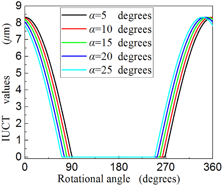
The effect of the location angle α on the IUCT values.
The effect of the non-uniform helix and pitch angle
The cutter has three edges. The helix angles for each edge are β1, β2, and β3. This kind of cutter is cited as the one with variable helix angle. At the bottom of the cutter (the first element), the pitch angles between two adjacent edges are different from each other (φ1,1,2 ≠ φ1,2,3 ≠ φ1,3,1). This is called as the cutter with the variable pitch angle.
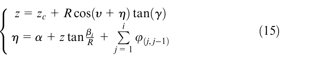
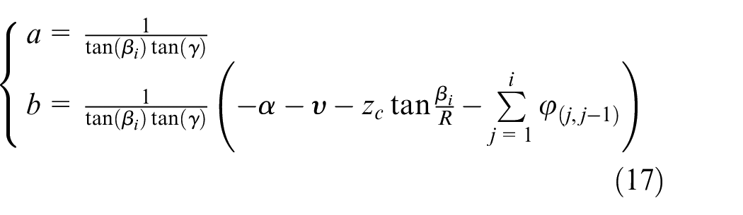
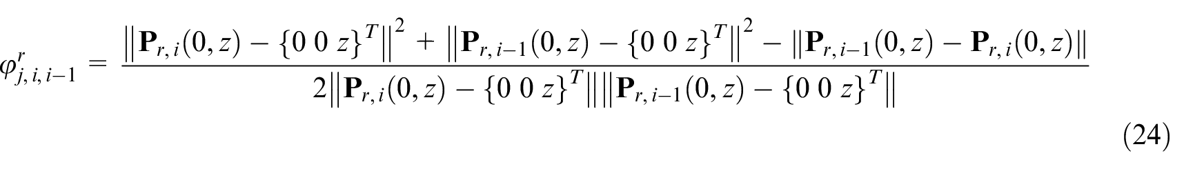
Therefore, when using this kind of cutter, the basic principle is that the pitch angles between two adjacent edges at the height zc (φi,1,2 1,φi,2,3 2,φi,3,1) along the cutter axis are different from each other. The following expression can illustrate the relationship between the parameter z and i without considering the runout effect
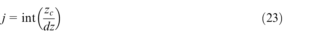
When the runout exists, the theoretical value is not changed. However, the real pitch angles change. The reason is that these values are evaluated in the plane, which is not perpendicular to the cutter axis but the spindle axis. Therefore, the following formula can consider these values with the runout effect
From the above discussion, the helix angles affect the pitch angles and the runout parameters affect not only the pitch angles but also the edges’ radius. Therefore, in order to examine the effect of the non-uniform helix and pitch angle, this section does not consider the cutter runout effect. In the other words, the values of all the runout parameters are zero. Therefore, we choose one cutting element such as the jth element in the Figure 11. In this section, the cutter has two edges. The pitch angles are (180°, 180°), (170°, 190°), (160°, 200°), (150°, 210°), and (140°, 220°). The radius is 0.25 mm. The spindle speed is 18,000 r/min. The feedrate is 0.25 mm/sec. The IUCT values for the first edges are computed.
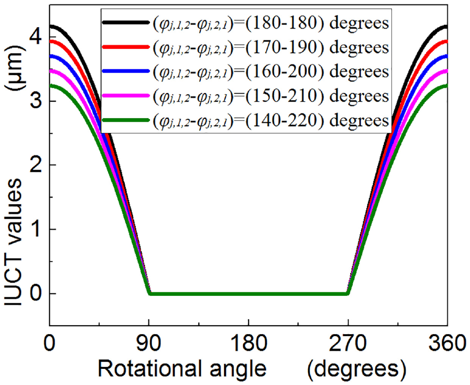
The effect of the variable pitch angles on the IUCT.
Figure 11 shows the results under the above conditions. The position of the IUCT values curves does not translate. However, the values change with the increase in pitch angles φj,1,2. The reason for this is that when the values of the φj,1,2 are 180°,170°,160°,150°, and 140 , the feedrates for the first edge are 0.0042, 0.0039, 0.0037, 0.0035, and 0.0032 mm. As a result, the IUCT values for this edge become smaller and smaller.
When the feedrate per tooth becomes smaller and smaller, the second edge can only remove the materials left by the first previous edge (i = 1). If we want to compute the first cutter edge’s IUCT values, the IUCT curve must have the inflection points due to that this edge cut the material left by both edges.
It should be noted that the helix angles affect the IUCT values through pitch angles’ effect.
Verifications
This section proposes a series of experiments, which are conducted in the literature, 12 to verify the proposed IUCT model. These experiments adopt a high-precision vertical milling machine with a 22-kw spindle drive motor. The rotational speed changes from 5000 to 30,000 r/min. In this literature, a Kistler 9256A, a three-channel piezoelectric dynamometer, measures the cutting forces. The material of the workpiece is pure copper. The micro cutter has two edges. The radius is 0.5 mm. The helix angle is 30°–30°. The shank taper angle for this micro mill is 16°.
The spindle speed is 18,000 r/min. The up-milling process is selected. The minimum undeformed thickness is 1.2 μm. The other parameters have two groups.
Group 1: axial depth 150 μm, radial depth 225 μm, feedrate 150 mm/min
Group 2: axial depth 120 μm, radial depth 300 μm, feedrate 150 mm/min
Table 4 shows the cutting force coefficients and runout parameters for these two groups.
The runout parameters and the force coefficients.
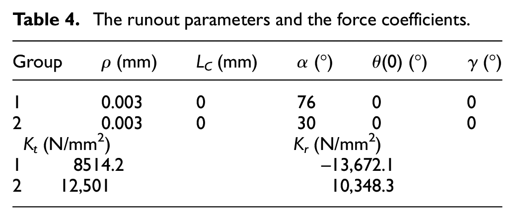
This article chooses the following cutting force model
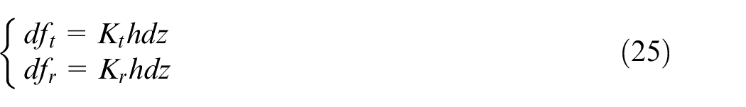
where the parameters
Figure 12 presents the results. The results show the comparisons of two tests (group 1 and group 2). The x- and y-direction forces are plotted. The figures illustrate that the values computed using the presented method are closer to the real one. The reason for this is that the proposed method is based on the accurate IUCT values. The method in the literature is simplified. The errors for these two methods can be computed. For group 1, the error along x-direction is approximately 2.5%. This value in the literature is about 3.55%. The error of y-direction is about 3%. This value for the literature is about 3.69%. For group 2, the errors in the literature along x- and y-directions are 4.01% and 12.44%. However, these values for the introduced method are about 3.44% and 8.7%, correspondingly. In conclusion, the proposed method provides higher accuracy.
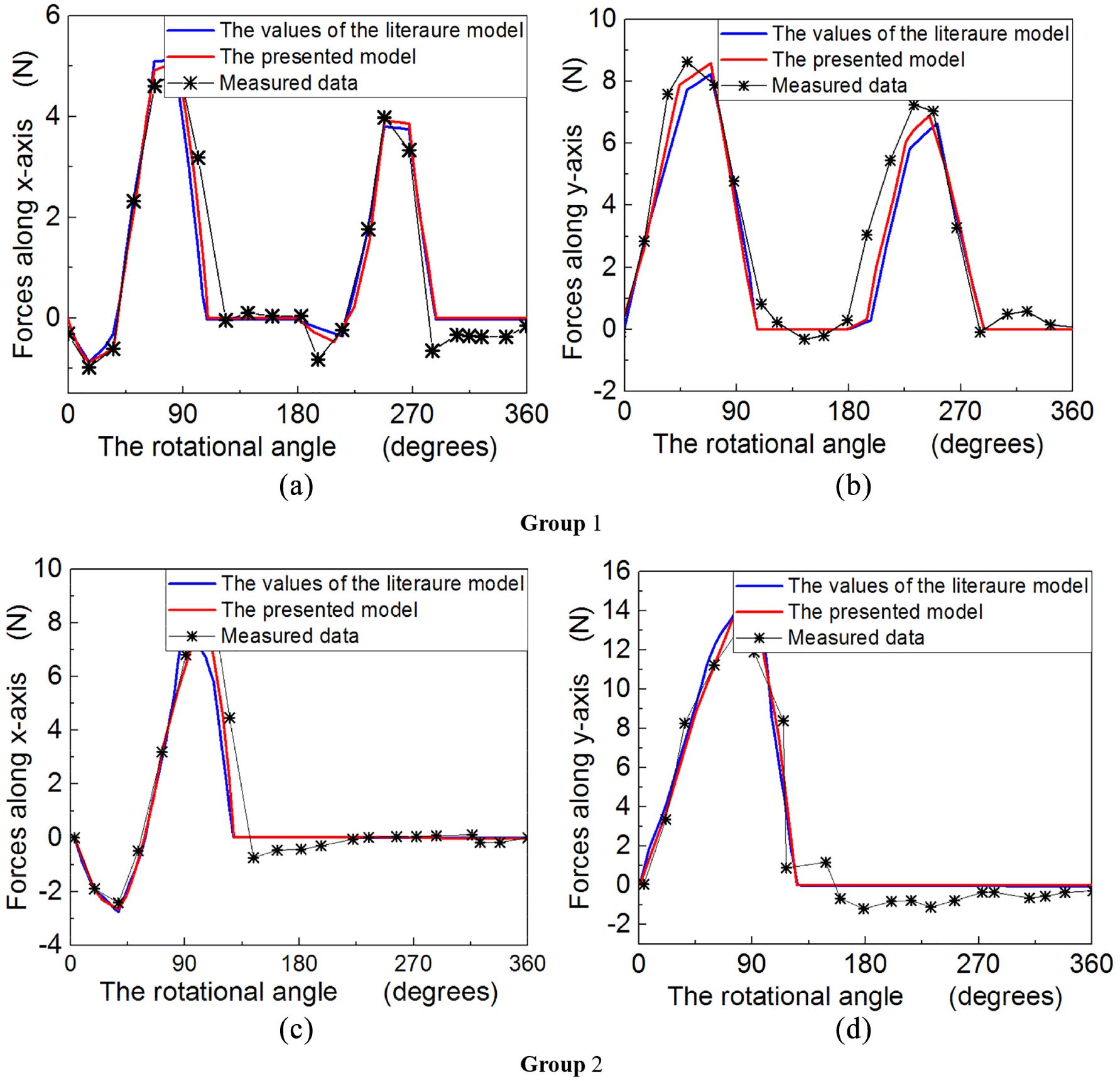
The cutting forces comparison between the proposed method and the one in the literature: 12 (a) x-direction for group 1, (b) y-direction for group 1, (c) x-direction for group 2, and (d) y-direction for group 2.
Conclusion
As a key factor of the force model, the accuracy of the instantaneous undeformed thickness model determines the force-predicting precision. In addition, the runout effect in micro-milling affects the machining process more significantly compared with macro milling. Furthermore, modern industry uses the cutters with non-uniform helix and pitch angles more and more frequently for their excellent properties. These bring difficulties to build the IUCT model. An IUCT model is presented regarding cutter runout and variable pitch and helix angles in the micro-milling process. The cutter edge with the cutter runout effect is modeled. Then, the intersecting ellipse between the plane vertical to the spindle axis and the cutter surface which is a cylinder can be gained. Based on this, the points, which are used to remove the material, on the ellipse as well as cutter edges are calculated. The true trochoid trajectory for each cutting point along the tool path is built. Based on this, the study builds an accurate IUCT model. Subsequently, the research analyzes each parameter’s effect on the IUCT values. After that, helix and pitch angles’ effects on the IUCT values are studied. The last section verifies the correctness and validity of the IUCT model based on the experiment conducted in the literature. The largest prediction error is about 8.7% compared with 12.44% in the literature. In future studies, how to detect runout parameters becomes one of our research directions.
Footnotes
Appendix 1
Actually, when the tool is deflected, the instantaneous uncut chip thickness’s (IUCT) calculation process must adopt a new cylinder surface in Figure 13. This surface is changed as
In real machining process, the tool profile after deformation is like in Figure 13(a); it is difficult to compute IUCT. Therefore, we use Figure 13(b) to stand for (a). We can adopt the following steps.
The cutter edge after deformation can be expressed as
Then, using equation (7) and below theory, the IUCT combined with cutter deformation can be obtained.
Declaration of conflicting interests
The author(s) declared no potential conflicts of interest with respect to the research, authorship, and/or publication of this article.
Funding
The author(s) disclosed receipt of the following financial support for the research, authorship, and/or publication of this article: This research is supported by the National Natural Science Foundation of China (Grant No. 51605147, 51575163), National Science Fund for Distinguished Young Scholars of Henan Polytechnic University, and young backbone Project of Henan Polytechnic University (No. 2018XQG-05).