
Abstract
An enhanced time-domain simulation method of cutter/workpiece dynamic engagement during milling process is proposed in this article, which comprehensively considers the effect of multi-order modal characteristics of cutter system and cutter runout including offset and inclination. Based on the cutter dynamic displacement response, this article further presents the machined surface reconstruction algorithm and evaluation method for the form error. This research systematically studies and compares the calculation accuracy between the proposed method and other previous three kinds of methods. The effectiveness of the proposed method has been verified by a series of milling experiments successfully. By comparing with the other three methods, the proposed method shows a high calculation performance, especially under the milling condition with a large axial depth of cut and low damping or stiffness of cutter system. Besides, the results indicate that the form error has a strong dependence characteristic on the milling parameters, particularly on spindle speed. Additionally, cutter runout would easily cause over cut phenomenon on the machined surface and seriously deteriorate the surface roughness.
Introduction
With the continuous improvement of the part quality requirement, how to obtain a high precision machining has become an important challenge for the manufacturing process. In order to improve the machining quality and save the manufacturing cost, virtual simulation technology 1 of machining process has been gradually applied to study the relationship between the machining parameters and part quality, and it further helps manufacturer to choose reasonable process parameters. At present, as one of the main methods of metal cutting, the machining quality in milling process has been studied by a lot of researchers.
During milling process, the tool/workpiece engagement process is the superimposed result of the macroscopic relative motion between the cutter and workpiece and the micro-amplitude vibration induced by milling force, which leads to the actual machined surface deviating from its desired position and thus producing the form error. In order to study the form error, it is necessary to reconstruct the machined surface based on the vibration response of cutter and workpiece through theoretical or experiment method. For the form error during milling process, there are mainly four kinds of different methods. The first method is the cutter/workpiece geometric engagement method, which ignores the system dynamic excitation and response caused by milling force and has been mainly used to analyze the surface roughness. Based on the geometric relative motion between cutter and workpiece, Gao et al. 2 presented a numerical simulation method for machined surface topography during milling process with flat- and ball-end cutter. Arizmendi et al.3,4 studied the effect of cutter runout on surface roughness in peripheral milling, especially analyzed the position and width of heterogeneity band and the characteristic of roughness distribution along cutter axis direction. Corral et al. 5 discussed the influence of feed, eccentricity and helix angle on machined surface topography in side milling processes. Later, Corral et al. 6 applied the same method to study the surface reconstruction algorithm with ball-end cutter, and emphatically researched the effect of feed per tooth and radial depth of cut on surface roughness, and gave out the strategy for improving the machining efficiency.
The second one is the static deflection method, which considers the static excitation effect by milling force. In early studies, Kline et al. 7 analyzed the influence of cutter static deflection on machining accuracy during milling process based on the mechanistic cutting force model. DeVor and Sutherland 8 further improved this method, in which the feedback effect of cutter deflection on cutting load is considered. Altintas and Lee 9 applied the cutter static deflection method and concluded that the variable-pitch helical end mills can increase the machining accuracy of machined surface by 10%–20%. Law and Geddam 10 studied the form error in straight line milling and corner milling during rough and finishing operations. Yun et al. 11 constructed the three-dimensional (3D) surface error map by obtaining the cutting edge position at which the flutes pass over the machined surface. Ryu et al.12,13 built a form error calculation model and discussed the variation of error topography under different milling parameters and milling types. Dedai and Rao 14 presented a classification method of form error profile corresponding to milling parameters, which was further to be used for error prediction during curved surface milling. During ball-end milling of inclined convex and concave surfaces, Gök et al. 15 calculated the tool deflections depending on cutting force acting on the cantilever beam model of cutter. For workpiece static deflection, Ratchev et al. 16 reported on a new simulation methodology of static deflection of thin-wall parts during machining based on finite element method (FEM), which was further used for compensation of poor geometric accuracy. Bolar and Joshi 17 proposed a 3D workpiece static deflection method, which provided very useful insights into the complex physical interaction of cutter and workpiece.
Different from the first two methods, the third one is the harmonic balance method based response directly solving method, which considers the dynamic response of cutter and workpiece induced by milling force. Hence, the advantage of this method is that the dynamic excitation characteristics of milling force with harmonic components depended on spindle speed are considered. In this method, it is necessary to have a prior-knowledge about the milling force. Montgomery and Altintas 18 early proposed the simulation and analysis method for machining surface topography based on milling dynamics. Then, the influence of cutter eccentricity and system dynamic response on the surface error morphology is further analyzed in their studies. 19 Ismail et al. 20 put forward a generation model of machined surface, in which the cutter runout, vibration and wear were comprehensively considered. Schmitz and colleagues21,22 gave out a closed-form solution for cutter displacement response and pointed out that the cutter runout would affect the roughness and surface location error. Yuan et al. 23 analyzed the surface topography and surface location error based on the harmonic balance method, in which the influence of feed per tooth, runout and number of cutter teeth on topography was discussed. Denkena et al. 24 reconstructed the cutter actual motion and extracted the form surface morphology based on the measured milling force data and the frequency coupling dynamic model of tool system. Besides, Jiang et al., 25 Arizmendi et al. 26 and Moreau and Costes 27 researched the machined surface and form error through the measured cutter vibration response.
The last one is the time-domain simulation method based on cutter/workpiece dynamic engagement process. As the cutter/workpiece engagement process exist the force–displacement coupling effect, it is necessary to consider this kind of coupling effect for obtaining high simulation accuracy. With the aid of time-domain simulation, Zhang et al. 28 presented an integrated model of feed drive system with milling process and pointed out that the displacement fluctuation has an important effect on the contour roughness. Surmann and Enk 29 and Surmann and Biermann 30 predicted the transient behavior of cutter vibration along changing engagement conditions, which can allow the feedback effect of cutter displacement into the cutter/workpiece engagement and thus on chip form, and then constructed a geometric model of machined surface with the knowledge of tooth vibration trajectory. Schmitz 31 focused on the time-domain simulation method and applied the surface location error (SLE) to evaluate the machining quality.
The above literature views show that a great improvement about form error during milling process has been made, but what should be pointed out is that there also exist some disadvantages in these methods. First, all the four kinds of methods can be used to study the machined surface topography and form error, but the application ranges of these methods are not given out, especially the comparison of superiority among them is ignored. Besides, as a flexible system, the cutter system, being not a single-degree-of-freedom (DOF) dynamics model, includes multi-order modal characteristics in fact. Especially under the milling condition with a large axial depth of cut, the multi-order modal characteristics will become prominent, which should be considered. Finally, cutter runout is an important factor to affect the machining quality, but its influence cannot be taken into account effectively. Hence, this article presents an enhanced time-domain simulation method for cutter/workpiece engagement process with consideration of the multi-DOF cutter dynamics model and cutter runout and systematically compares the calculation accuracy between the proposed method and other previous methods. The contents of this article are organized as following. In section “Simulation method of machined surface topography during milling process”, this article gives out the simulation method of machined surface topography during milling process, which includes the proposed method and other three kinds of methods, and then presents the reconstruction algorithm of machined surface. In section “Simulation and experiment verification”, a series of milling tests are conducted to verify the effectiveness of the proposed method. In section “The influence of different milling conditions on form error”, the influences of milling parameters, cutter runout, milling types, tooth helix angle, damping and stiffness of cutter system and multi-DOF cutter dynamics model on form error are discussed, respectively.
Simulation method of machined surface topography during milling process
Definition of cutter runout
Figure 1 is the parametric description model of cutter runout.

General definition of cutter runout.
In the cutter geometry coordinate system, the geometry shape of tooth cutting edge of the jth cutting disk element on the ith tooth is expressed as
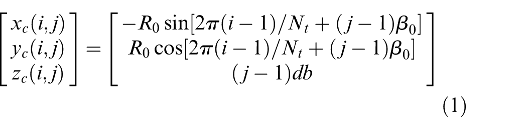
where
Then, in the cutter rotation coordinate system, the tooth cutting edge can be derived as

where
Solving cutter displacement response and modeling tooth trajectory
This subsection mainly proposes a time-domain simulation method for cutter/workpiece dynamic engagement process with consideration of multi-DOF modal characteristics of cutter system and cutter runout, solves the cutter displacement and builds up the tooth trajectory model. Then, other three kinds of modeling methods for the tooth trajectory are also given briefly.
Method 1: cutter/workpiece dynamic engagement–based time-domain simulation method
In the proposed method, as shown in Figure 2(a), the milling process assumes that the cutter is flexible and the workpiece is rigid. The machined surface will deviate from the desired surface resulting from the excitation of milling force on cutter system. In order to analyze the cutter vibration, the cutter system is assumed as a multi-DOF dynamics system with a series of lumped mass nodes shown as the green nodes in Figure 2(a), and the cutter/workpiece engagement process of the jth disk element on section A in Figure 2(a) is further detailed in Figure 2(b). Here,
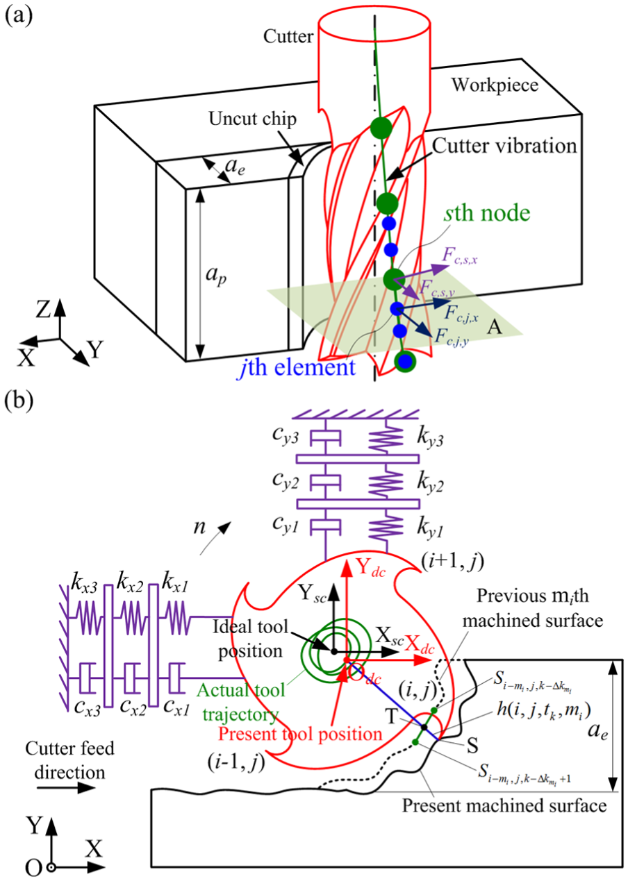
(a) Milling process and (b) cutter/workpiece dynamic engagement.
In physical space, the dynamic equation of the flexible cutter system is

where
Based on modal analysis theory, in modal space, the dynamic equation of the flexible cutter system can be given by

where
During the cutter/workpiece engagement process, there exists a coupling effect between milling force and cutter displacement, and the instantaneous uncut chip thickness is the most important parameter for presenting this kind of coupling effect. In the proposed time-domain simulation method, first, the continuous time is discretized into a time sequence with an interval of
where
At current time, the instantaneous uncut chip thickness

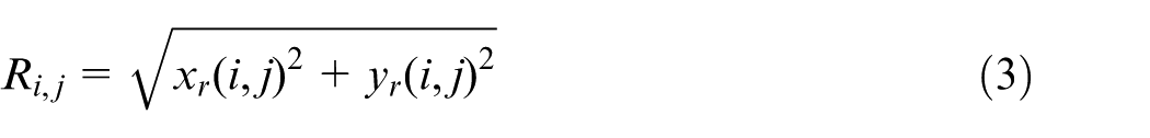
Furthermore, calculating the distance between point
where
Combining the mechanistic cutting force model and the calculated instantaneous uncut chip thickness, we can further achieve the milling force of each cutting disk element of cutter at current time
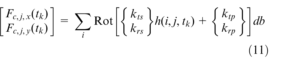
where
where

where
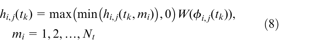
With the aid of the response
After obtaining the cutter displacement response at time
Method 2: harmonic balance method based response directly solving method
Unlike the method 1, method 2 calculates the cutter displacement response using the harmonic balance method with the aid of pre-calculated milling force and cutter dynamics. In this method, the dynamic engagement process between cutter and workpiece is ignored.
Considering the cutter runout and tooth trochoid trajectory, the possible instantaneous uncut chip thickness during cutter/workpiece geometric engagement can be shown as equation (15), which is detailed in Zhang et al. 32
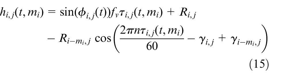
where
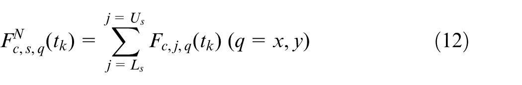
Combining equations (8)–(12), we can also obtain the milling force. In the harmonic balance method, the milling force acting on DOF nodes of cutter is expressed as a Fourier series expansion
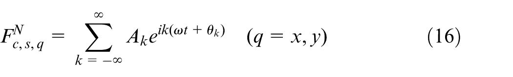
where
where
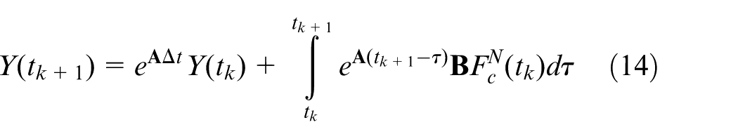
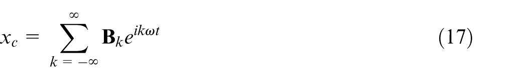
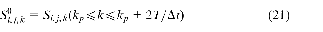
Substituting equations (16) and (17) into equation (4), we can further obtain
Then,

where
Finally, the cutter displacement response can be acquired by substituting equation (19) into equation (17), and the tooth trajectory can be also calculated with the aid of equation (6).
Method 3: cutter static deflection method
In this method, the cutter displacement is only calculated based on its static deflection, and the dynamic response of cutter system is not considered in this model. Here, the calculation procedure of milling force is the same with method 2. Then, the static deflection of cutter can be shown as equation (20), and the tooth trajectory can be also obtained

Method 4: cutter/workpiece geometric engagement method
For method 4, the dynamic excitation of milling force for cutter system is not considered, and the cutter/workpiece engagement process is only based on the geometric constraint between them. At this moment, the dynamic response of cutter system is zero. Hence, let
Machined surface reconstruction algorithm
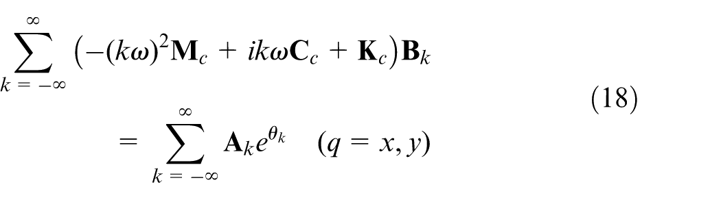
The machined surface is the result of the intersection between tooth trajectory surface and the workpiece. As shown in Figure 3(a), the actual machined surface
(a) Actual machined surface and desired surface and (b) machined surface reconstruction.
In order to analyze the form error, the actual machined surface should be described in the global coordinate system, and the sampling point on it should also be corresponded to the regular points on the desired surface
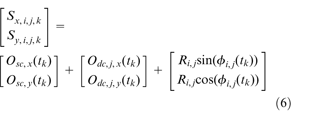
As shown in Figure 3(b), the point
Step 1. For a given point
where
Step 2. Determine the point
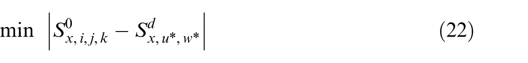
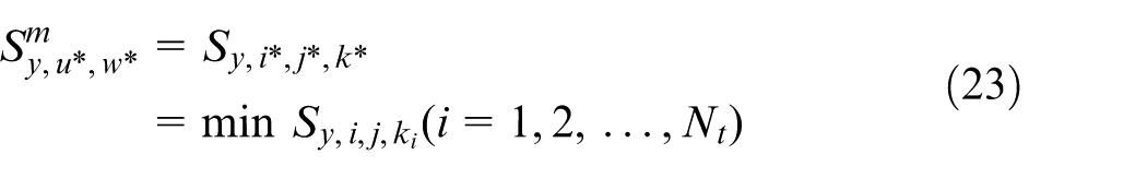
Step 3. As shown in equation (23), let the point with smallest coordinate in Y direction be the point

Step 4. By repeating above steps (1–3), find out corresponding points on the machined surface for all given points on the desired surface, and finally, the actual machined surface can be reconstructed.
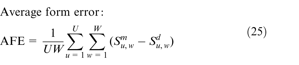
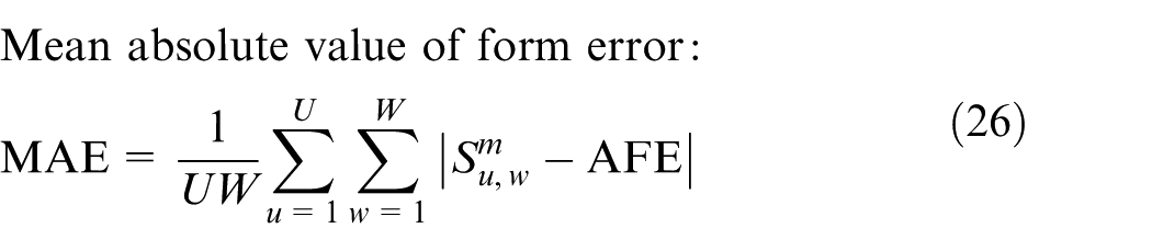
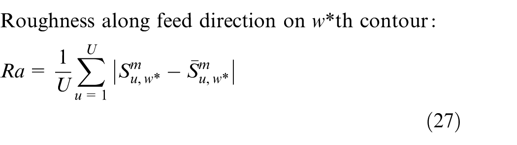
Form error evaluation
After obtaining the machined surface
Simulation and experiment verification
Experiment setup
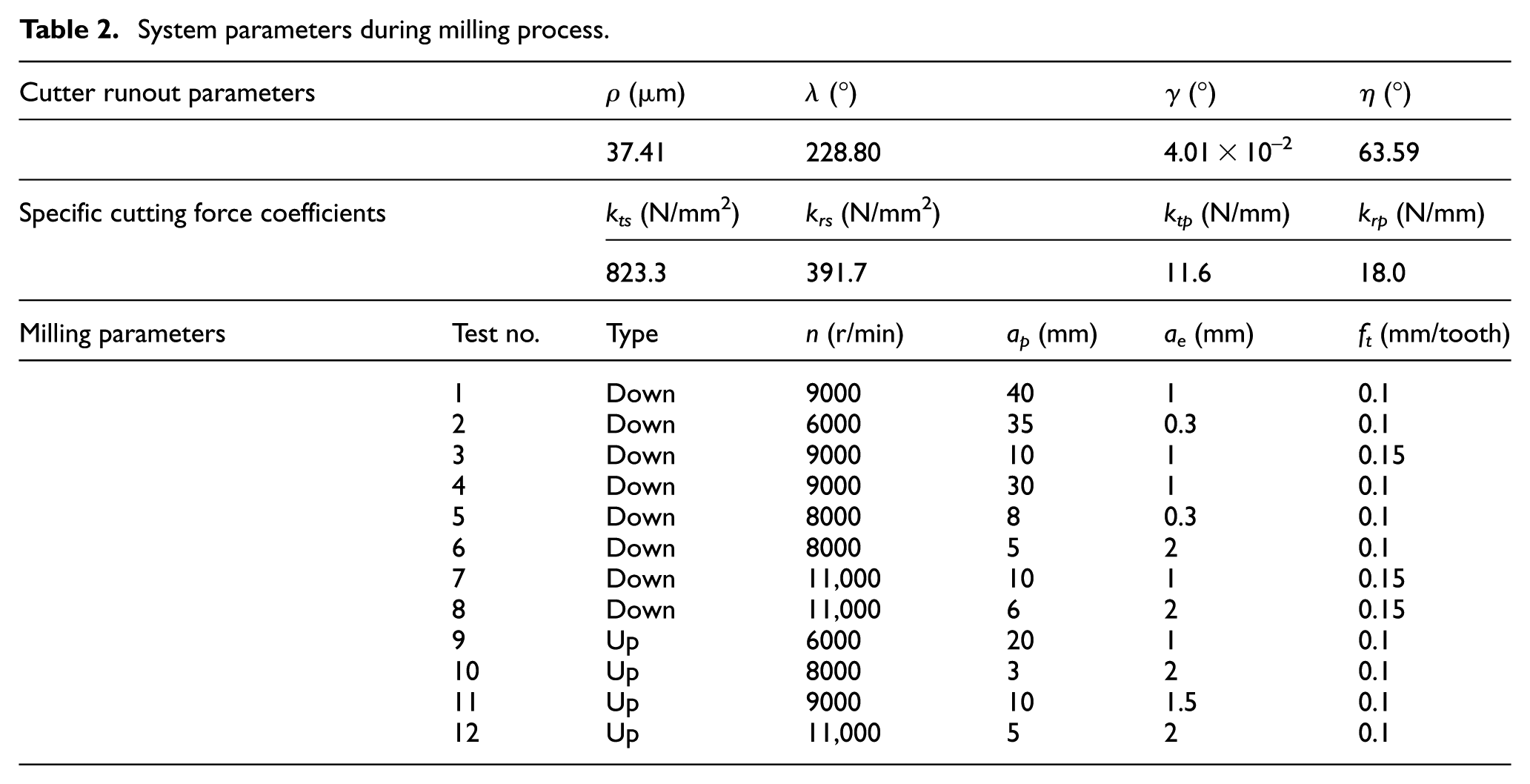
In this section, a series of milling tests are conducted to verify the effectiveness of the proposed method. As shown in Figure 4, a machining center and a three teeth carbide tool with a diameter of 16 mm, a helix angle of 45° and an overhang length of 80 mm are used in the milling tests. The workpiece material is aluminum alloy 7050. For the milling condition with a large axial depth of cut, in order to accurately reflect the dynamic characteristics of the cutter system and calculate the displacement response of the cutter, the cutter system is assumed as a multi-DOF flexible system. The experiment modal analysis with least mean square (LMS) is used to identify the modal parameters of cutter system. As shown in Figure 4, there exist five nodes in X and Y directions, and the DOF nodes are located at the axial position of 0, 10, 20, 30 and 40 mm from the bottom of cutter. Table 1 contains the identified results of modal parameters including natural frequency, damping ratio and mass-normalized shape. For comparison, this article also assumes the cutter system as a single-DOF dynamic system. At this moment, the modal parameters are identified using the dominant modal of the origin frequency response function (FRF) of the first node. During the milling process, 12 milling tests with its parameters are given in Table 2, in which the cutter runout parameters and the specific cutting force coefficients calibrated based on the thin-plate milling experiment 33 are also determined. After the milling, the machined surface contour is measured by a contacting aspheric surface contour measurer, the measurement resolution and speed of which are 0.125 μm and 1 mm/s, respectively.
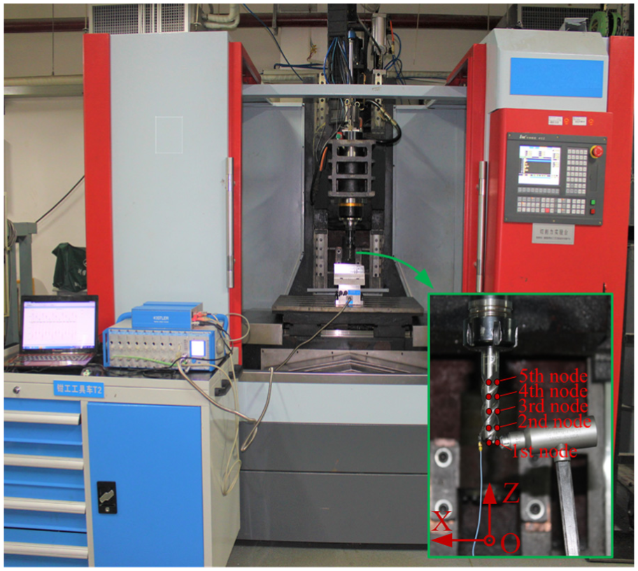
Milling experiment setup.
Modal parameters of cutter system.
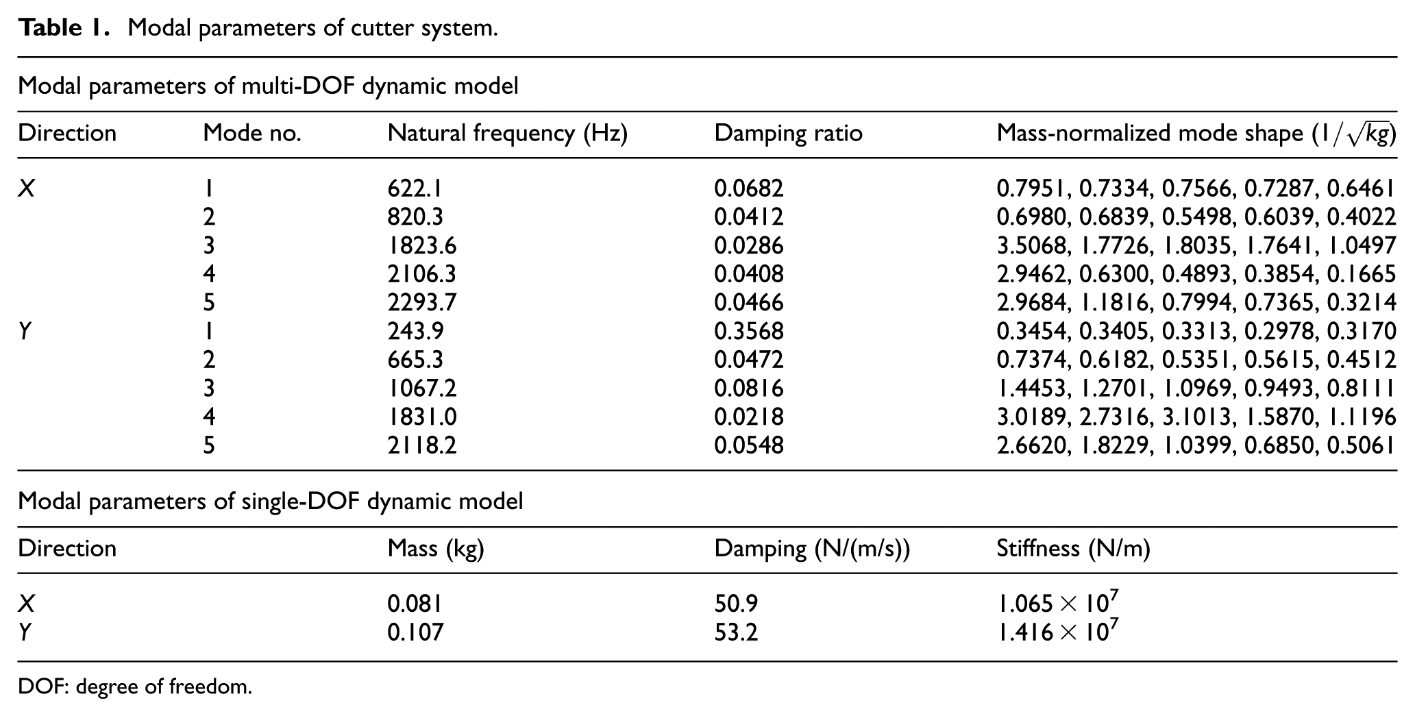
DOF: degree of freedom.
System parameters during milling process.
Simulation and experiment results
Figure 5(a)–(d) is the simulated results of machined surface topography and form error with the milling parameters in test 1 of Table 2 using the four kinds of simulation methods, respectively. It can be seen that the form error has an evident fluctuation in the cutter axis direction, but the variation in the feed direction is small. The form error distribution of different methods is different. During down milling process, the positive value of form error means under cut, and negative value of form error means over cut. During up milling, the conclusion is just the opposite.
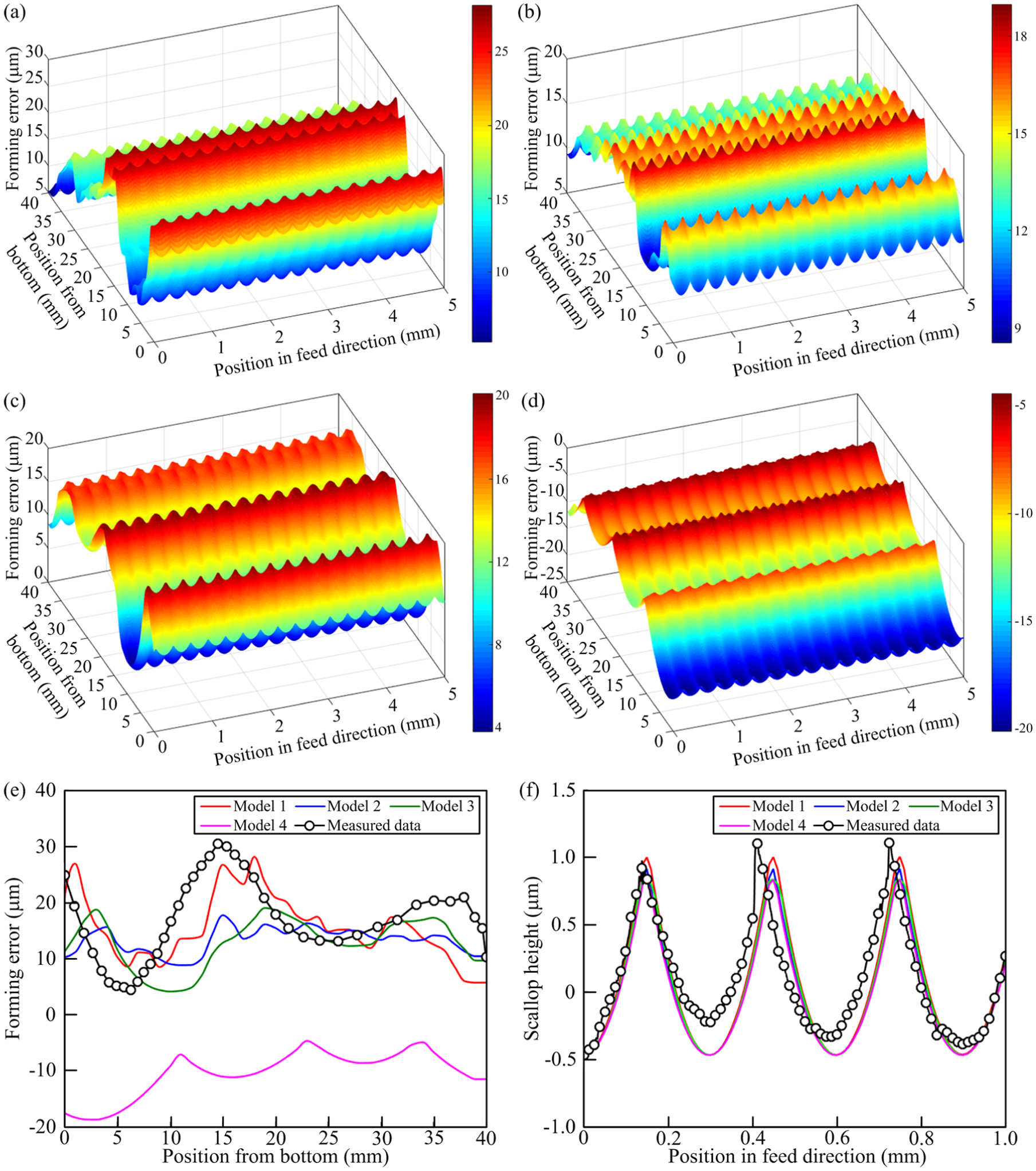
Simulated and measured form error of Test 1: (a) method 1, (b) method 2, (c) method 3, (d) method 4, (e) simulated and measured data of form error along cutter axis direction and (f) simulated and measured data of scallop height along feed direction
For further analyzing, Figure 5(e) shows the simulated and measured data of form error distribution along the cutter axis direction. Here, we can see that the result of method 1 has a good agreement with the measured data, the results of method 2 and method 3 have a slight distinction compared with the measured data, and there exists a large difference between method 4 and the measured data. The reason for the conclusion is that method 1 considers the tool/workpiece dynamic engagement process, which is more accordant with the actual situation. Method 2 and method 3 ignore the force–displacement coupling effect during cutter/workpiece engagement process, especially method 3 applies the cutter static deflection as the cutter response. Hence, both of them will not reflect the actual cutter response accurately. Only considering the cutter/workpiece geometric engagement, the simulated result of tooth trajectory in method 4 is mainly influenced by the cutter runout. As the cutter runout increases the cutting radius, the machined surface is easily to be over cut. Compared with other three kinds of methods, only method 4 shows the form error as a negative value. Figure 5(f) shows the simulated and measured data of scallop height distribution along the feed direction, and the height position of the contour is located at 1 mm from cutter bottom. The result indicates that the simulated data agrees with the measured one both in variation trend and amplitude. Besides, data variation period is about 0.3 mm, which is equal to the feed per revolution but not feed per tooth. This is because some teeth lost cut during the exit stage resulting from the existence of cutter runout.
Similarly, Figure 6 is the simulated and measured data of form error with its milling parameters given in test 2 of Table 2. From Figure 6(a)–(d), it can be concluded that the form error shows a large variation along cutter axis direction under the effect of cutter runout and dynamic excitation of milling force. Compared with other three kinds of method, the result of method 1 is much closer to the measured data. Besides, as only considering the geometric engagement process between cutter and workpiece, the simulated result of method 4 in Figure 6(e) is the same with that of Figure 5(e) at the same height position, but there is a large difference for the other three methods when the parameters are different, which means that the milling parameters have an important influence on form error. What’s more, the simulated and measured results of scallop height are also very close.
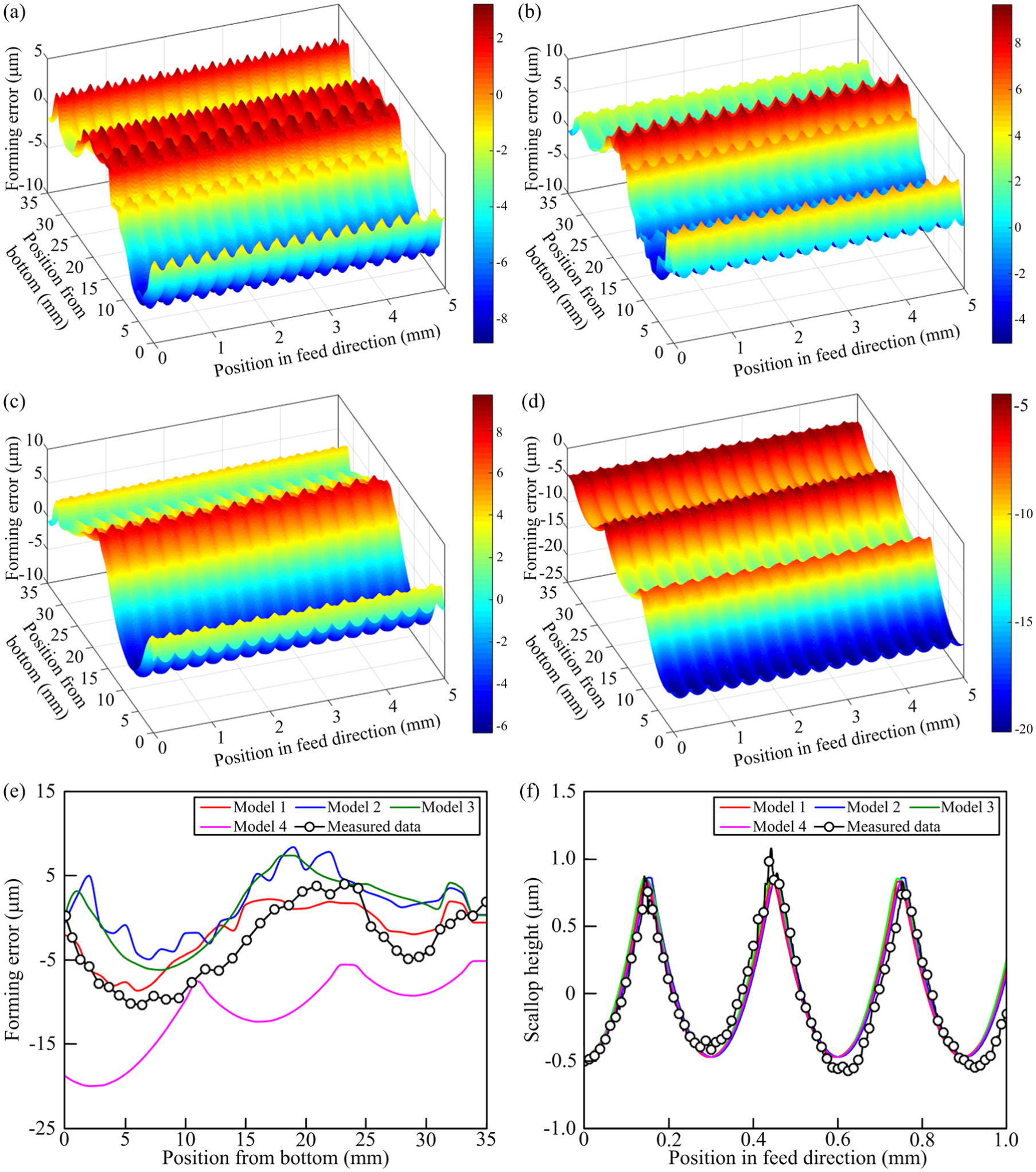
Simulated and measured form error of Test 2: (a) method 1, (b) method 2, (c) method 3, (d) method 4, (e) simulated and measured data of form error along cutter axis direction and (f) simulated and measured data of scallop height along feed direction.
Finally, Table 3 gives out the evaluation results of form error of the above two milling tests, which includes the average form error (AFE), the mean absolute value of form error (MAE) and the contour roughness Ra. Similar to the above analysis results, the quantitative results show that the method 1 has higher prediction accuracy in predicting the form error when compared with other three kinds of methods. Table 4 further compares the measured data of form error with the predicted one based on method 1 from test 3 to test 12. The comparison indicates that the results of method 1 have a good agreement with the measured values.
Evaluation results of form error.
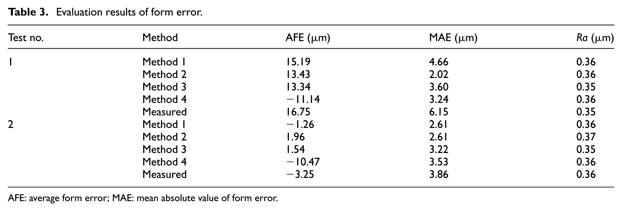
AFE: average form error; MAE: mean absolute value of form error.
Form error comparison between measured and predicted data with method 1.
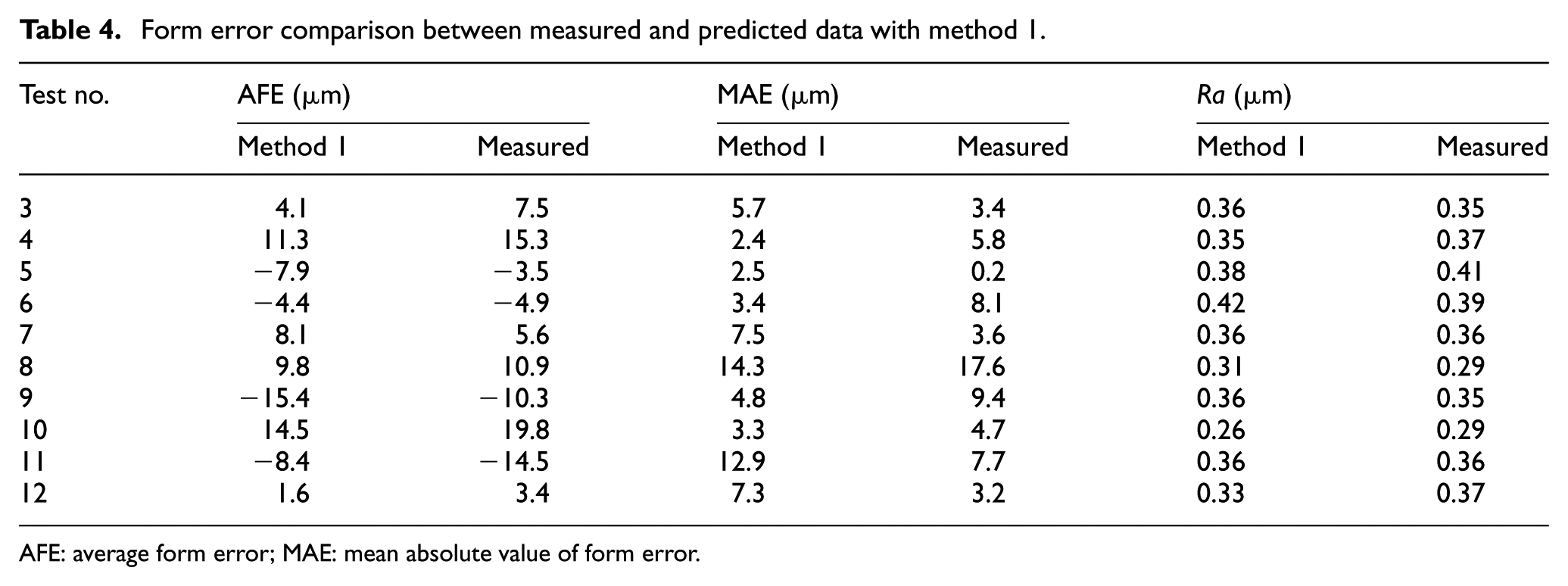
AFE: average form error; MAE: mean absolute value of form error.
The influence of different milling conditions on form error
This section focuses on the influence of different milling conditions on the form error through simulation and experiment studies. In order to analyze the influence trend more conveniently, the first four subsections only apply the single-DOF dynamics model of cutter system with its modal parameters given in Table 1 to study the effect of milling parameters, cutter runout parameters, milling type and dynamics parameters of cutter system, respectively, while the last subsection analyzes the distinction between single-DOF and multi-DOF dynamics model of cutter system.
The influence of spindle speed n and radial immersion ratio aD on form error
Figure 7(a) and (b) is the simulated results of AFE and Ra under different spindle speeds n and radial immersion ratios aD using method 1 without cutter runout effect, respectively. The machining parameters during the down milling are axial depth of cut ap = 1 mm and feed per tooth ft = 0.1 mm/tooth. It can be seen that the AFE and Ra show an evident fluctuation within the whole parameter field, which means that the AFE and Ra have a strong dependence on the milling parameters. Besides, both AFE and Ra have multiple local extrema, and the position of these extrema makes the combination of spindle speed and radial immersion ratio change linearly.
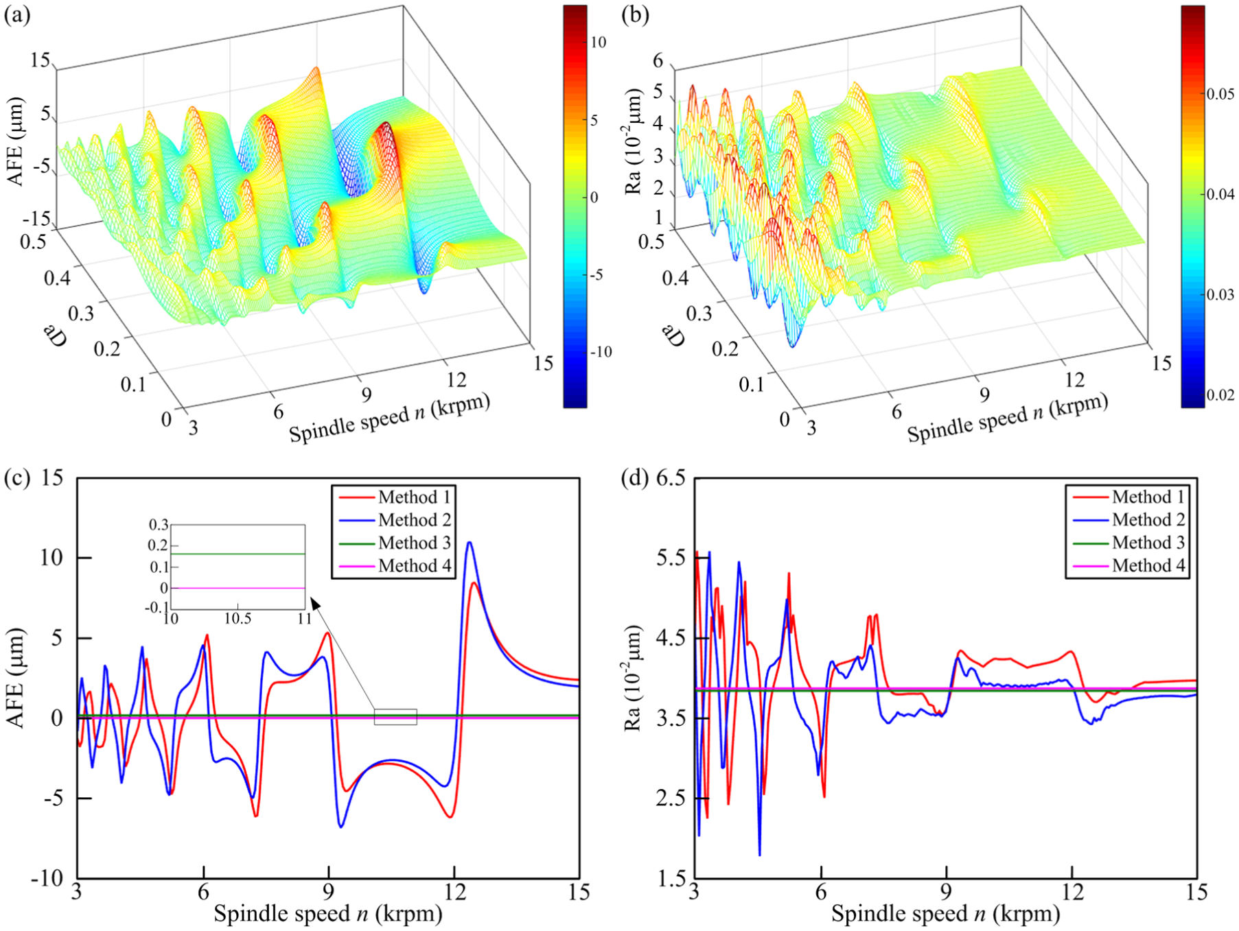
(a) AFE under different n and aD, (b) Ra under different n and aD, (c) AFE under different n with aD = 0.3 and (d) Ra under different n with aD = 0.3.
Furthermore, Figure 7(c) and (d) give out the detailed results of Figure 7(a) and (b) with radial immersion ratio aD = 0.3, respectively. We can see that the AFE and Ra vary evidently with spindle speed. Besides, what should be pointed out is that the extremum is located around some certain spindle speeds, which can easily cause cutter system resonance as a result of harmonic components of milling force. In the single-DOF cutter dynamic system, the natural frequency in the normal feed direction is about 1824 Hz. When the spindle speed is around 12.16, 9.12, 7.29 and 6.08 krpm, the third-, fourth-, fifth- and sixth-order harmonic of tooth passing frequency of milling force is coincident with the natural frequency of the cutter system, respectively. Here, the resonance spindle speed and natural frequency will satisfy
Beyond that, the results of the other three methods are also plotted in the Figure 7(c) and (d). By contrast, the simulated results of method 1 and method 2 have a slight distinction, especially around the resonance and low spindle speed, which indicates that the force–displacement coupling effect has a non-ignored influence on the form error. As the dynamic excitation is neglected, both results of AFE and Ra using method 3 and method 4 are a constant value, in which the AFE of method 4 is equal to zero. The comparison demonstrates that both method 3 and method 4 cannot obtain an accurate simulation results for form error.
The influence of cutter runout on form error
Figure 8(a) and (b) are the simulated results of AFE and Ra under different spindle speeds n and radial immersion ratios aD using method 1 with consideration of cutter runout effect, respectively. The milling parameters are the same with that in section “The influence of spindle speed n and radial immersion ratio aD on form error”, and the cutter runout parameters are
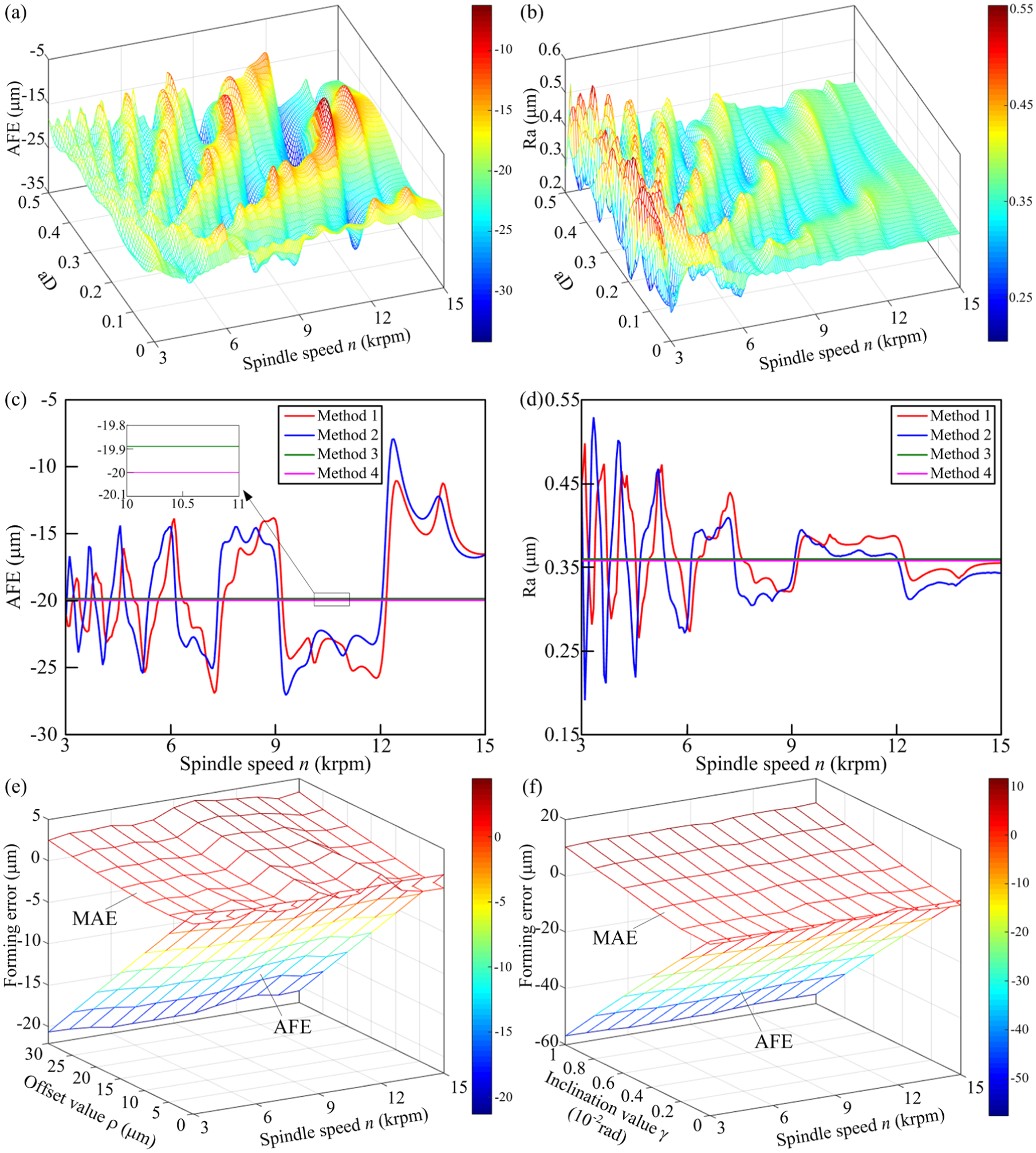
(a) AFE under different n and aD, (b) Ra under different n and aD, (c) AFE under different n with aD = 0.3, (d) Ra under different n with aD = 0.3, (e) AFE and MAE under different offset value and (f) AFE and MAE under different inclination value.
Similarly, Figure 8(c) and (d) further detail the results of Figure 8(a) and (b) with radial immersion ratio aD = 0.3. It seems that the number of local extrema of AFE and Ra increases when comparing with Figure 7(c) and (d). This is because that the cutter runout would cause new harmonic components of milling force, which is equal to the spindle passing frequency and its harmonics, and can also excite the cutter system to produce resonance. Hence, when the resonance spindle speed and natural frequency satisfy
At last, Figure 8(e) and (f) analyze the effect of cutter runout offset value and inclination value on the AFE and MAE, respectively. Here, the axial depth of cut ap is 10 mm, and the radial immersion ratio aD is 0.03. We can see that under the milling condition with a very-low radial immersion ratio, the influence of spindle speed on form error will become weak. Besides, the MAE shows a linear increase with the increase in the cutter runout offset and inclination value, while the AFE shows a linear decrease with the same range of cutter runout parameters, which means the over cut condition will become more and more serious with the increase in the offset and inclination value. In addition, the inclination value is more likely to lead to the increase in the form error than offset value.
The influence of milling type on form error
Figure 9(a) and (b) are the simulated results of AFE and Ra under different milling types using method 1 without cutter runout effect, respectively. The machining parameters during the down milling are axial depth of cut ap = 1 mm and feed per tooth ft = 0.1 mm/tooth. The results show that the AFE and Ra with the same radial immersion ratio aD under different milling types are different. From Figure 9(a), when the radial immersion ratio is equal to 0.3, the amplitude fluctuation ranges of up and down milling are close to each other. But under the radial immersion ratio with 0.05, the amplitude fluctuation range of up milling is far less than that of down milling. The simulated results of Ra shown in Figure 9(b) have the same conclusion. In fact, the manufacturer always applies down milling during the finishing operation, but the study shows that some potential milling conditions in up milling can obtain a higher form precision than down milling, which can provide more options for machining process.
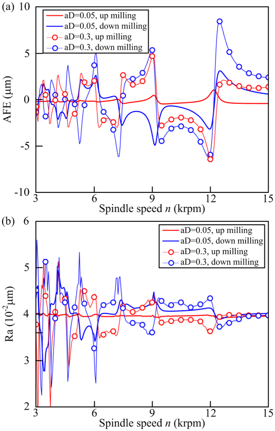
(a) AFE under different milling types and aD and (b) Ra under different milling types and aD.
The influence of damping and stiffness of cutter system on form error
Figure 10 is the simulated results of AFE and Ra under different damping and stiffness of cutter system using method 1 and method 2 without cutter runout effect, respectively. The natural frequency of the system remains unchanged when changing the damping and stiffness. The variable Cp in Figure 10(a) and (b) is the proportion between the simulated damping value and experiment value, and the variable Kp in Figure 10(c) and (d) is the proportion between the simulated stiffness value and experiment value. The experiment value of damping and stiffness are given in Table 1. The machining parameters during the down milling are axial depth of cut ap = 1 mm, radial immersion ratio aD = 0.3 and feed per tooth ft = 0.1 mm/tooth. It can be evidently seen that with the increase in the damping and stiffness, the amplitude fluctuation range of AFE and Ra within the whole spindle speed field shows a decrease trend, especially around the resonance spindle speed, which means that a large damping and stiffness can restrain the cutter vibration amplitude and reduce the dependence of AFE and Ra on spindle speed.
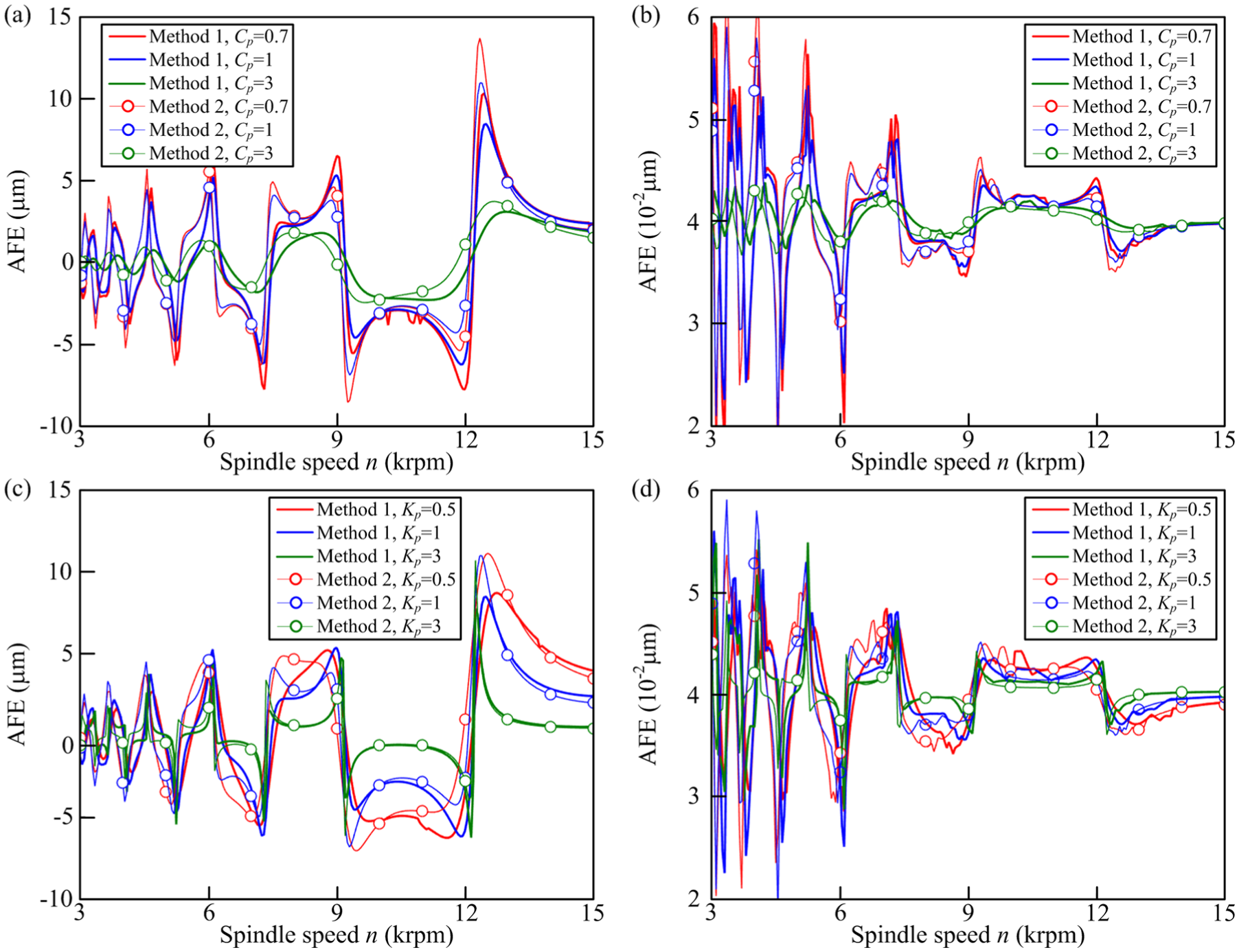
(a) AFE under different damping, (b) Ra under different damping, (c) AFE under different stiffness and (d) Ra under different stiffness.
Besides, from the comparison between method 1 and method 2, we can see that when the damping and stiffness are large, the calculation results of the two methods are close to each other, but when the damping and stiffness are low, the deviation of the two methods become remarkable, especially around the resonance spindle speed. This result means that the force–displacement coupling effect during cutter/workpiece engagement process is strong when the damping and stiffness of the system is low. Hence, for a milling system with low damping and stiffness, we should apply the method 1 to analyze the form error.
The influence of multi-DOF cutter system on form error
Figure 11(a) shows the simulated results of AFE under single-DOF and multi-DOF dynamics model of cutter system using method 1 with cutter runout effect. The machining parameters during the down milling are axial depth of cut ap = 1 mm, radial immersion ratio aD = 0.03 and feed per tooth ft = 0.1 mm/tooth, and the cutter runout is the same with that in Table 2. As multi-DOF model of cutter dynamics model considers the influence of multi-order natural frequencies, the number of resonance spindle speeds will increase compared with the single-DOF model. Besides, the simulated results of AFE by the multi-DOF model under different spindle speeds are closer to the measured ones than the single-DOF model, which means that it is necessary to consider the multi-order modal characteristics of cutter system.
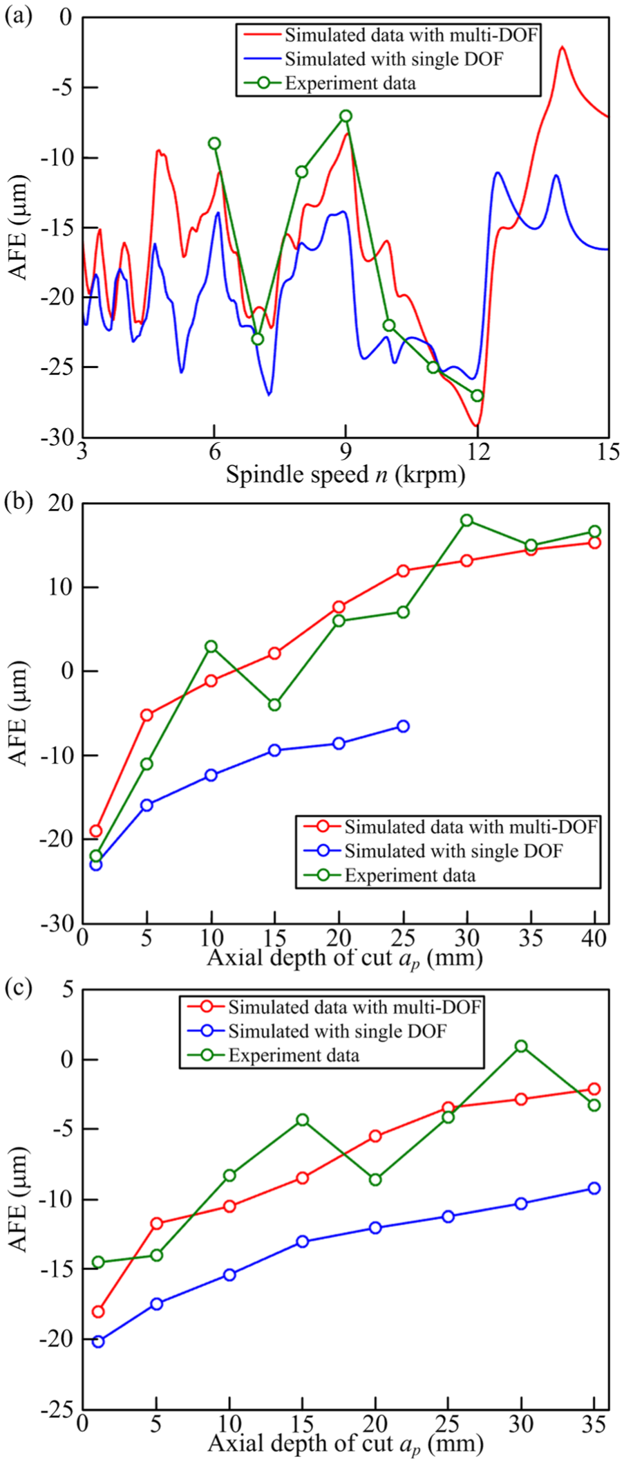
(a) Simulated and measured results of AFE, (b) AFE under different ap with n = 9000 and (c) AFE under different ap with n = 6000.
For further comparing, Figure 11(b) and (c) shows the simulated results of AFE under different axial depth of cut using method 1 with multi-DOF model and single-DOF model within stable milling, respectively, where the measured data are also plotted in the figures. Here, other machining parameters simulated in Figure 11(b) and (c) are the same with that in test 1 and test 2 of Table 2, respectively. It can be seen that the simulated results of the two kinds of models are close when the axial depth of cut is small, but gradually deviate with each other with the increase in the axial depth of cut. Besides, the simulated results show a good agreement with the measured ones. The above study means that the multi-DOF model can describe the cutter/workpiece engagement process more accurate than the single-DOF model, especially under the milling condition with a large axial depth of cut.
Conclusion
This article presents an enhanced time-domain simulation method for cutter/workpiece dynamic engagement process with consideration of the multi-DOF dynamics model of cutter system and cutter runout and further builds up a reconstruction algorithm of machined surface and evaluates the form error. Besides, the study systematically compares the performances between the proposed method and other three kinds of methods, and the study results mean that the proposed method has the best performance in terms of simulation accuracy. The main conclusions of this article are given as follows:
The form error has an obvious dependence characteristic on milling parameters, especially on the spindle speed and radial depth of cut. Around the resonance spindle speed, the form error will change dramatically and lead to multi-extremum, which has been verified by the proposed method and method 2, but method 3 and method 4 cannot describe this kind of variation.
The proposed multi-DOF dynamics model of cutter system can more accurately reflect the actual cutter/workpiece engagement process than the single-DOF model, especially under the milling condition with a large axial depth of cut, where the multi-modal characteristics of cutter system will be prominent.
For a cutter system with a low damping or stiffness, the force–displacement coupling effect during tool/workpiece engagement is strong, and the proposed method can obtain higher calculation accuracy than other methods. While for a cutter system with large damping or stiffness, the method 2 can also achieve an accurate result, which is close to the proposed method.
The existence of cutter runout would not only increase the actual cutting radius, and lead to over cut, but also cause new harmonic components of milling force, then result in the growth of number of resonance spindle speeds. Besides, it would change the tooth cutting state during the start/exit stage, thus seriously deteriorate the surface roughness.
Footnotes
Declaration of conflicting interests
The author(s) declared no potential conflicts of interest with respect to the research, authorship and/or publication of this article.
Funding
The author(s) disclosed receipt of the following financial support for the research, authorship, and/or publication of this article: This work was supported by the National Natural Science Foundation (No. 51675417), the Key Project of National Natural Science Foundation (No. 51235009) and the China Scholarship Council (No. 201606280184).