
Abstract
In micro scale cutting, tooling geometry plays a significant role in determining machining quality and tool life, and the knowledge of tooling geometrical effects on process performance potentially benefits engineers on improving tool designs and selecting optimum cutting conditions. This research aims to comprehensively investigate tooling geometrical effects on the process performance in micro milling using a finite element method supported with well-designed cutting trials. In the study, a benchmark three-dimensional tooling model, incorporating rake angle, relief angle, helix angle, diameter and cutting edge radius is initially developed for simulating the micro milling process under large deformations. The simulation is then experimentally validated and the predicted micro chip formation and cutting forces are in reasonable agreement with measured results in cutting trials. Furthermore, finite element-based simulations are performed under different helix angles, rake angles and cutting edge radius, and comparisons of cutting forces, tool stresses, tool temperatures, chip formation and temperatures are presented and discussed. It is found that the cutting edge radius is the most influential factor on the tool’s process performance, followed by helix angle, and rake angle has less effect.
Introduction
With the continuing trend towards miniaturization, micro milling plays an increasingly important role in fabricating micro parts or components directly and cost-effectively. However, unpredictable tool life and premature tool failures remain major obstacles for application of the technology, and extension of tool life presents a key issue for tool manufacturers and researchers.
For micro tool design, optimum tooling geometry is essential for achieving robust stiffness and mechanical strength, avoiding chip clogging, and therefore, improving tool life and tooling performance. Although dynamic cutting load is considerably low, micro tools easily suffer from deflection, chatter and premature breakages, resulting from dramatically reduced tool rigidity and bending strength. Stress concentration on sharp cutting edges may cause potential brittle fracture, damage part quality and lead to shorter tool life. High temperatures accelerate tool wear development, which increases cutting forces and burr formation, as well as degrades forming accuracy. Also, chip evacuation capability presents a key factor for determining tool life as inappropriate chip flow renders a rise in possible blockages inside tool flutes, resulting in accumulated heat and a high risk of sudden tool failures. Therefore, it is essential and much needed to adopt optimum geometrical features so as to achieve low cutting forces, tool stresses and temperatures, and avoid chip clogging. Furthermore, scientific understanding of tooling geometrical effects of a micro tool on its process performance becomes extremely vital for enhancing the tool life and cutting performance.
Li 1 analysed the effects of structural features on the strength of cutting edges employing a finite element method (FEM) and reported that a negative rake angle, low helix angle and relief angle can significantly reduce the maximum stress level on cutting edge corners, while there is only a slight stress effect caused by alteration of the cutting edge radius. Fang et al. 2 performed an investigation on three types of micro tools in terms of rigidity and cutting performance in order to improve the tool life and quality of machined parts. Based on FEM analysis and experimental study, they concluded that D-type end mills have both higher rigidity and better performance compared with those of typical two-fluted end mills and Δ-type end mills. Fleischer et al. 3 designed and optimized single-edged micro tools based on the structural stability analysis. However, the researches listed above are studied only in a simple manner, i.e. tooling geometrical effects on tool stresses or tool shape influences.
The research presented in this article aims to investigate tooling geometrical effects on the process performance in a comprehensive manner for the purpose of practical tool design and optimization. In the study, a benchmark three-dimension (3D) micro milling simulation is initially carried out and experimentally validated, followed by simulations using tools with different helix angles, rake angles and cutting edge radius. Comparisons of predicted cutting forces, tool stresses and tool temperatures, as well as chip formation and temperatures, are presented and discussed for determining individual influence so as to provide scientific knowledge and understanding for optimizing tool design and improving consequent cutting performance.
Tooling geometry and characterization
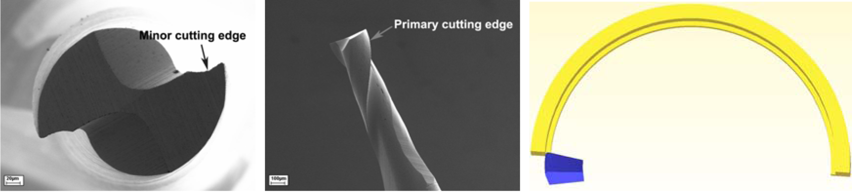
The typical shape and geometry of micro tools are directly scaled down from those of conventional tools owing to the analogous cutting process. Micro tools are commonly seen in end-mill or ball-nosed tips, and micro end mills are considered in this study. The main geometrical features are diameter, flutes, radial rake angle, radial relief angle, helix angle and cutting edge radius, as schematically illustrated in Figure 1. Because the primary cutting edge of a micro end mill is side edge, radial rake angle and relief angle are universally regarded as rake angle and relief angle for the tooling geometry measurement.
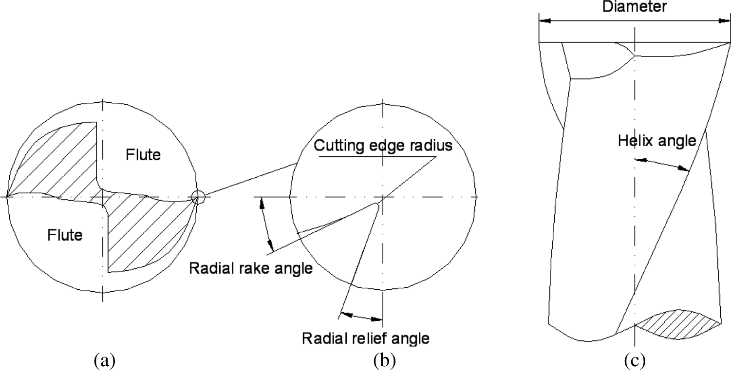
Schematic illustration of a two-fluted micro end mill. (a) Cross section of end mill; (b) zoom in on a cutting edge; (c) side view of end mill.
At present, commercially available micro end mills with Ø25 µm diameter are emerging and smaller sizes down to Ø5 µm are also available by special order (www.pmtnow.com). With a decreasing diameter, the stiffness of tools tends to be weakening dramatically, which can easily cause tool deflection, unpredictable tool life and premature tool failures. Increasing radial rake angle and relief angle, together with reducing cutting edge radius, could lead to sharper but weaker tool tips, which imposes a major limitation on cutting edge strength. Generally, the cutting edge radius for tungsten carbide micro tools are between 0.8∼5 µm owing to restraints of the tool fabricating process. Selection of an appropriate helix angle is crucial for both tool stiffness and chip evacuation, and a 30° helix angle is commonly employed for micro tools design and configurations.
Finite element-based modelling of the micro milling process
Experimentation is a traditional approach for metal cutting research. However, it appears to be costly and, to some extent, inaccessible for studying tooling geometrical effects on the associated process performance. With tiny dimensions and complex configurations of micro tools, there is no experimental method by which stress distribution and tool temperatures on the tips can be measured; in this case, analytical methods tend to be the best solution for accurate estimation of the localized stresses and temperatures acting on the tool near the cutting edges. FEM possesses many potential advantages, such as user-friendly graphical interface, reducing unnecessary cutting trials, shortening lead time, improving cutting tool designs, as well as optimizing process conditions. Furthermore, it is capable of predicting cutting forces, chip flow and a distribution of tool temperatures and stresses under various cutting conditions. Therefore, FEM is chosen for the investigation approach.
A two-dimensional (2D) plane strain model is widely applied for orthogonal cutting process simulations,4–8 and it is also utilized for micro milling force prediction and chip formation analysis.9–11 For a 2D model, helix angle is neglected, which means chips only form and deform in a planar direction, resulting in inaccurate chip flow directions and shapes.
In micro milling, radial depth of the cut for one cutting passage, which corresponds to effective uncut chip thickness, is an important process parameter for determining cutting dynamics or behaviours. In order to identify the difference between 2D and 3D models, the relationship between the uncut chip thickness and other process variables needs to be understood. The schematic diagram of a workpiece in full immersion slot milling is shown in Figure 2.
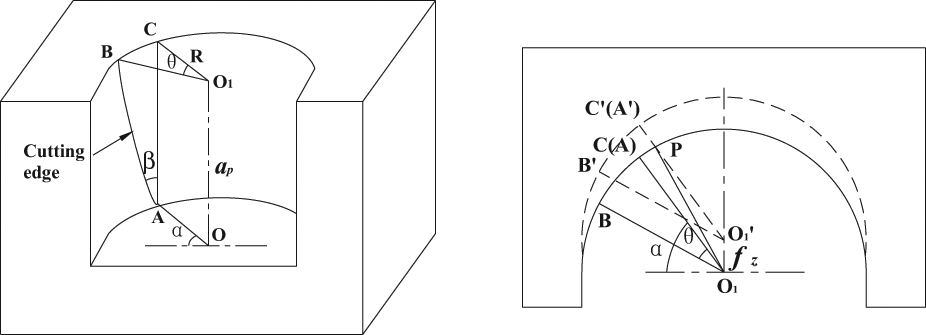
Schematic diagram of a workpiece in full immersion slot milling. (a) 3D view; (b) top view.
According to Figure 2(a), the tool–work contact length and the difference of the rotation angle between bottom and top edge engaging point can be obtained by


where
When the tooth of the cutter advances to the next passage, as shown in Figure 2(b),


where
Substituting equation (2) into (4), the effective uncut chip thickness for B becomes
and the effective uncut chip thickness for every point along cutting edge between A and B can be expressed
where,
For a 2D plane strain model, it is assumed every point on the cutting edge has the same effective uncut chip thickness. While from equation (6), in which the helix angle is taken into account, the uncut chip thickness slightly varies along the tool cutting edge. Additionally, according to equation (1), there is a considerable difference for the cutting edge contact length between 2D and 3D models. Moreover, axial depth of cut is assumed to be equal to the height of the workpiece for 2D models, which is less common for practical operations. Furthermore, in this case, it is impossible to apply bottom boundary conditions as well as a predict axial cutting force component. Based on the above comparison and analysis, it is understood that the plane strain model is relatively inaccurate for representing the practical cutting process, and micro milling simulations should ideally take all structural features, including the helix angle, into consideration for the modelling development.
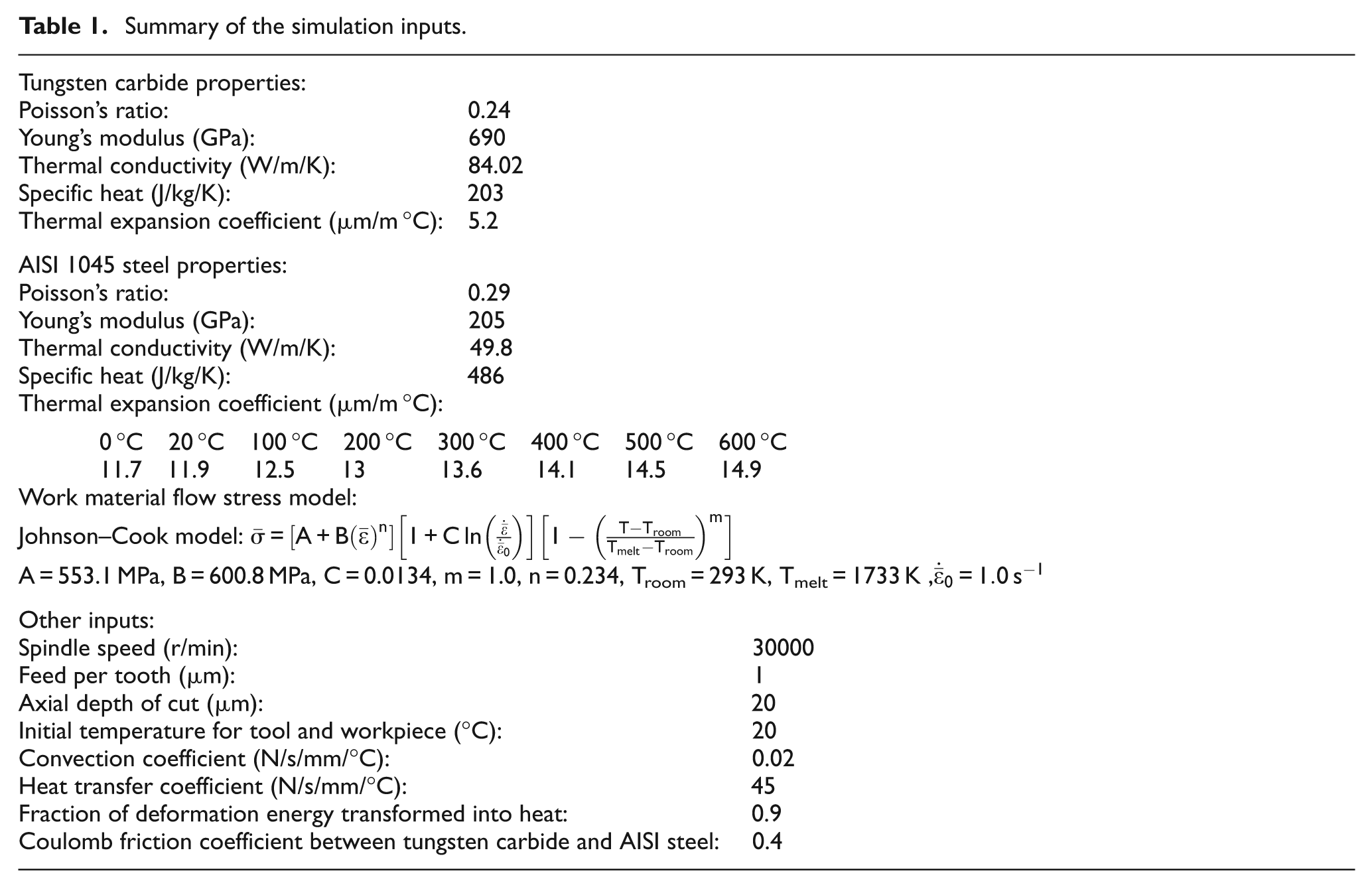
The 3D finite element (FE)-based method proposed by Wu and Cheng 12 is adopted for the process simulations. A benchmark Ø0.3 mm micro end mill with 7° rake angle, 15° relief angle, 30° helix angle and 2.5 µm cutting edge radius, together with the tool and work models are shown in Figure 3. For the tool modelling, only the primary cutting edge on the tool side is considered and the minor cutting edge is neglected. Commercial software DEFORM™-3D is employed for analysing the complex and large deformation process. In the study, the micro cutter is assumed to be rigid, and the workpiece has a homogeneous microstructure and performs plastic deformations. Deformation and heat transfer are calculated in an integrated manner and maximum plastic strain failure criterion is adopted for the chip separation. A Johnson–Cook work material flow stress model and pure sliding friction between the tool and workpiece interface are assumed. The simulation inputs are summarized in Table 1.
Micro end mill and corresponding models. (a) Tool bottom view; (b) tool side view; (c) tool and workpiece models.
Summary of the simulation inputs.
Experimental validation through cutting trials
The simulation is carried out under large deformations without considering the process dynamic influences. Comparisons of the predicted micro chip formation and cutting force components with experimental results are adopted for verifying the simulation results.
Dry slots milling on an AISI 1045 sample is carried on an ultra-precision micro milling machine UltraMill, which is built jointly by UPM Ltd and Brunel University.13–15 The machine has a maximum speed in excess of 200,000 r/min, a radial runout of less than 2 µm and a radial stiffness of 3 N/µm. 16 Cutting forces are recorded by Kistler dynamometer MiniDyn 9256C2 with a four channel charge amplifier 5070A. An A/D data acquisition card 2855A4 is used for transferring signals to a PC and software DynoWare is adopted for analysing and evaluating the cutting forces. The sampling rate in the study is set to be 32,000 Hz, which enables sufficient sampling points in one cutting passage to be recorded. A digital camera is employed for micro tool alignment. Setup of the cutting trials is shown in Figure 4.
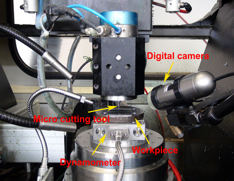
Setup of the cutting trials.
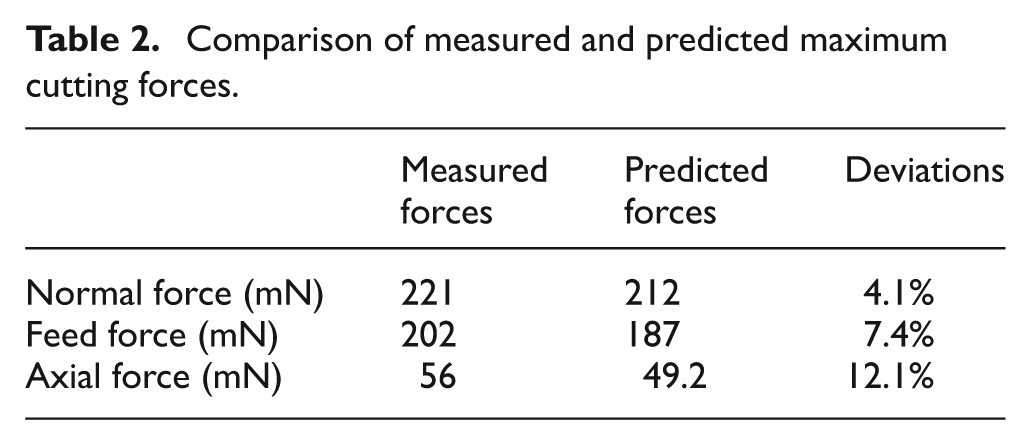
Machined micro chips are collected and observed under a digital microscope Keyence VHX-1000. The predicted spiral-shaped chip is well in agreement with the machined micro chip example (see Figure 5). In addition, averaged cutting forces in five consecutive cutting paths, together with a predicted counterpart, are illustrated in Figure 6, and they are well matched. Furthermore, measured maximum cutting forces in feed, normal and axial directions, together with a predicted counterpart, are compared in Table 2. There is less than 8% deviation for normal and feed forces, and around 12% for axial forces, which demonstrates reasonable accuracy of the simulation results. Based on the above comparison and analysis, it is concluded that the simulation is correct and convincing, and the 3D FE-based method could provide reasonable accuracy for scientific understanding and characterizing the micro milling process, and the proposed model could be regarded as a benchmark model for studying tooling geometrical effects on process performance, including cutting forces, tool stresses, tool temperatures, chip formation and temperatures.
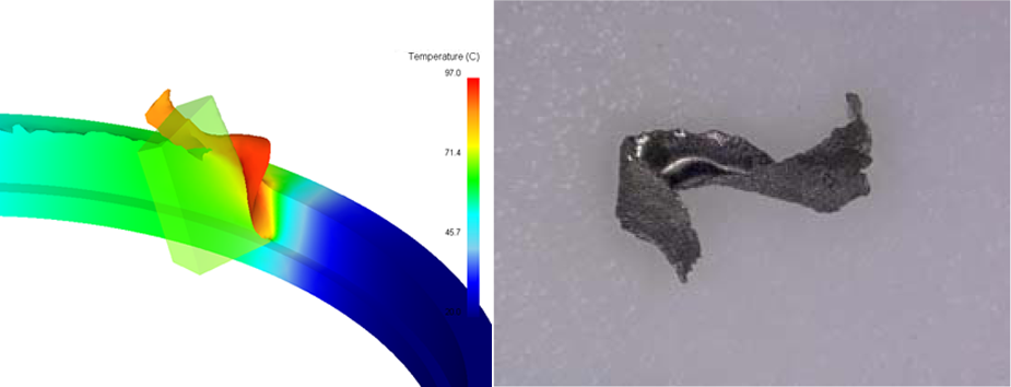
Comparison of predicted chip formation with a chip sample.
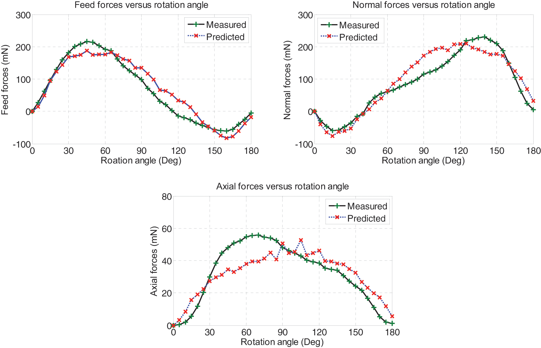
Comparison of cutting forces. (a) Feed forces; (b) normal forces; (c) axial forces.
Comparison of measured and predicted maximum cutting forces.
The effect of tooling geometry on process performance
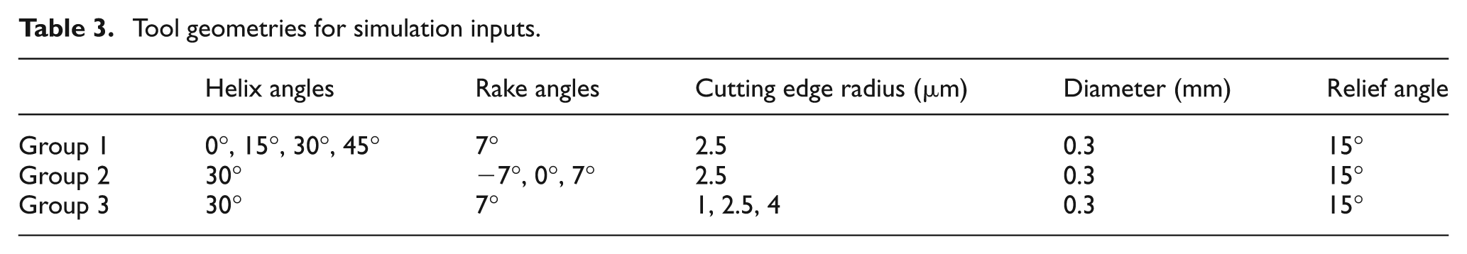
Simulations using different tooling geometries are carried out for understanding respective effects on the process performance. Table 3 shows three geometrical input groups, including group 1 for four helix angle levels, group 2 for three rake angle levels and group 3 for three cutting edge radius levels. For the tool modelling, the pitch height for Ø0.3 mm diameter tools with 15°, 30° and 45° helix angles are 3.5174 mm, 1.6324 mm and 0.9425 mm, respectively. In the same group, when the specified feature changes, the values of the other features remain constant. Variations of tool diameter and relief angle are not considered and the total number of 3D simulations is 8. Predicted cutting forces, tool stresses, tool temperatures, chip formation and temperatures, with respect to different tool geometries, are presented and discussed in the following sub-sections.
Tool geometries for simulation inputs.
Cutting forces
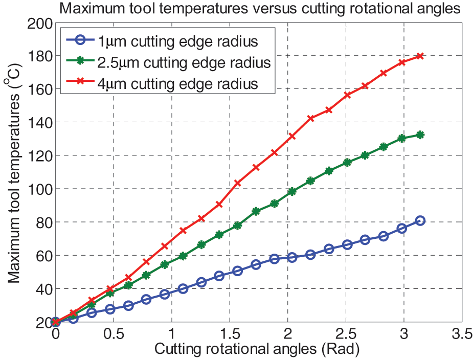
Knowledge of cutting forces in micro milling can be beneficial for improved machining accuracy, a higher production rate and preventing potential tool breakages. 17 Predicted maximum feed forces, normal forces and axial forces using different tooling geometries are shown in Figure 7. First, the effects of the helix angles are tested. Four levels of helix angles are chosen, namely 0°, 15°, 30° and 45°, among which the 30° helix angle is commonly used on commercial micro tools. From Figure 7(a), it is obviously seen that the maximum feed forces and normal forces vary slightly under different helix angles, whereas the maximum axial force increases gradually along with increasing helix angles. Therefore, there is less impact for cutting forces in planar directions by altering the helix angles. From the tool development point of view, no obvious influences in terms of tool deflection are caused by changing helix angles as long as tool stiffness remains constant. Owing to the fact that the cutting edge contact length is higher for high helix angle tools, the cutting force per length unit becomes comparatively lower, which may reduce the possibility of edge fracture.
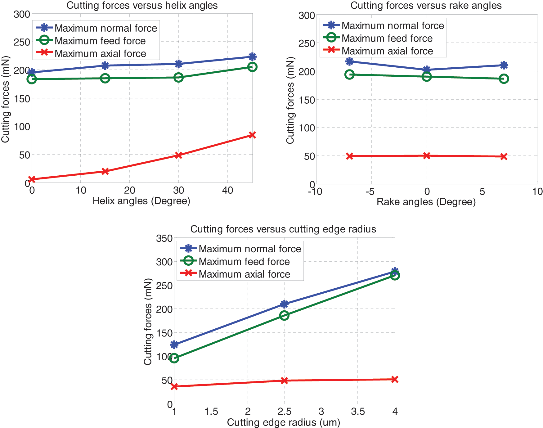
Predicted cutting forces under different tooling geometries. (a) Helix angles; (b) rake angles; (c) cutting edge radius.
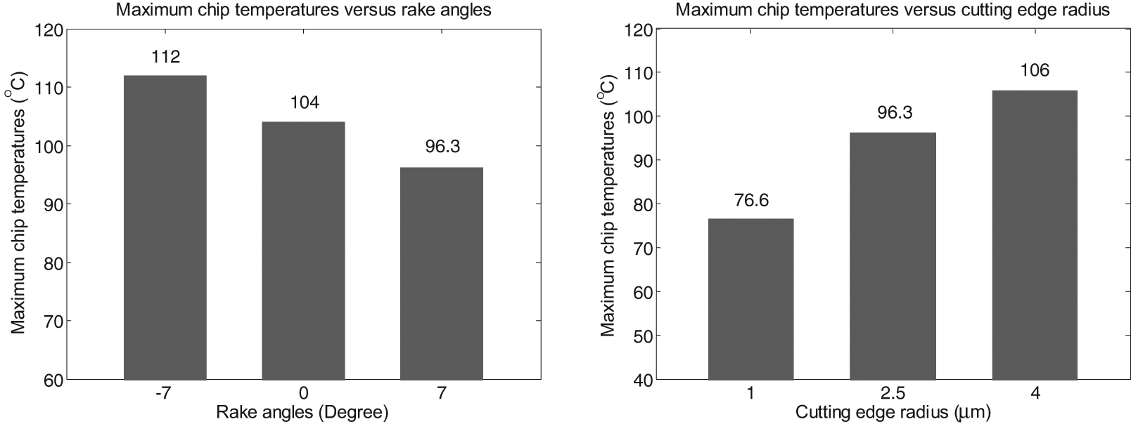
Similar analyses are performed to understand rake angle and cutting edge radius effects on the cutting force components. From Figure 7(b), all the three force components vary rather slightly when rake angle changes from negative to positive, which means less significance for the rake angle impact. And if the cutting edge corner becomes dull, the maximum feed force and normal force rise significantly, whereas maximum axial force almost keeps constant, as depicted in Figure 7(c). According to above results and analysis, it is concluded that the cutting edge radius has the most significant effect on the cutting forces, followed by helix angle, and rake angle has the least impact.
Tool stresses
Figure 8 illustrates the predicted tool stress values under the highest resultant forces during one cutting passage. As seen from Figure 8(a), the rising helix angles from 0° to 45° results in steadily increasing tool stresses. Probably it is mainly owing to weakened cutting edges for high helix angle tools. According to Figure 8(b), rake angle also has considerable effect on the maximum stresses at the cutting edge corner. Among all the three levels, the positive rake angle has the maximum stress and the negative rake angle has the minimum stress. Because the estimated cutting forces for tools with different rake angles vary little (see Figure 7(b)), this phenomenon can be explained by the edge strengthening effects. Therefore, in hard milling or roughing applications, a negative rake angle is more preferable for maintaining good edge strength so as to reduce edge stresses. A sharp cutting edge corner also significantly reduces the level of maximum stresses, as shown in Figure 8(c). Although the tool cutting edge becomes weaker with a smaller edge radius, cutting forces decrease greatly as well (see Figure 7(c)) and offset the cutting edge weakening effects. Therefore, the 1 µm edge radius has the least tool stress, followed by 2.5 µm and 4 µm.
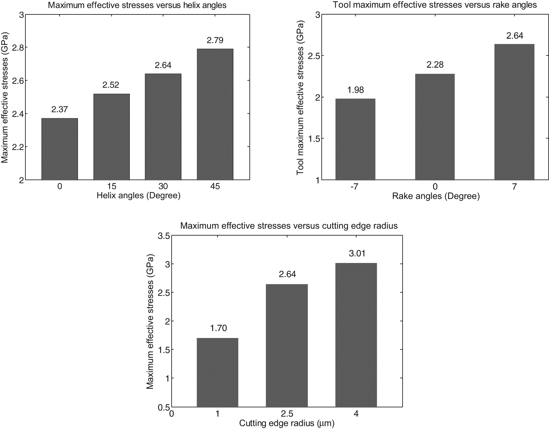
Predicted tool stresses under different tooling geometries. (a) Helix angles; (b) rake angles; (c) cutting edge radius.
Tool temperatures
An understanding of the tool temperature distribution gives possible guidance for more rational tool designs and leads to an improved tool life. Figure 9 shows predicted maximum temperatures on the primary cutting edges of tools employing different helix angles during one cutting passage. It is clearly seen that tools with higher helix angles are more likely to accumulate more heat on the tips, which may be explained by a concentrated and reduced tool–chip contact area. From Figure 10, it can be seen that the high temperature zones tend to decline from the tool–work interface line to the cutting tip areas, along with increasing helix angles.
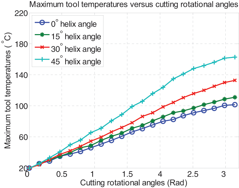
Predicted tool temperatures under different helix angles.
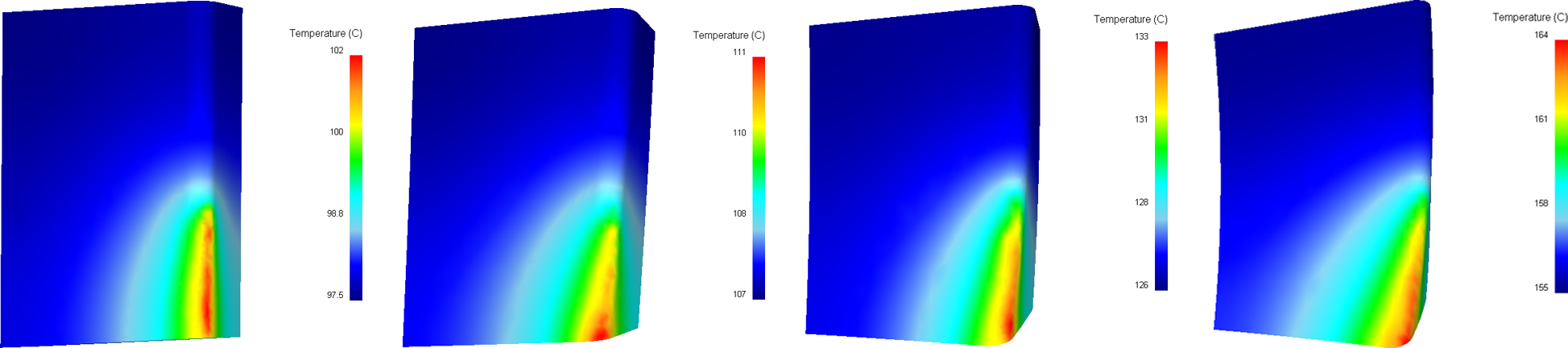
Tool temperature distribution under different helix angles after one cutting passage. (a) 0°; (b) 15°; (c) 30°; (d) 45°.
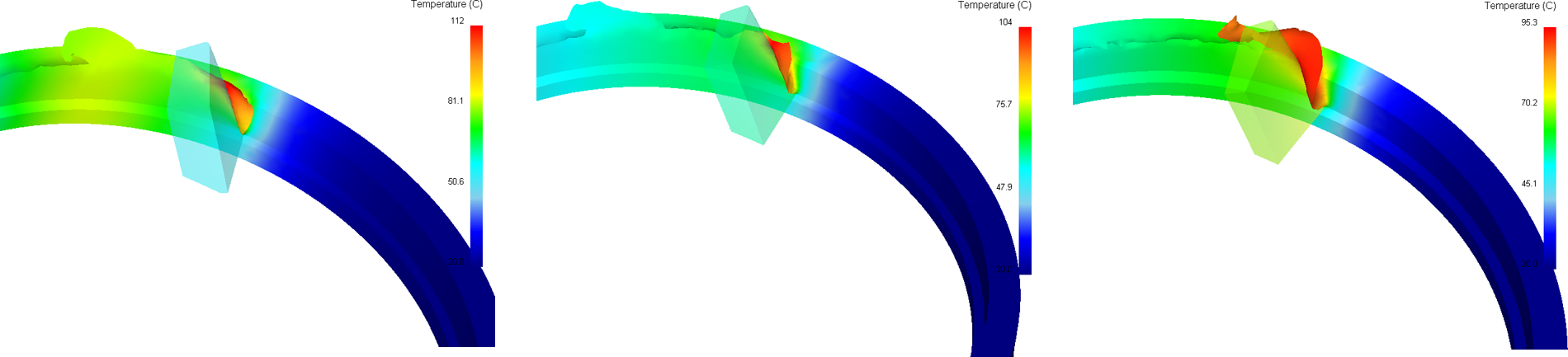
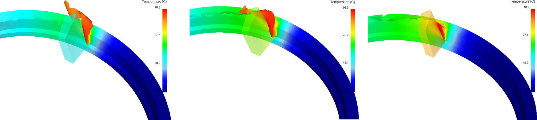
From Figures 11 and 12, it is clear that tool temperatures are also influenced by rake angles; a negative rake angle has less impact on maximum tool temperature and a positive rake angle has the most effect. A smaller cutting edge radius greatly reduces the level of heat generation, as evident in Figures 13 and 14, and compared with the helix angle and rake angle; the cutting edge radius has the most significant effect on the tool temperatures.
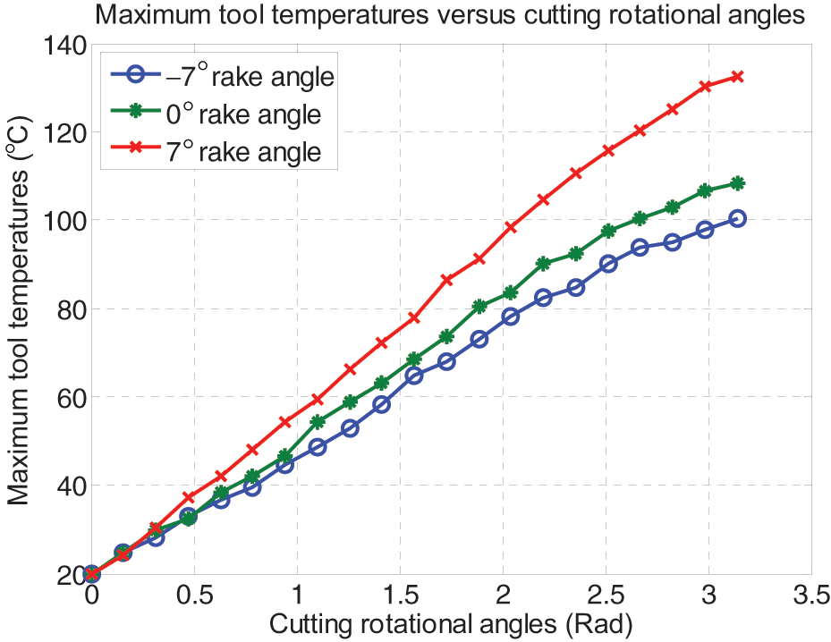
Predicted tool temperatures under different rake angles.
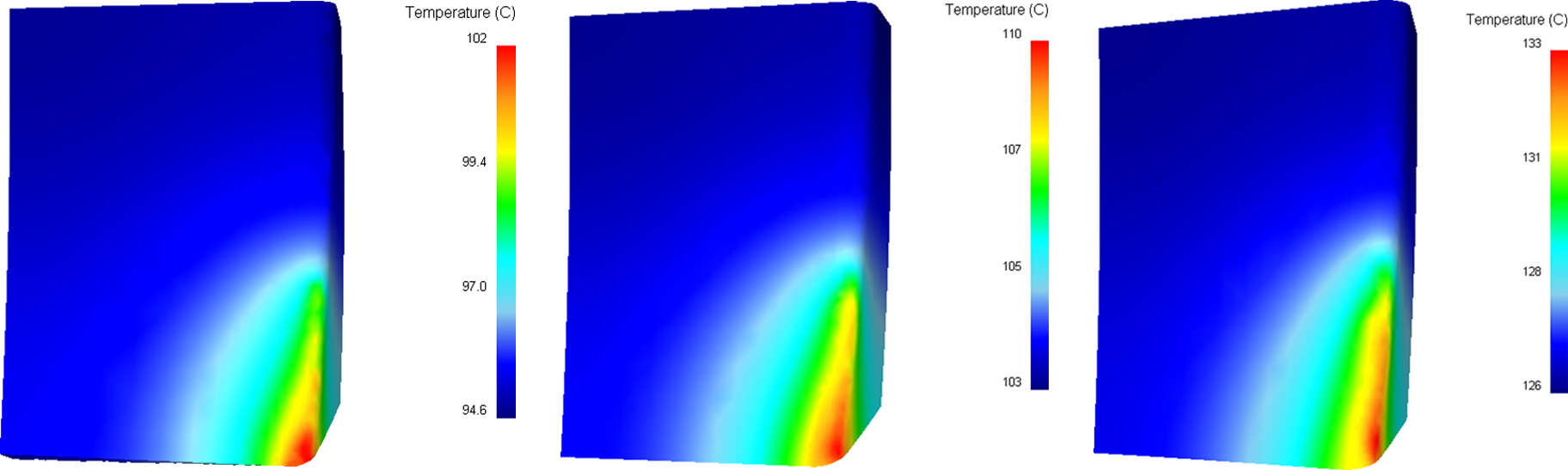
Tool temperature distribution under different rake angles after one cutting passage. (a) −7°; (b) 0°; (c) 7°.
Predicted tool temperatures under different cutting edge radius.
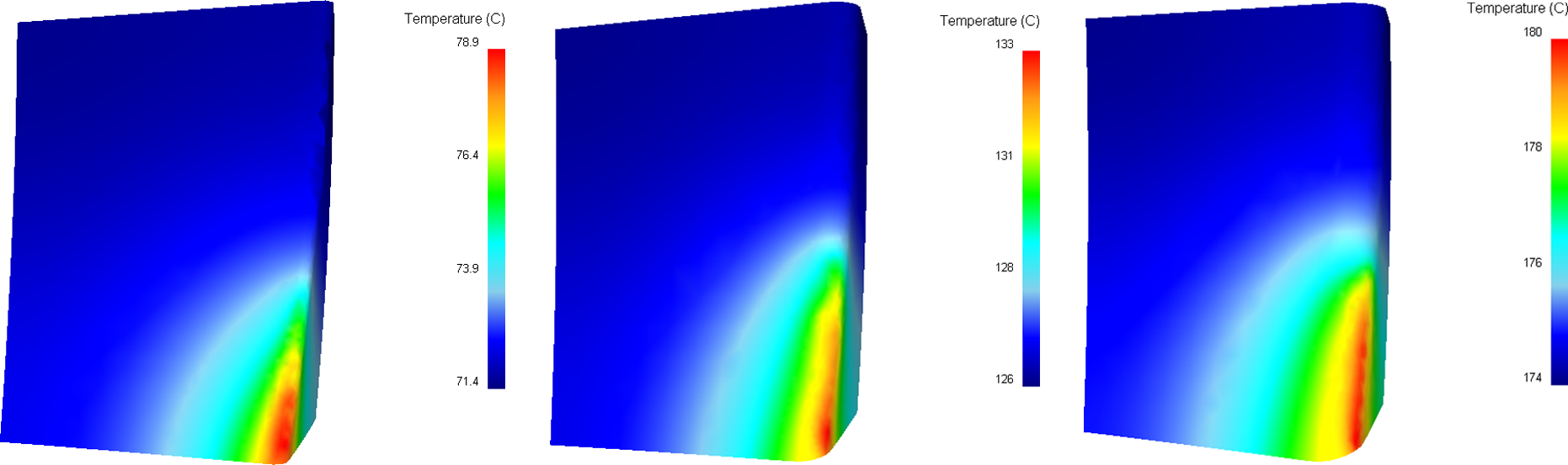
Tool temperature distribution under different cutting edge radius after one cutting passage. (a) 1 μm; (b) 2.5 μm; (c) 4 μm.
Since the temperature distribution imposes a major impact on the tool wear development, resulting in a significant wear rate on high temperature zones, the cutting edge, particularly for tip points, may easily become worn and blunter. Therefore, major wear for a two-fluted end mill is mainly concentrated on two cutting tip points. To this point, for the sake of reducing the tool temperature so as to reduce tool wear and extend tool life, a high helix angle, positive rake angle and dull cutting edge may not suitable for high-duty operations.
Chip formation and temperatures
Chip formation refers to chip flow directions, shapes and minimum chip thickness, and minimum chip thickness in micro milling is regarded as the smallest radial uncut chip thickness when a chip can be formed. Owing to the intermittent cutting mechanism and self-breaking capability in micro milling, helical and low temperature chips become more desirable for a better surface finish, longer tool life and less energy consumption.
After a half pass (90°) milling, the maximum radial depth of cut, which is approximately equal to feed per tooth, has been reached. Chips tend to be different in flow directions and shapes using various tools, as shown in Figure 15. Resulting from the applied boundary constraints on the bottom plane, the chip flows both horizontally and vertically with a straight cutting edge tool (see Figure 15(a)), which reflects the inaccuracy of the chip formation prediction by plane strain models. 10 According to the comparison of chip flow directions under different helix angles, it is certain that the fluent chip ejection can benefit from a higher helix angle and also, in this circumstance, there is less opportunity for chips to interact with the tool rake surface, which may reduce the possibility of crater wear. However, for 45° helix angle tools, there are almost no chips produced and burrs can only be formed at the edge of workpiece as a result of plastic deformation, which is obviously demonstrated in Figure 15(d). Because of the worn cutting edge and increasing axial cutting force for 45° cutters, a large plastic deformation of the work material takes place in the axial direction. The existence of burrs may cause significant fluctuations of the cutting forces for the subsequent cutting passages, and makes tool wear and life unpredictable. For 30° helix angle tools, burrs appear much less, and complete spiral chips are also formed. As a result, this type of tool not only possesses good chip evacuation capability but also improves machining stability. In addition, the predicted maximum chip temperatures, using four types of tools as shown in Figure 15(e), are 104 °C, 101 °C, 96.3 °C, 97.2 °C, respectively, and 30° high helix angle tools generate the lowest chip heat, which may be owing to reduced contact between the tools and work material compared with 0° and 15° tools, and less plastic deformation compared with 45° tools. From the standpoint of energy saving, a 30° helix angle is more suitable for micro tool designs.
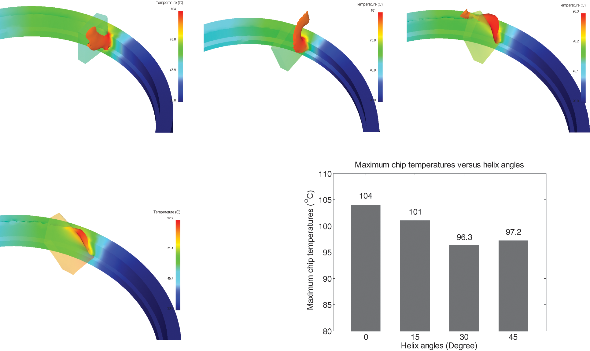
Predicted chip formation and temperatures after a half cutting pass under different helix angles. (a) 0°; (b) 15° (c) 30° (d) 45° (e) maximum chip temperatures under different helix angles.
According to Figures 16 and 17(a), it is obvious that a positive rake angle facilitates chip formation and evacuation, as well as less heat generation. When the tool rake angle becomes more negative, compressing rather than shearing is dominated in material removal and chips can hardly be formed.
Predicted chip formation after a half cutting pass under different rake angles. (a) −7°; (b) 0°; (c) 7°.
Maximum chip temperatures after a half cutting pass under different tooling geometries. (a) Rake angles; (b) cutting edge radius.
The cutting edge radius has a significant impact on chip formation and ejection. Continuous spiral-shaped and low-temperature chips are achieved by small edge corner tools, as illustrated in Figures 17(b) and 18. From Figure 18(c), when using a 4 µm cutting edge radius tool, only a ploughing phenomenon is observed, and there are almost no chips formed owing to a minimum chip thickness effect in micro-scale cutting. Therefore, according to Figure 18(b) and (c), it is certain that the ratio of minimum chip thickness to the cutting edge radius for AISI 1045 steel under the specific cutting conditions, is between 25% and 40%.
Predicted chip formation after a half cutting pass under different cutting edge radius. (a) 1 μm; (b) 2.5 μm; (c) 4 μm.
Based on the above analysis, it is concluded that all, helix angle, rake angle and cutting edge radius, can affect chip formation and temperatures significantly. Different tool geometries have a different response on the chip flow directions, shapes, as well as the minimum chip thickness. To achieve better chip evacuation capability and machining stability, as well as low heat generation, a 30° helix angle, positive rake angle and sharp cutting edge can be more preferable for the specific investigation.
Conclusions
In this study, a comprehensive investigation on tooling geometrical effects in the micro milling process is conducted by a 3D FE-based method supported by well-designed cutting trials. Cutting forces, tool stresses, tool temperatures, chip formation and temperatures of cutting AISI 1045 steel with respect to different helix angles, rake angles and cutting edge radius are predicted, compared and discussed to identify individual geometrical effects. Based on experimental validation and simulation results, the following conclusions can be drawn.
The 3D FE-based approach is capable of characterizing the micro milling process with reasonable accuracy, and it can be employed as a benchmark simulation for studying tooling geometrical effects on the associated process performance.
The cutting edge radius has the most significant effect on cutting forces, followed by helix angle and rake angle.
Rising helix angles increases tool stresses steadily. Compared with the negative rake angle, the positive rake angle has more impact on the tool stresses. A sharp cutting edge can reduce the level of tool stresses considerably.
A higher helix angle, positive rake angle and dull cutting edge lead to higher tool temperatures. Compared with the helix angle and rake angle, the cutting edge radius mostly affects the tool temperature.
The helix angle, rake angle and cutting edge radius affect the chip directions, shapes and minimum chip thickness, as well as chip temperatures significantly. A 30° helix angle, positive rake angle and sharp cutting edge are more preferable for the better chip removal capability, machining stability and less power consumption.
According to above conclusions, the cutting edge radius is the most influential factor for determining the process performance, followed by the helix angle, and the rake angle has the least impact. By taking comprehensive account of the effects of tooling geometries on cutting forces, tool stresses, tool temperatures, chip formation and temperatures, it is suggested that in high-duty micro milling operations, such as cutting hard materials, a low helix angle and negative rake angle can yield better results as a result of maintaining edge strength and enhancing tool life. Whereas, in light or finish cutting, a 30° helix angle, positive rake angle and sharp edge corner are more practical for improving the process performance.
With the decrease in tool diameter, the fabrication of micro tools presents a great challenge owing to a reduction in tool rigidity and the tighter tolerance requirement for tooling geometry. Future efforts will be undertaken towards developing bespoke micro tools with different helix angles, rake angles and cutting edge radius by appropriate grinding technology so as to experimentally investigate and further validate the corresponding cutting performance of the tools.
Footnotes
Appendix
Acknowledgements
The authors gratefully acknowledge Kistler UK Ltd for the dynamometer kit support.
Funding
This research received funding from the UK Technology Strategy Board (TSB) (Grant contract number: BD266E).