
Abstract
Copper clad polyimide is becoming a significant raw material for the manufacturing of special circuits such as antennas. Micro-milling, which provides a direct and flexible fabrication method in three-dimensional product machining, has replaced traditional processing methods such as photolithography. However, severe burr problem which leads to serious power loss due to the skin effect is encountered because of the selection of improper machining strategies and parameters. In this study, the influence of machining strategy on burr formation is investigated at first. Then, the formation mechanism for different kinds of burrs in micro-milling of copper clad polyimide is analyzed. Furthermore, the burr height prediction model is established, and the optimized processing parameters are obtained through response surface methodology, the predicted burr height is 12 µm. At last, a verification experiment is conducted with the optimized processing parameters. The machining result shows that the optimized parameter combination contains spindle speed of 36,110 r/min, feed per tooth of 0.70 µm/z and tool diameter of 200 µm. The average burr height for verification test is 13.9 µm. Because of the instability of copper layer on copper clad polyimide, the actual burr height is slightly larger than theoretical prediction. The error between predicted value and experiment value is 15.8%. What is noticeable is that before optimization, the burr height is up to 100 µm, while after optimization, it reduces to 13.9 µm which is reduced by 86.1%. The achievements in this study are of great significance for optimizing machining parameters and improving machining quality and efficiency of copper clad polyimide, especially in antennas field.
Introduction
Polyimide (PI) is widely used in industry areas especially for the aerospace and aviation fields because of the superiorities such as long-term usage under harsh temperature condition, good insulation property and low dielectric loss. Copper is a commonly used material because of good conductivity and corrosion resistance property. By plating copper on the surface of PI substrate, a brand new material which is defined as copper clad polyimide (CCPI) becomes an excellent raw material for manufacturing special three-dimensional (3D) circuits and parts. 1 While because of the limited plating adhesion force, copper layer is easy to be peeled off from PI substrate among machining process, hence to select an appropriate machining strategy and a group of suitable machining parameters are of great importance.
For machining CCPI, many strategies are used before. Photolithography method is regarded as the proved technique for removing specific areas of copper layer on CCPI. However, it can only be utilized for planar parts, which restricts the processing of 3D parts severely. 2 Laser processing technology shows more advantages compared with photolithography method, while the circuit size processing by laser is limited because of the existence of heat-affected zone. 3 A five-axis computer numerical control (CNC) milling has advantages of high precision, high efficiency, and the capability of 3D parts machining.4,5 Nevertheless, the large tool diameter of traditional milling makes the processing unable to be completed due to the small size of circuit. Therefore, an innovative machining method is urgently needed.
Micro-milling method is taken as one of the most promising methods for removing copper coating from PI substrate,6,7 which shows several advantages such as high material removal rate, the convenience for using, the ability for processing 3D parts, 8 the low machining cost, and the unrestricted processing materials.9–12 However, the milling force brings about several problems13,14 and what affects processing quality most is the burr problem which not only brings about the circuit power dissipation due to the skin effect but also causes short circuit or other fatal problems. The generating mechanism and the solving means for burr in micro-milling were studied by numerous academics and research institutions.15–18 Most of them were focused on the single homogeneous material. Piquard et al. 19 studied the burr formation and phase transformation of NiTi biomedical alloys. Kuan-Ming and Shih-Yen 20 studied the experimental evaluation of the minimum quantity lubrication in near micro-milling of SKD61. Chen et al. 21 and Thepsonthi and Özel 22 established burr formation model for Ti-6Al-4V. Schueler et al. 23 studied burr formation and surface characteristic of titanium alloys. However, the research on removing thin copper layer plated on soft materials like CCPI by micro-milling method is seldom mentioned. Compared with single homogeneous materials, CCPI has a poor machinability because of the limitation of plating adhesion force between copper layer and PI substrate. Hence, improper milling parameters may lead to the copper layer peel off from PI substrate. Moreover, as copper and PI are both highly malleable materials, large deformation of these materials will be caused by the milling force which makes the chip hard to be swept away. Therefore, many factors that can be ignored in machining commonly used materials play an important role in micro-milling of CCPI,24,25 which makes it more difficult for realizing good quality processing.
Based on the above analysis, the purpose of this study is to find appropriate machining parameters for micro-milling of CCPI. In addition, the effect of tool path trajectory is also investigated. After that, a burr height prediction model is established by RSM based on experimental results. Meanwhile, the optimized combination of machining parameters can be obtained. At last, a verification experiment is carried out for proving the effectiveness of optimization result. This research is of great significance for optimizing machining parameters and improving machining quality and efficiency of CCPI, and it provides guidance for machining CCPI in the industrial field.
Material properties of CCPI
The experimental material in this study is defined as CCPI. The substrate is a PI plate whose thickness is 3 mm. Thin copper layer is plated on the surface of PI substrate by magnetron sputtering method at first with the operating temperature below 50 °C. At this time, the thickness of coating layer is only 1 µm. Then, the copper coating layer is thickened to 10 µm on the basis of electroplating technology. By this method, the binding force can be much larger than merely using electroplating technology which guarantees a better machining quality. Pull-off test is conducted using 3M adhesive tape (specification 610), and the test result shows that the adhesion between copper layer and PI substrate can satisfy the requirement of electronics industry. The properties of PI and copper are shown in Table 1. It can be seen that the electrical resistivity is large for PI which makes it a good insulating material, while it is small for copper which makes it a perfect conducting material. The combination of them provides a terrific material for machining special electric circuit such as antennas. However, the elongation and the modulus of elasticity for PI and copper are quite different which make the copper layer more easily to be peeled off from PI substrate among the machining process. In addition, the heat conductivity coefficient for PI is small; hence, a large amount of heat will be generated in machining process. The heat will lead to softening of PI and results in deformation problem which brings about a poor machining quality of circuit pattern edge. From the above analysis, the machining for CCPI is quite difficult compared with traditional materials. It is of vital importance to select appropriate machining strategies and machining parameters for obtaining good machining quality.
Properties of PI and copper.
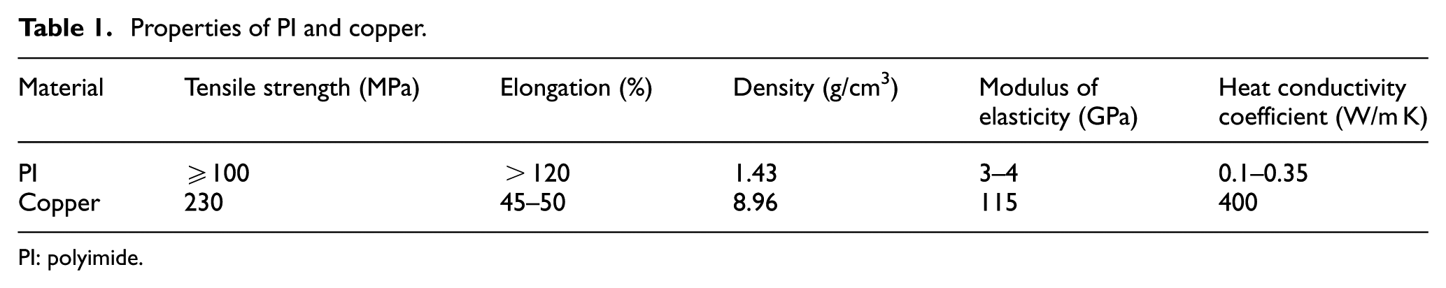
PI: polyimide.
Mechanism analysis for burr formation in micro-milling of CCPI
In order to find appropriate method for machining CCPI with high quality, the burr formation mechanism needs to be investigated first for a deeper understanding. When choosing appropriate cutting parameter combination, the micro-tool can cut off copper layer smoothly; hence, only small size burr or even no burr exists which leads to a good machining quality. However, once the micro-tool fail to cut off copper layer from CCPI because of quite small or large cutting amount, the copper layer will be pushed away because of the feed motion of micro-tool. When the force reaches up to the tensile strength of copper layer and the binding force between PI substrate and metal coating, it will crack. Since the ductility of copper is good, the burr will stay at the edge of machining pattern. At this condition, the burr size is large. Some other factors also affect burr formation in micro-milling of CCPI. (1) The helix angle of micro-milling cutter leads to an oblique cutting process. The component force that is perpendicular to the copper layer is obtained by this angle which makes the copper layer more easily to be peeled off from the PI substrate. Since there is no other constraining force, the protruding copper layer is hard to be cut off and will be pushed to the unprocessed surface, thereby the large burr emerges. (2) Both copper and PI have good ductility and low stiffness; hence, deformation will exist among machining. However, the different deformation degrees make copper layer more easily to be peeled off from the PI substrate and thereby leads to a poor machining quality.
Experimental setup
This research is conducted by setting up a series of experiments. Before experiment, the following equipments are needed to be built.
Machine tool
A five-axis numerical control (NC) machine tool with three linear axes and a tilting rotary table is established, as shown in Figure 1. The spindle speed ranges from 30,000 to 60,000 r/min. The SINUMERIK 840D sl programmed by SIEMENS is applied to control the CNC system.
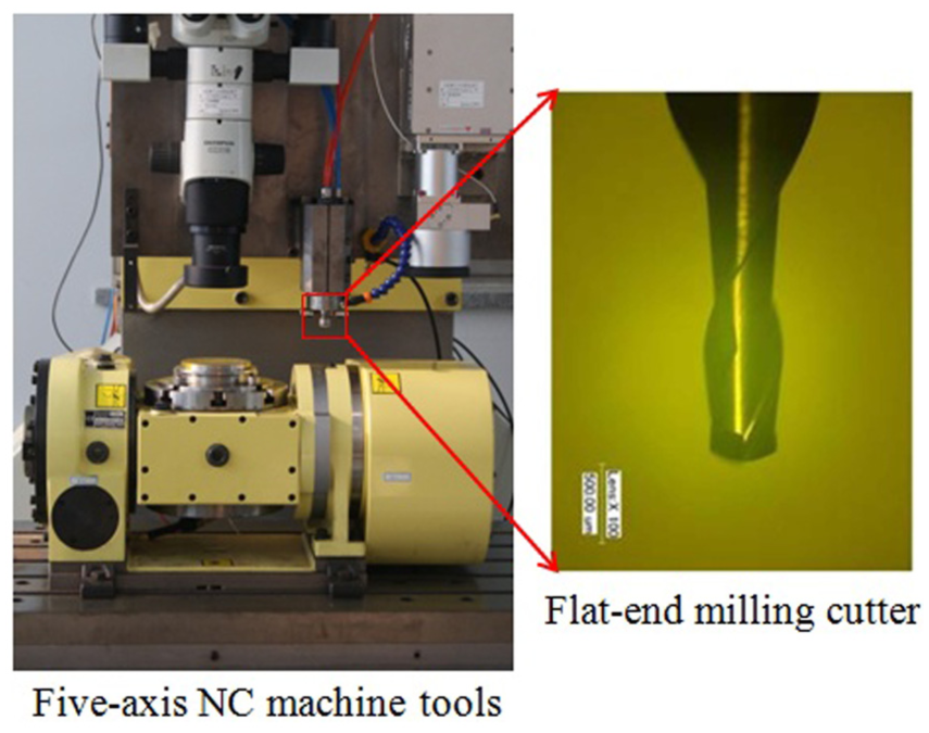
Micro-milling setup.
Micro-milling tool
In this study, the MUGEN coating flat-end mills with two flutes made by NS Corporate is applied. Here, the MUGEN coating means TiAlN-based coating. With both abrasion resistance and lubricity, it makes for long-lasting tools. The helix angle is 30°, and the code is MX TOOL NS230, as shown in Figure 1. In order to meet the minimum pattern size of the circuit diagram, the selected tool diameter must be <600 µm.
Observation and measurement device
A VHX-600E ultra-depth of field 3D digital microscope system produced by KEYENCE Corporation is used for observation and measurement. In this system, a 1/1.8-in charge-coupled device (CCD) is adopted, the maximum pixel number is 54 million and the amplification factor is between 100 and 5000.
Measuring principle
The burr height is calculated by the average burr height at six different positions, and these six positions are fixed for different processing conditions, as shown in Figure 2. They are the tangency points of the horizontal lines and the perpendicular lines with the machined helix line. If there are many burrs at one position, choose the highest one for calculation.
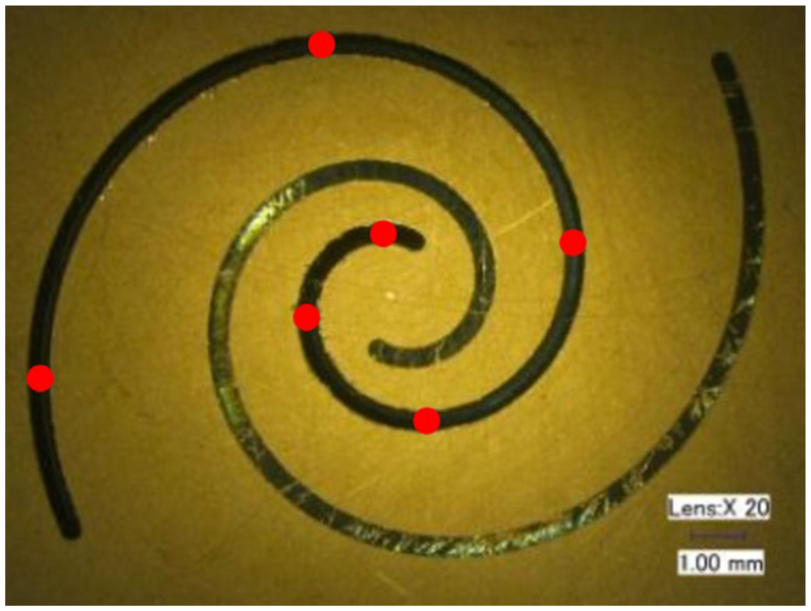
Measurement position for the helix line.
Experimental procedure
Based on the above analysis, machining parameters influence a lot on machining quality and efficiency. Improper machining parameters bring about poor machining quality, and what is worse, it may result in the breakage of micro-milling cutter. Consequently, a large amount of experiments need to be conducted for finding appropriate machining parameters in micro-milling of CCPI. Different processing parameters and tool path strategies are analyzed by single-groove milling experiments of CCPI. The burr height of each sample is observed and measured by the digital microscope. Average burr height is obtained by three repeated tests for each group of parameters. The details of experiments are explained in the following.
Effect of milling depth
To analyze the effect of milling depth on burr height, the processing parameters are selected as shown in Table 2 (no. 1). The experimental results are shown in Figure 3. It can be seen that when milling depth is small, the burr size is quite large. It is because when milling depth is shallow, the milling system composed by micro-milling cutter and workpiece is poor in rigidity.26,27 Consequently, the large burrs are generated because of the spindle run-out and the vibration of cutting tool. With the increasing milling depth, the length of micro-milling tool embedded in the workpiece increases. Meanwhile, the length of overhanging is getting shorter, which attenuates the vibration of cutting tool and thereby makes the burr height smaller. The burr height is not changing much when the milling depth is between 40 and 220 µm. On condition that the milling depth is too large (>230 µm), the removed substrate material will be changed from powder form to ribbon form because of the cutting heat. In this case, the micro-tool is more easily to be wrapped by the ribbon, resulting in a poor boundary quality of the part. Hence, when the milling depth is selected among the normal range, there will be little influence on burr height.
Experimental processing parameters.
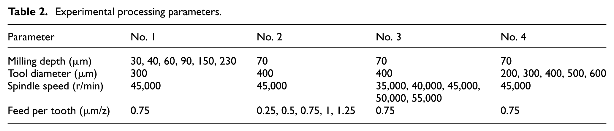
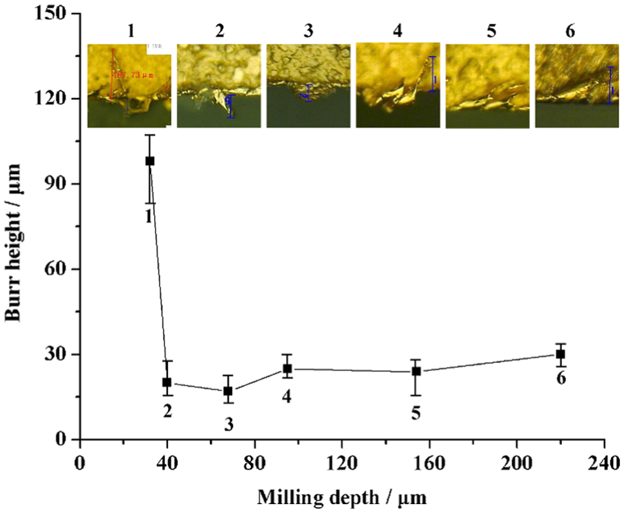
Variation of burr height with the milling depth.
Effect of feed per tooth
To analyze the effect of feed per tooth on burr height, processing parameters are selected as shown in Table 2 (no. 2). Experimental results are shown in Figure 4. It can be found that when feed per tooth is below 0.5 µm/z, the burr height has an increasing tendency and then decrease until 0.75 µm/z, after that, the burr height increases sharply with the increasing feed per tooth. The reason is that even though the edge radius is quite small, it still influences machining quality because of the small feed per tooth. When the feed per tooth is much smaller than the tool cutting edge radius, there is no chip produced, the copper layer is pushed away instead of cutting off, and the burr size has an increasing tendency. When the feed per tooth becomes larger than the tool cutting edge radius, the copper layer is removed by cutting off; hence, the burr height becomes smaller than before. However, with the cutting amount of each flute getting larger, the amount of cutting by each flute is increased, which leads to part of the copper coating tear off instead of cutting off because of the material property. Therefore, the burr height becomes larger accordingly.
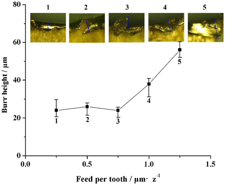
Variation of burr height with the feed per tooth.
Effect of spindle speed
To analyze the influence of the spindle speed on burr height, processing parameters are selected as shown in Table 2 (no. 3). Experimental results are shown in Figure 5. The result shows an approximately linear relationship between burr height and the spindle speed. With the increasing spindle speed, the burr height increases synchronously. What is noticeable is that the diameter of tool is 400 µm, while the width of groove is >400 µm which indicates that the run-out exists in high-speed milling process. Hence, the main reason for the variation tendency of burr height is that the high spindle speed leads to a drastic run-out of micro-milling cutter which makes the machining process unstable. Consequently, the overall tendency of burr height increases with the increasing spindle speed.
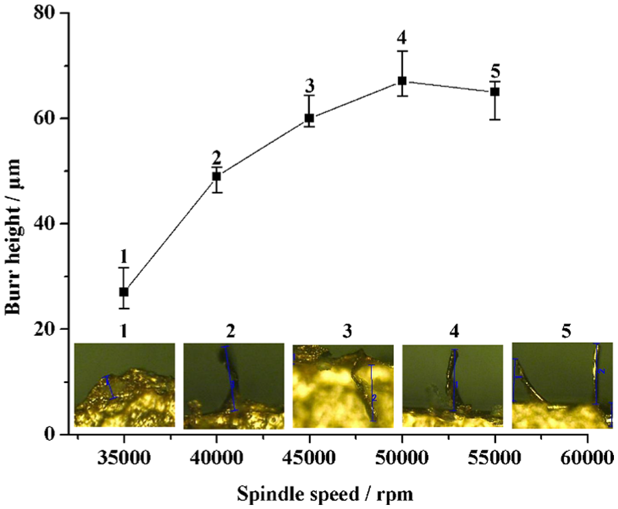
Variation of burr height with the spindle speed.
Effect of tool diameter
In macro-scale fabricating process, the tool diameter can be ignored, while it becomes a significant factor in micro-milling due to the tiny cutting amount. Therefore, the effect of tool diameter on burr height is needed to be explored. The processing parameters are shown in Table 2 (no. 4), and experimental results are shown in Figure 6. The result shows that when the tool diameter is <400 µm, burr height is increased with the increasing tool diameter. After that, the burr height remains constant. It is because when the tool diameter is small, the cutting amount is relatively small which leads to a small milling force. The workpiece is composed of two materials with a limited binding force; hence, when the milling force is smaller than the binding force, the burr height will be increased with the increasing cutting amount. However, when the milling force becomes larger than the binding force because of the increasing tool diameter, the copper layer will be peeled off instead of cutting off; thus, the burr height remains at a higher level.
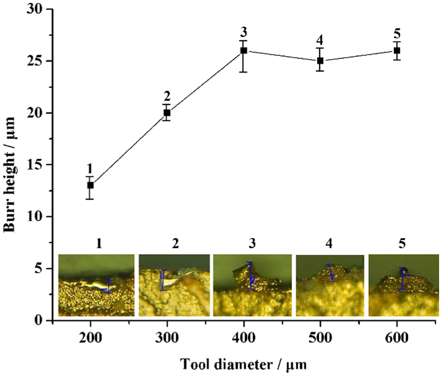
Variation of burr height with the tool diameter.
Effect of tool path curvature
To analyze the influence of tool path curvature on burr height, the concentric circles with different radii are machined in this study, and the processing parameters are selected as shown in Table 3 (no. 1). The experimental results are shown in Figure 7. It can be seen that the overall trend of burr height is reduced with the increasing curvature radius of tool path. The burr height ranges from 18 to 35 µm when the tool diameter is 600 µm, and it ranges from 25 to 75 µm when the tool diameter is 400 µm. It can be seen that tool path curvature influences more about the smaller tool diameter. The reason for this phenomenon is that when the curvature is large, the feed direction changes fast which results in the unstable cutting force in micro-milling process. As the micro-milling cutter is relatively small, the unstable cutting force will cause the vibration of cutter. In addition, the rapid reversing of machine tool also brings about serious shaking of micro-milling cutter and makes burr height increase.
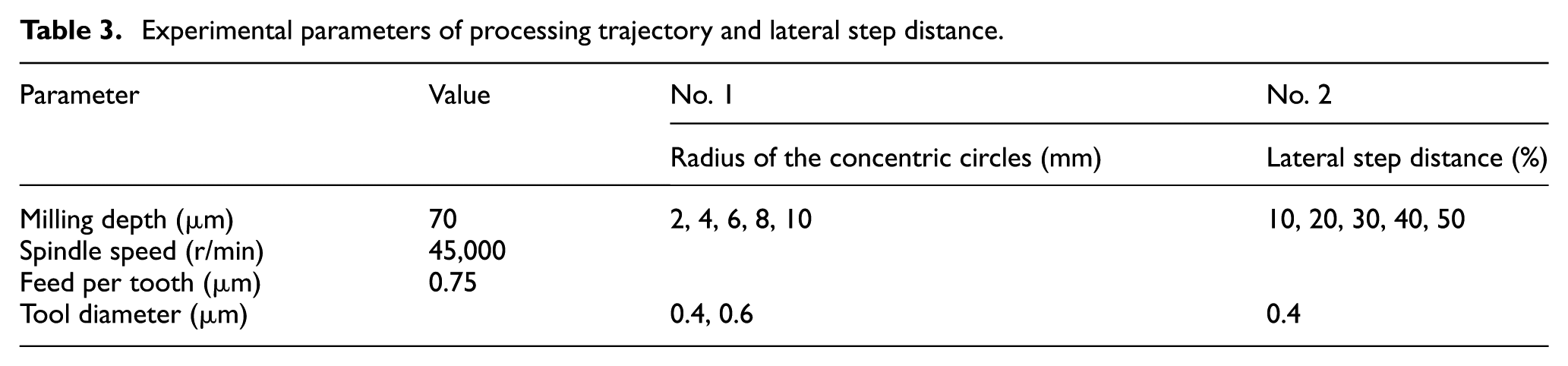
Experimental parameters of processing trajectory and lateral step distance.
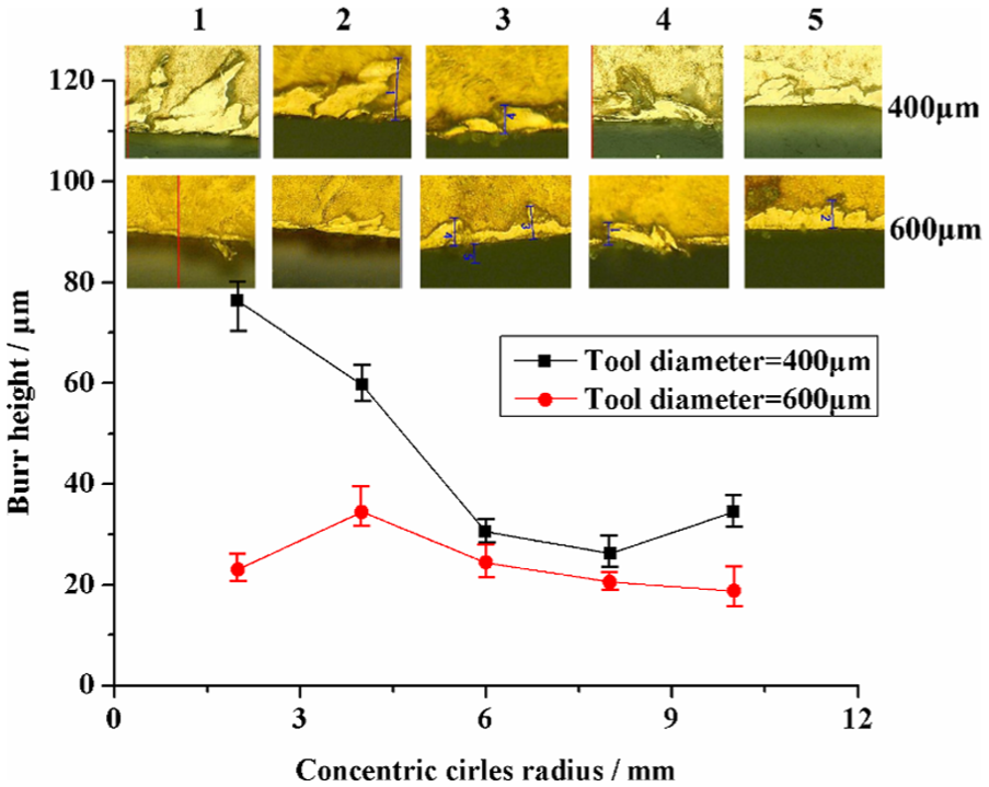
Variation of burr height with the radius of the concentric circles.
Effect of lateral step distance
To analyze the effect of lateral step distance on burr formation, the processing parameters are selected as shown in Table 3 (no. 2). The experimental results are shown in Figure 8. When the lateral step distance is small, the cutting amount is relatively small. Because of the limited binding force, copper layer is more easily to be peeled off compared with single-groove milling. Hence, a lot of burrs caused by the warped copper edge emerge. When the lateral step distance reaches up to 30% of the tool diameter, the minimum burr height can be obtained. It is because the cutting amount is larger than before and the binding force is larger simultaneously. There will be a balance between cutting force and binding force; hence, the machining process is more stable than small lateral step distance condition. With the growing of lateral step distance, the cutting force becomes larger which will break the balanced condition. Meanwhile, the cutting force on the micro-milling cutter is imbalanced because of the one side machining process that may cause the vibration of tool. In this case, the burr height increases drastically and the contour accuracy reduces, so as to make it not suitable for using.
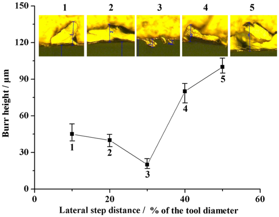
Variation of burr height with lateral step distance.
Morphological classification of burrs in micro-milling of CCPI
It is found through a large number of experiments that there are various kinds of burrs that appear in micro-milling of CCPI. The classification13,19 and generation mechanism of different burrs are summarized as follows according to shape, location and formation mechanism, as shown in Figure 9.
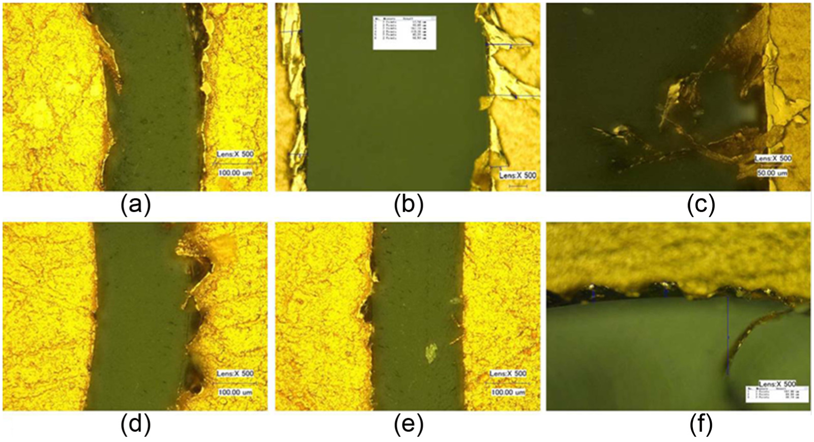
Various types of burr observed in micro-milling of CCPI: (a) rollover-type burr, (b) banner-type burr, (c) tear-type burr, (d) wave-type burr, (e) needle-type burr, and (f) occasional large burr.
The rollover-type burr, as shown in Figure 9(a), is generated by the upward component force brought by the helix angle of micro-milling cutter blade. The height of this burr is small, but it is relatively continuous. All kinds of burrs are the variants of this burr.
When the tool becomes difficult to cut off copper layer smoothly, the banner-type burr begins to appear, as shown in Figure 9(b). This burr height is larger than that of the rollover-type burr, while the burr length is relatively uniform.
With the increasing cutting amount, the cutting force increases dramatically. When the cutting force is larger than the binding force between copper layer and PI substrate, the copper layer starts to be peeled off from the PI substrate. In this case, the copper layer is torn by micro-milling cutter instead of cutting off. Therefore, the tear-type burr appears, as shown in Figure 9(c).
When spindle speed is high or tool overhang is large, the instability of micro-milling cutter dynamic balance and run-out error will significantly increase. As a result, the wave-type burr is formed as shown in Figure 9(d). Once such kind of burr occurs, it often tends to be persistent unless the micro-milling cutter is reset or the spindle speed slows down.
In addition, there will be some needle-type burrs left on the edge when large burrs are ruptured, as shown in Figure 9(e). Meanwhile, due to the inhomogeneity of the coating material itself, some occasional large burrs exist, as shown in Figure 9(f).
Processing optimization for micro-milling of CCPI
The skin effect makes current flow along with the surface and the edge of metal pattern. When the boundary is neat, the current can go through easily and will not bring loss or interference. When large burr exists, the current cannot pass through directly which will lead to severe energy loss, signal distortion and other hazards. As processing parameters and tool diameter have great influence on burr height according to the former investigation, it is of great importance to perform an optimization for them.
Establishment of burr height model
In this study, response surface methodology (RSM), which is a kind of statistical method, is used to establish burr height model. The goal of RSM is to set up an approximate function between input factors and output value by a series of experiments and statistic analysis. The related variables are put into action through a second-order polynomial expression with high efficient. According to the principle of Box-Behnken design and the experiment results above, three factors and three levels of response surface analysis method is used, and a quadratic mathematical model of burr height is established. Contour and response surface of burr height produced in machining are plotted, which reveals varying laws of burr height under different spindle speeds, feeds per tooth and tool diameters.
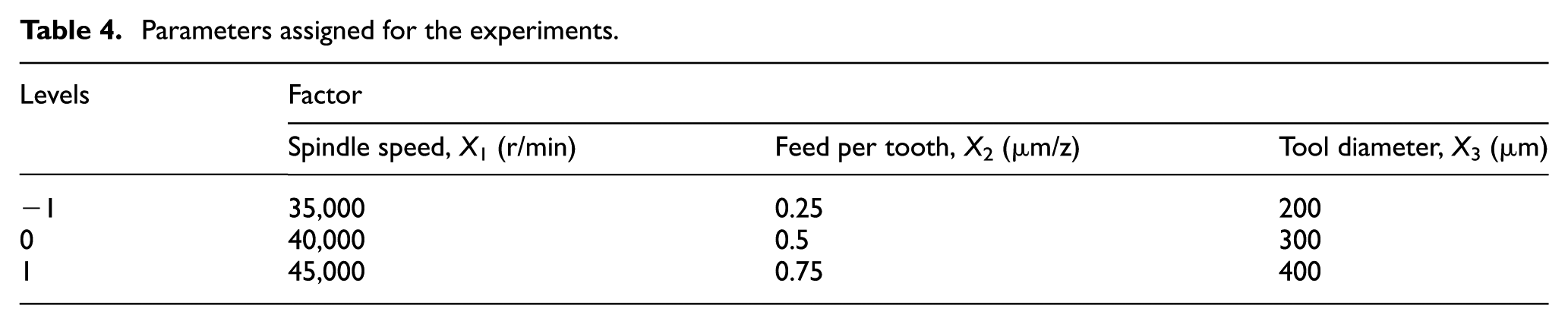
As different parameters have different variation ranges and for the convenience of data processing, all the independent variables need a linear transformation, through which the problems caused by the difference of unit can be solved. The detailed step for encoding is as follows:
The variables can be coded according to equation (1), in which
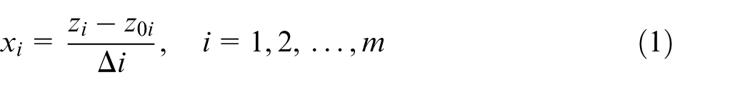
Parameters assigned for the experiments.
According to the experimental design, helical slots are machined with different combinations of the processing parameters, and different burr heights are measured as shown in Table 5.
Experimental design and results.
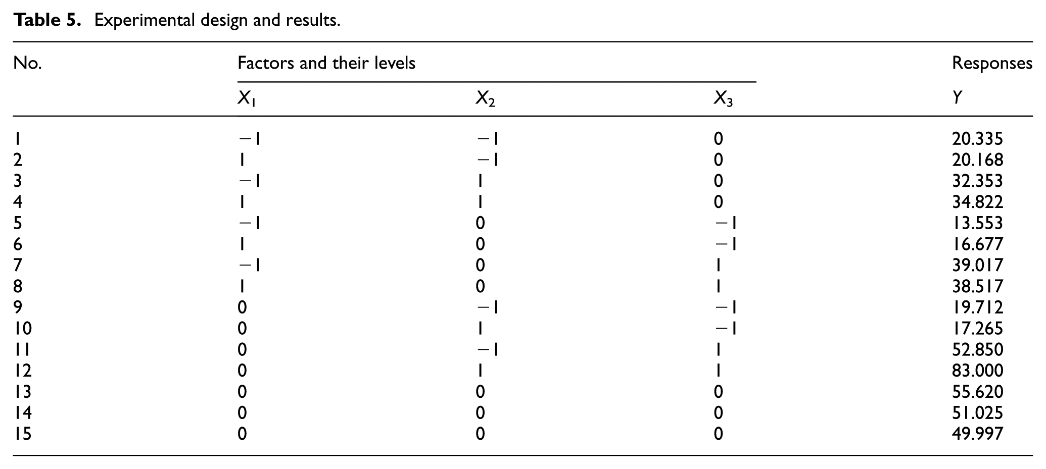
Based on the above data, a regression equation with respect to the spindle speed (X1), feed per tooth (X2) and the tool diameter (X3) is obtained, as shown in equation (2)

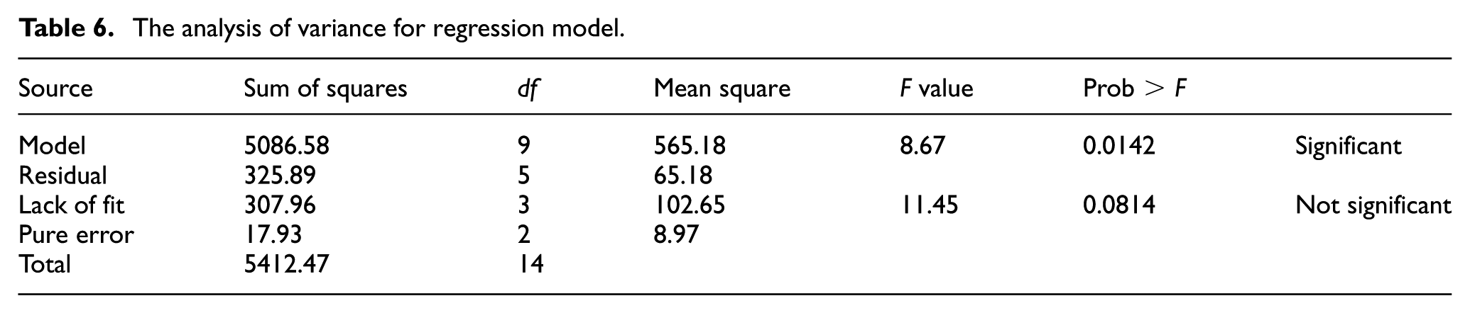
In addition, the significance of the model is tested, and the results are shown in Table 6. The significance tests for the coefficient of regression model are conducted, and the results are shown in Table 7.
The analysis of variance for regression model.
Significance tests for the coefficient of regression model.
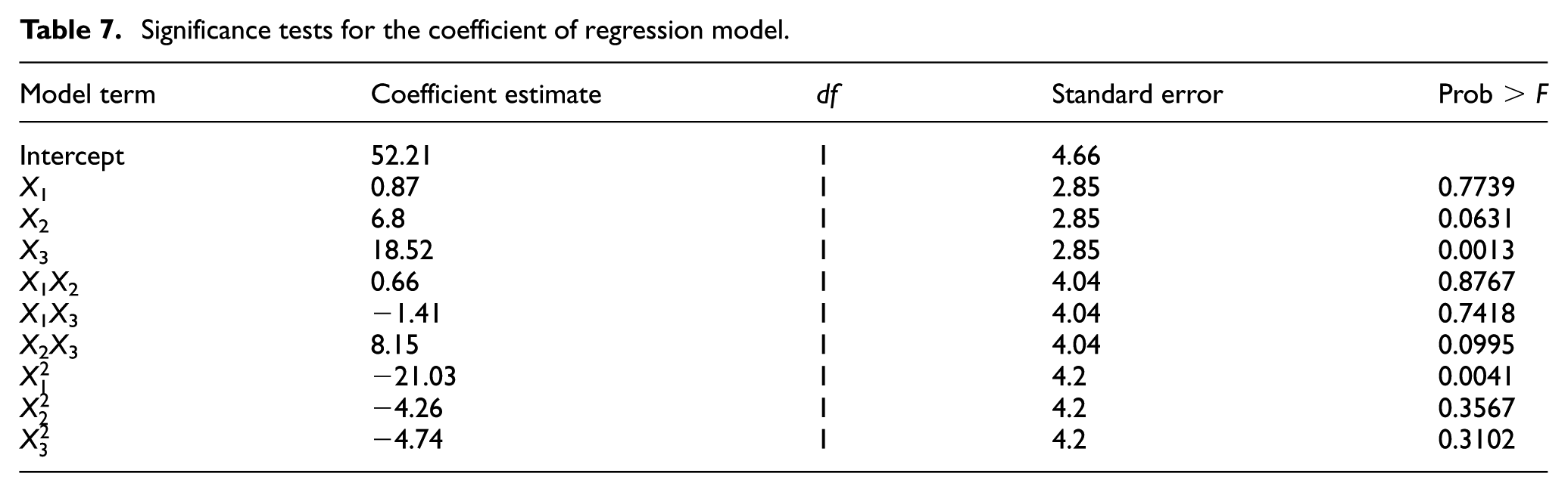
When the value of Prob > F is <0.05, the model is significant, and when the value of Prob > F is >0.1, the model is not significant. From Table 6, it can be seen that the regression model is significant, and lack of fit is invalid. Meanwhile, the multiple correlation coefficient R = 0.9398 indicates that the regression level of this model is high, and experimental error is small. Therefore, the model can be applied to predict burr height. From the result of significance test, X3 and
Processing parameter optimization
When the tool diameter D = 300 µm, the varying law of the burr height with different feeds per tooth and spindle speeds are shown in Figure 10. From this figure, it is seen that when the spindle speed ranges from 35,000 to 40,000 r/min and the feed per tooth ranges from 0.25 to 0.7 µm/z, the burr height increases continuously to 50 µm. Then, with the growing of the spindle speed, there is a decreasing trend of the burr height and reduces to 30 µm. Therefore, a better processing quality can be obtained when the spindle speed is 35,000 or 45,000 r/min.
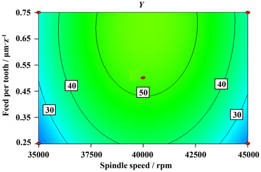
Interaction effects of feed per tooth and spindle speed.
When the feed per tooth is 0.5 µm/z, the impact of tool diameter and spindle speed on burr height is illustrated in Figure 11. It can be seen that the burr height increases continuously with tool diameter, when the spindle speed ranges from 35,000 to 40,000 r/min and the tool diameter ranges from 200 to 400 µm. When the tool diameter remains constant, the burr height increases at first and then decreases with the increasing spindle speed. The maximum burr height of 60 µm occurs when the tool diameter is 400 µm and the spindle speed is 40,000 r/min.
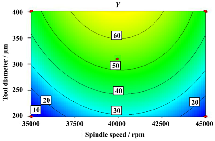
Interaction effects of tool diameter and spindle speed.
When the spindle speed is 40,000 r/min, the impact of tool diameter and feed per tooth on burr height is illustrated in Figure 12. The results indicate that when the range of feed per tooth is 0.25–0.75 µm/z and the range of tool diameter is 200–400 µm, the burr height increases from 20 to 70 µm linearly. Thus, a better processing quality can be acquired using a smaller feed per tooth and tool diameter.
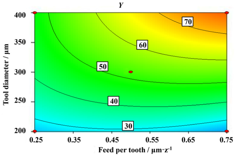
Interaction effects of tool diameter and feed per tooth.
The contour shape reflects the strength of interaction between two factors. Oval contour line represents significant interaction between two factors, and round contour line represents non-significant interaction between two factors. Therefore, the interaction between spindle speed and feed per tooth and spindle speed and tool diameter is weaker than that of feed per tooth and tool diameter, as shown in Figures 10–12. Through analyzing these three groups of contour graphs, tool diameter has the greatest impact on burr height, which is manifested by the dense contours and the quickly changed height. Minimum burr height emerges when the tool diameter is 200 µm. Otherwise, the effect of spindle speed and feed per tooth on burr height is slightly smaller than that of the tool diameter.
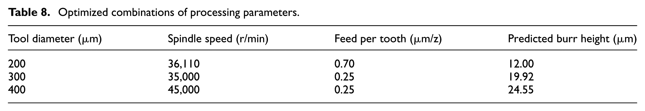
Optimized processing parameter combinations are obtained through analysis of the regression equation in equation (2). In order to meet the engineering requirements, the burr height should be as small as possible and the feed rate should be as high as possible for better quality and efficiency. The predicted minimum burr height when using different tool diameters is shown in Table 8.
Optimized combinations of processing parameters.
The validation experiments are performed with the spindle speed of 36,110 r/min, feed per tooth of 0.70 µm/z and tool diameter of 200 µm, and the results are shown in Figure 13. Measured by microscopic measurement, the average burr height is 13.9 µm. Due to the instability of copper layer on CCPI, the actual value of burr height is slightly larger than theoretical prediction, while the quality of circuit pattern edge can still satisfy the requirement. The error between predicted value and experiment value is 15.8% which is <20%. The result is acceptable and indicates the correctness of this method.
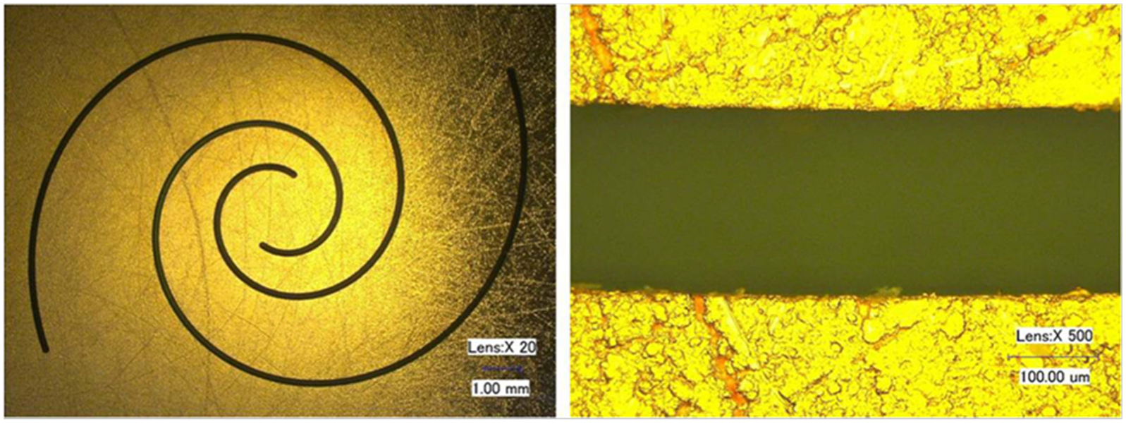
Micrographs of the helix grooves (spindle speed = 36,110 r/min, feed per tooth = 0.7 µm/z and tool diameter = 200 µm).
Conclusion
This article presented a parametric optimization method for machining CCPI based on burr height. According to the experimental results, morphological classification and mechanism analysis of burr formation are explored. Furthermore, a prediction model of burr height is established using RSM, and the optimized processing parameters are obtained based on the prediction model. Some conclusions obtained are as follows:
Due to the insufficient rigidity of cutting system, large burr is generated when the cutting depth is small. When the cutting depth is in a normal range, the cutting depth actually has little influence on burr height.
The burr height is sensitive to the tool path curvature. It grows with the increasing tool path curvature, especially for small diameter cutting tool.
The RSM optimization results indicate that each tool diameter is corresponding to a group of processing parameters with which the minimum burr height can be obtained. The validation experiment is performed to prove that the burr height which can satisfactorily meet the requirement can be obtained with the optimized processing parameter combination.
This research provides an effective approach for reducing burr height in micro-milling of CCPI and the achievements are of vital importance for improving machining quality and efficiency of CCPI.
Footnotes
Acknowledgements
Zhenyuan Jia sincerely acknowledges permissions regarding reprint or reuse of figures from publications from Elsevier and IOP. The authors thank the anonymous reviewers for their comments which led to the improvement of this article.
Declaration of conflicting interests
The author(s) declared no potential conflicts of interest with respect to the research, authorship and/or publication of this article.
Funding
The author(s) disclosed receipt of the following financial support for the research, authorship, and/or publication of this article: The project is supported by the National Basic Research Program of China (No. 2014CB046503), Science Fund for Creative Research Groups (No. 51321004) and National Natural Science Foundation of China (No. 51205041).