
Abstract
Trajectory planning of aspherical surfaces with appropriate cutting parameters is always a tedious task, especially on difficult-to-grind materials. Orthogonal experiments are usually designed and conducted first to get a full estimation of forces under different sets of grinding conditions (e.g. depth of cut and feeding velocity). However, all these data will change, as the grinding wheel becomes blunt. To reduce the work on the selection of grinding parameters and keep the grinding process stable, a new force-controlled grinding strategy for large optical grinding machine on brittle material is proposed. The grinding force is controlled by adjusting feeding velocity along the trajectories in real time. The grinding force model is established by analyzing the complex contact area between the arc-shaped wheel and the workpiece. The co-existing of brittle and ductile removal is also considered. For the longtime delay of the system, the controller foresees the grinding force in 0.4 s later based on the model proposed, to prevent the large overshoot of the force (up to 87.5%). The verification of the controller was conducted on silicon carbide ceramics. The force overshoot was reduced to 22.5%, and the motion accuracy was guaranteed by position servo within 5 µm. The subsurface damage along the trajectory was further analyzed and discussed.
Introduction
Trajectory planning of an aspherical or freeform surface is always a tedious task for machine operators. Appropriate cutting parameters need to be selected at different depths of cut. Grinding of these complex surfaces usually requires a point-contact manner between wheel and workpiece. Arc envelope grinding method (AEGM) significantly increased wheel life and improved form accuracy.1,2 However, manufacturing difficult-to-grind materials such as silicon carbide (SiC) ceramics with a long process time is still a tough task. Once dulling of wheel occurs, excessive increase of grinding force and vibration will deteriorate machining accuracy, surface quality, and wheel life.3–5
With the increasing requirements for intelligent, self-adjusting, and unattended machining system, a variety of sensors have been applied to machine tools6,7 and decision-making is automated by programs. 8 Online force control provides an effective way to keep grinding process stable and significantly reduce the workload on trajectory planning. Many strategies have been applied to control machining force. Force feedback, as a common way to gain process information, is further studied in this article. Standard proportion-integration (PI) or proportion-integration-differentiation (PID) controller may face its deficiency caused by the variation of the process transfer behaviors. Besides, the transmission behavior of the control path usually shows a time delay affected feature. Adaptive control system can react to the changing transfer behavior and adjust controller parameters, but they cannot prevent high overshoot of the force. 9 Thus, for a system with large inertia and longtime delay, a model-based predictive controller was proposed to predict future machining behavior. 10 Altintas and Aslan 6 solved the problem of large force overshoot in another way. An adaptive controller with 1 s look-ahead force prediction was proposed in the milling process.
Many models have been established to predict grinding/cutting forces, including numerical analytical models, regression models, and neural network models.
11
Grinding parameters, such as depth of cut
The motivation of this article is to present an effective online force control system for a large optical grinding machine. A grinding force model was established first to provide force prediction. The parameters of the model were identified by a set of grinding force experiments. In order to ensure the control performance, the parameters were re-identified according to the data in previous force control experiments and the data sheet in the motion controller was updated before the tests with force prediction. The grinder self-adjusts the trajectory velocity by force feedback control. To prevent large overshoot of the grinding force due to the longtime delay and the large inertia of the moving part, the controller foresees the grinding force with 0.4 s look ahead of the trajectory. The performance was verified through the grinding experiments on SiC ceramic with a three-axis grinder. The subsurface damage (SSD) along the grinding trajectory was further analyzed and discussed. The physical configuration of this approach is shown in Figure 1.
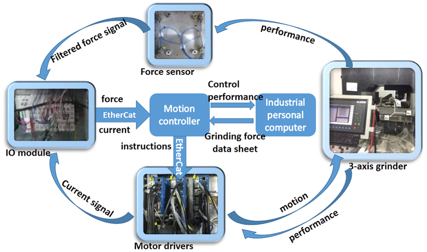
The physical configuration of the force-controlled grinding system.
Grinding force modeling
Trajectory planning
Different from the conventional five-axis grinding, in AEGM, the workpiece surface is formed on a three-axis grinder by controlling the trajectories to ensure that the normal vector at the grinding point on the arc-shaped wheel is aligned with that on the target surface.2,15 The profile of the grinding wheel is shown in the tool coordinate
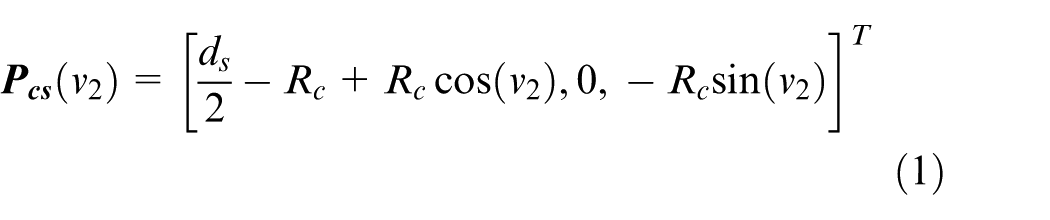
where
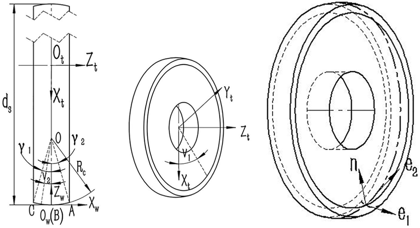
Parametric surface of arc-shaped wheel.
In this study, a T
3
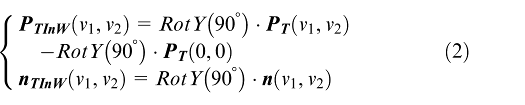
-configuration machine tool, which means that it has three mutually perpendicular linear axes, is adopted. To solve the three-axis motion, the grinding wheel surface and its normal vector are expressed in the workpiece coordinate
The aspheric surface equation and the normal vector are expressed as
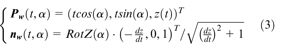
where the generatrix of aspheric mirror
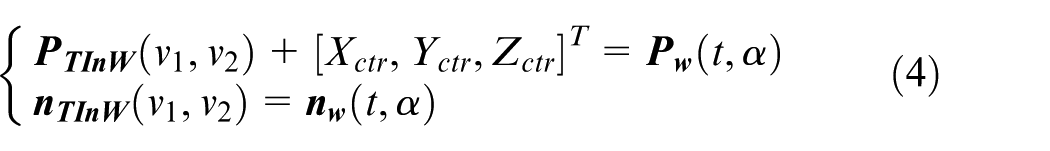
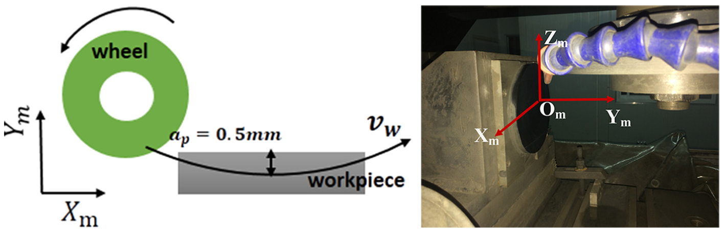
Grinding points on a trajectory share the same latitude coordinate (see Figure 3(a)). This trajectory planning method is called parallel grinding mode. 15 For each grinding point, the curvatures on the grinding wheel and the workpiece need to be checked to ensure the motion feasibility. To achieve the target surface, several intermediate surfaces are generated, and the generatrices of the surfaces are shown in Figure 3(b). In the experiments, the test samples were flat surfaces. An arc trajectory, the maximum depth of cut of which is 0.5 mm, was used to adjust the controller parameters and test the proposed controller.
Parallel trajectory planning for a mirror. (a) Parallel trajectory planning for a mirror and (b) Arrangement of the grinding processes.
Wheel-workpiece contact area
For a given trajectory, the tangent feeding direction
Detailed analysis can be conducted based on the above assumptions. In the frame
where
Feeding direction
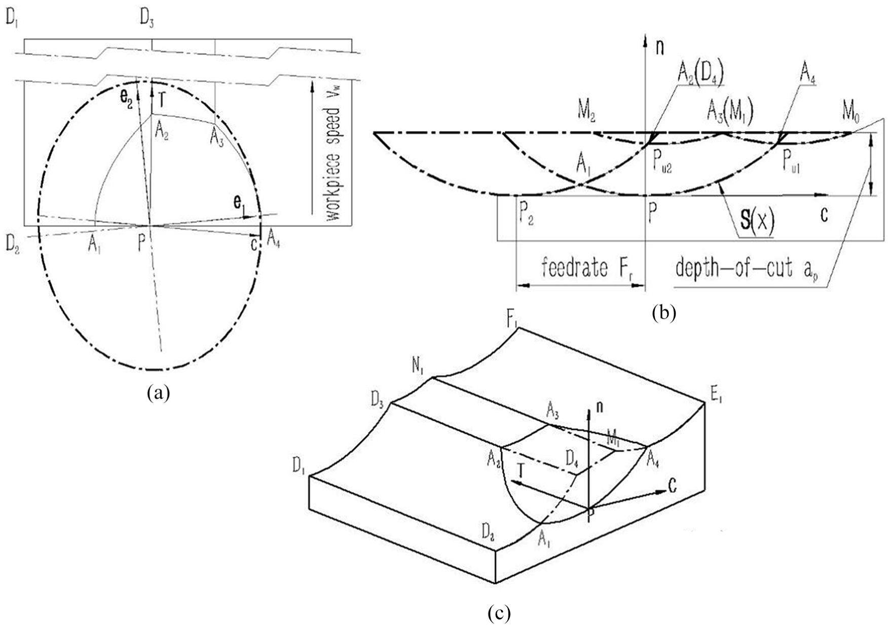
The wheel-workpiece contact area. The wheel-workpiece contact area: (a) top view, (b) front view and (c) 3D view.
According to the above assumptions, the wheel motion enveloping surface near

The boundaries of the wheel-workpiece contact zone (i.e., A1A2, A2A3, A3A4, A4A1) are solved by the ruled surfaces D1D2D4D3, D3D4M1N1, M1E1F1N1 and the wheel equivalent surface—elliptic-parabolic surface (see Figure 4(c)).
Distribution of undeformed chip thickness
In this article, the grits are assumed to be uniformly distributed on the wheel surface. The contact area is divided into several pieces along the rotation axis of the wheel according to the average grit distance (see Figure 5(a)). Each slice of the grinding wheel can be regarded as a disk-shaped wheel (see Figure 5(b)). The number of active grits per unit area C is calculated by the equation,
16
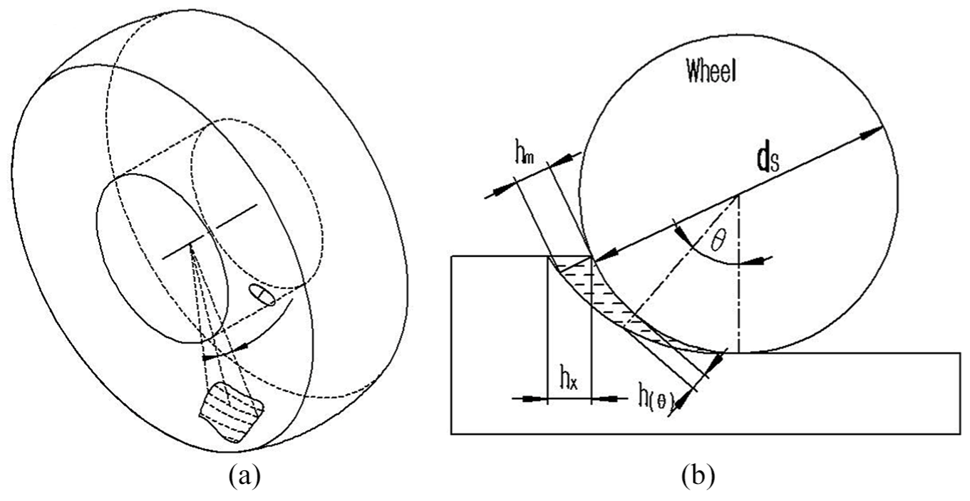
(a) The division of contact area and (b) grinding kinematics.
Based on the assumption
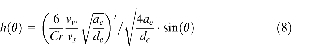
where r is the ratio of chip width to height,
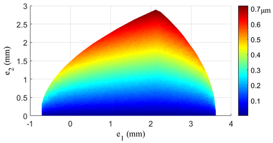
Distribution of UCT for parallel grinding (
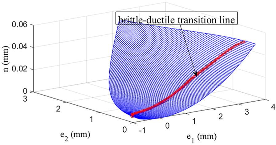
Brittle–ductile transition line in the wheel-workpiece contact area (
Calculation of grinding force
The normal grinding force is calculated by the sum of all the individual grit forces in the contact area
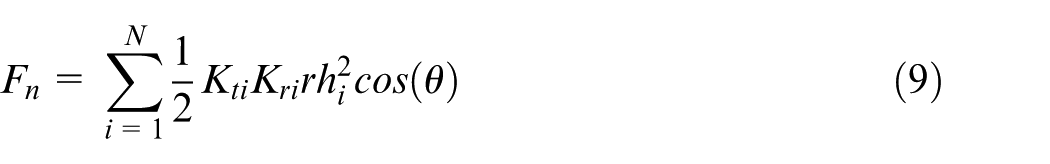
where N is the grit number in the contact area,
The critical depth of cut (CDC) is about 180 nm for SiC ceramic from the grinding experiments of Bifano et al.
20
If estimated by the equation,
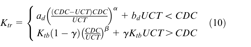
From the grinding experiments investigating specific energy, the relationship between dimensionless
Online grinding force control scheme
The CNC trajectory is fitted by a high-order polynomial and expressed as
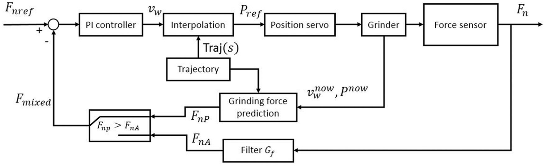
Schematic of feeding velocity self-regulation system.
There are six buffers in the motion controller used to realize the online force control. All buffers are executed in parallel and each program line takes 1 ms. Thus, the script needs to be written as short as possible. Buffer 1 is used to collect force data, Buffer 2 gives a time tick every 10 ms, Buffer 3 gives force prediction to the PID controller, Buffer 4 executes the motions, Buffer 5 calculates the interpolation points on the trajectory, and Buffer 6 is the PID controller. The C+ + code, written in the “onTimer” function of the “ViewProgram” Class, is designed to communicate with the motion controller and control the start/stop of the buffers. The timer is set to 100 ms. The software configuration is shown in Figure 9. The detailed program flowchart is shown in Figure 10.
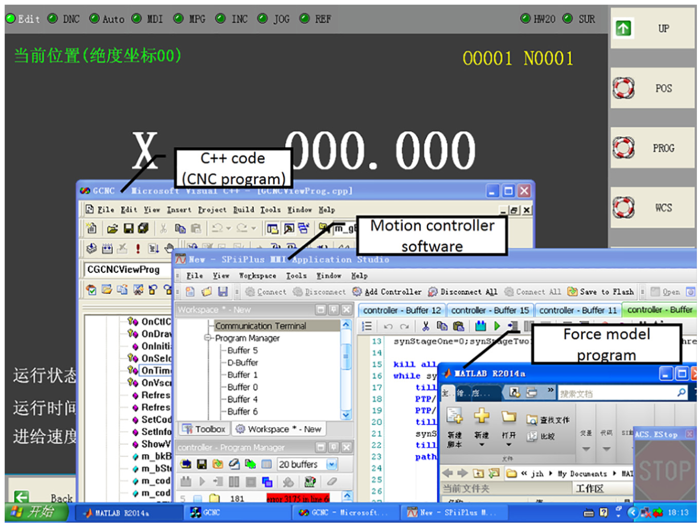
Software configuration of the control system.
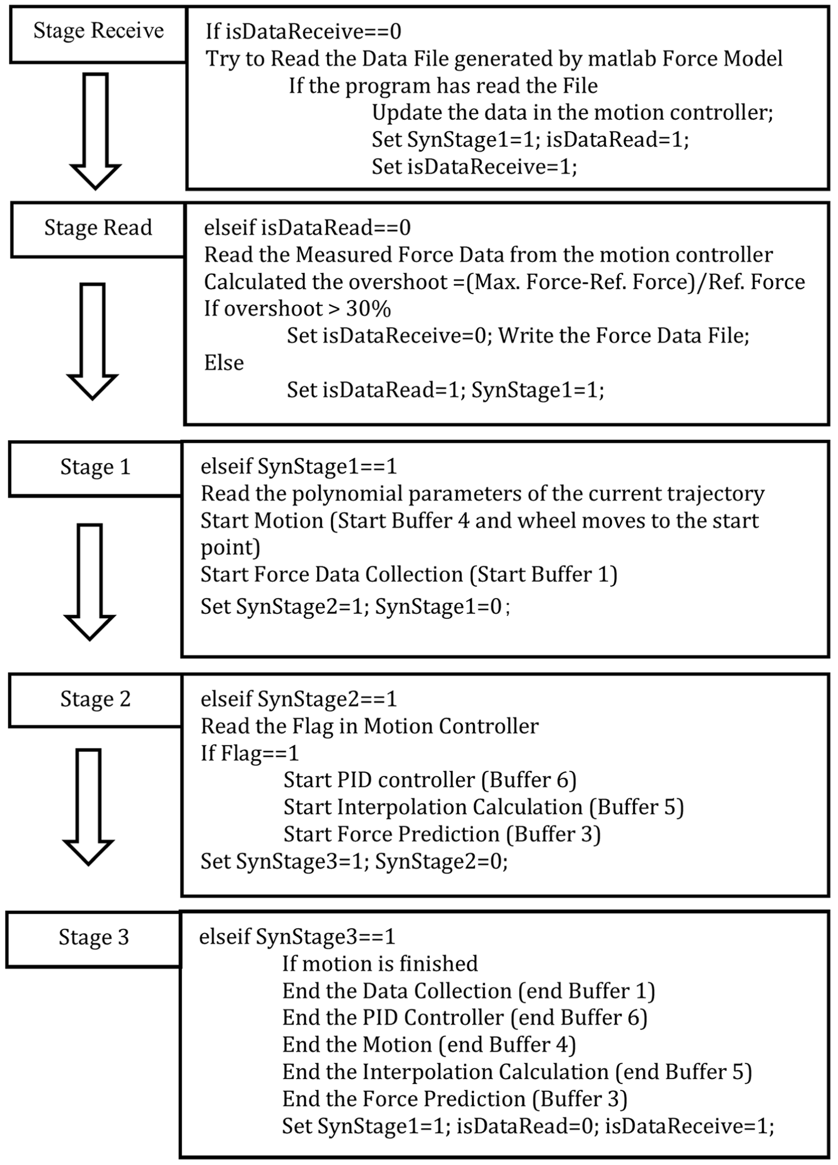
Program flowchart of the main C++ code.
In order to realize the data exchange with the force model coded in MATLAB, the measured force data will be written into a .txt file, if the overshoot of the force exceeds 30%. In MATLAB, a script coded with “while” loop keeps trying to read this file. Once successfully read in, the program will start to identify the parameters in the force model. When finished, a new grinding force datasheet will be written into a .txt file. Then the file of the measured force data will be deleted, and the “while” loop continues to run empty until a new force record is generated again.
Experimental research
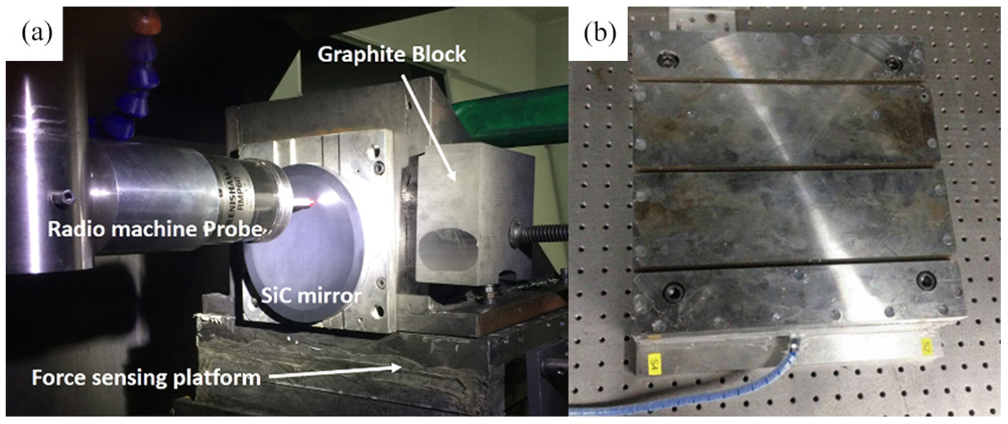
The experiments are aimed at validating the proposed force-controlled grinding method with arc-shaped wheel. The experimental configuration mainly consists of a force-sensing platform, a radio machine probe, a 135 mm-diameter hot-pressed sintered SiC-ceramic sample, an arc-shaped wheel, and a three-axis high-precision grinder, as shown in Figure 11. The grinder has an axial resolution of 1 µm in the X- and Y-directions and 0.5 µm in the Z-direction. A hydrostatic spindle with a radial runout less than 1 µm is mounted vertically on the Z-axis. In the experiment, the wheel axis and the workpiece axis were perpendicular to each other. A #200 resin-bonded diamond arc-shaped wheel was used and its parameters are listed in Table 1.
(a) Three-axis grinder and (b) force-sensing platform.
Parameters of the resin-bond grinding wheel.
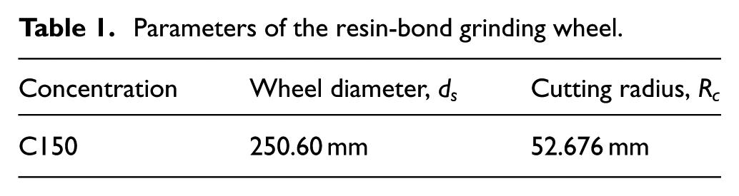
The wheel was trued by GC (green silicon carbon) wheel. This method showed fine truing performance to achieve high-efficiency grinding in Chen et al.’s 30 study. The actual values of the wheel diameter and the cutting radius were identified by measuring the wheel surface printed on the graphite block (see Figure 11). The radio machine probe is provided by Renishaw, Inc. (model: RMP60) with 1 µm repeatability. The force-sensing platform includes four triaxial force sensors (PCB Piezotronics, Inc., model: 260A12) located on its corners inside. Analog input/output (I/O) module (WAGO, Inc., sample rate: 100 Hz) is used for data acquisition. The force signal is filtered by a three-order low-pass Butterworth filter before connected to the I/O module. The cutoff frequency of this filter is 15 Hz. The force control strategy is programmed in the buffers of the motion controller (ACS Motion Control, Inc.). The sample rate of the force control loop is 100 Hz.
An arc trajectory was used to test the control strategy on a flat surface. The radius of the trajectory is 4692 mm and its maximum depth of cut is 0.5 mm (see Figure 12). The wheel rotation speed was 1800 r/min. The feed rate
Experiment setup.
Parameter identification of grinding force model
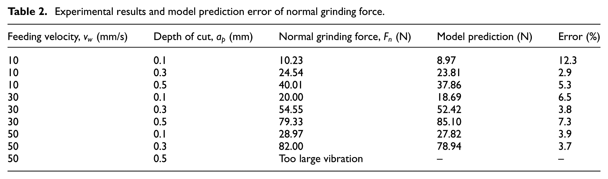
To identify the parameters, a set of grinding force experiments were conducted first, the data of which are listed in Table 2.
Experimental results and model prediction error of normal grinding force
In the previous works,
Model parameters
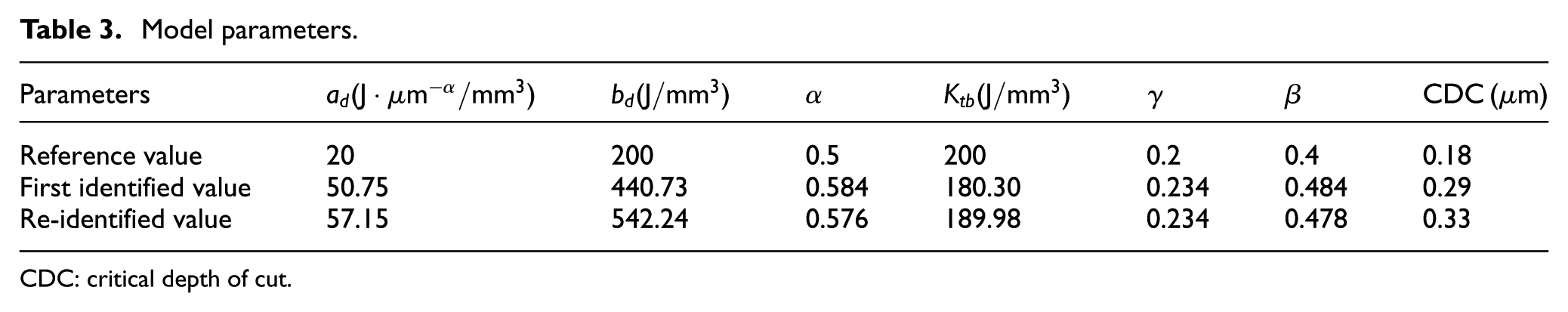
CDC: critical depth of cut.
The force model is considered as a regression model here. The least square method is used to identify the best-fit parameters. The MATLAB “fminsearch” function is used to search the solution. The objective function is established by calculating the quadratic sum of the error between measured force data and estimated force data. The optimization algorithm was started with different sets of initial values to avoid the local minima value. It took a long time to find the first identified result. The estimated values of grinding force model and its prediction errors are listed in Table 2. Most prediction errors are less than 10%. The maximum error appears at vw = 10 mm/s and ap = 0.1 mm, and almost has no impact on the control performance, as the force is only about 10 N.
Before the tests, the sample was ground flat. The wheel was not re-trued, and 18 grinding tests were conducted to adjust PI parameters before finally testing the controller with force prediction. Considering dulling of the grinding wheel, which may affect the control performance, the latest test data in adjusting PI parameters (only 37 points uniformly picked) were used to re-identify the model parameters. The optimization algorithm was started with the first identified values. In order to accelerate the searching progress, α, β, and γ were not considered. After ad, bd, Ktb, and CDC were optimized, the program was re-started with all seven parameters. It took 17.95 min. The final re-identified parameters are shown in Table 3. The predicted values are compared with measured data in Figure 13(b). The increase of values
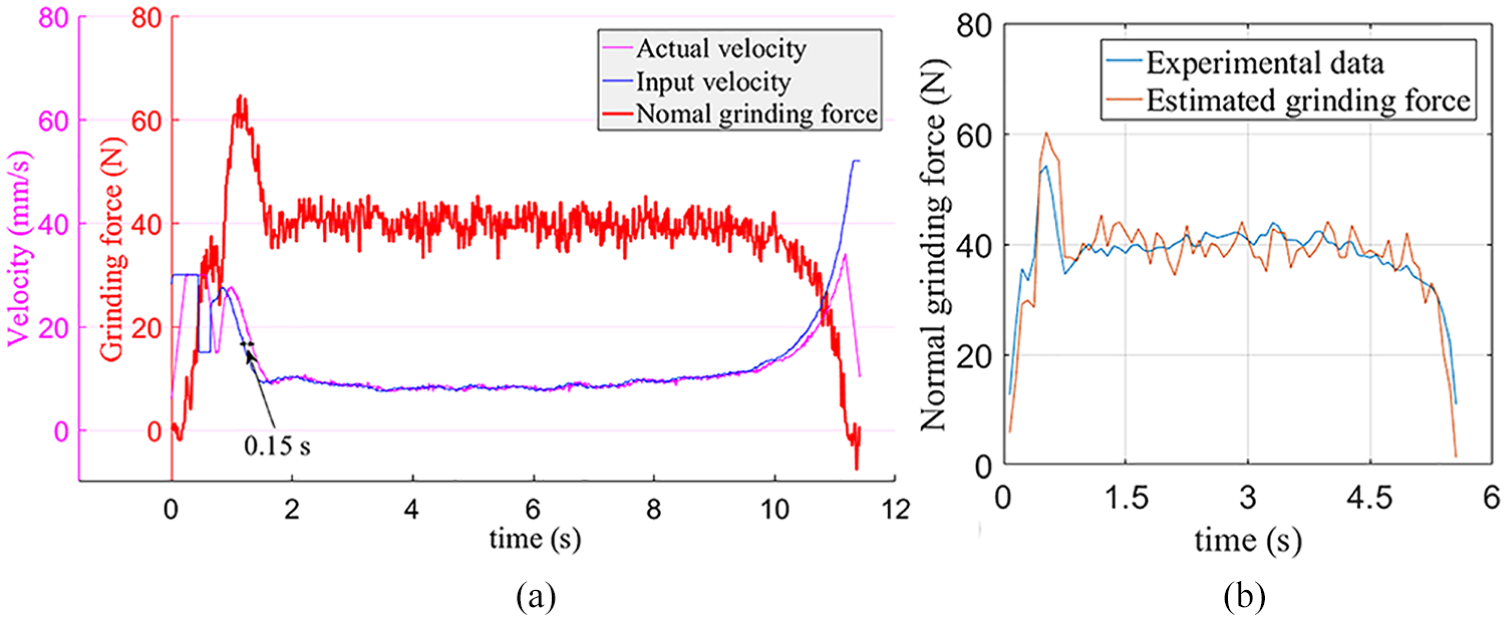
(a) Time delay of the control system and (b) the comparison of experimental data and estimated grinding force by the proposed model.
As a filter with 15 Hz cutoff frequency is added into the feedback loop, a simple script programmed in MATLAB is enough to estimate the performance of the controller. The limitation of the acceleration is set to 100 mm/s2. The simulation step is 10 ms. The units of “interpolation” and “position servo” are replaced by time delay units. Limited by the real-time operating system (OS) environment of the motion controller, the time delay between the actual tangent velocity and the input velocity is inevitable and it is 0.15 s (see Figure 13(a)). PI parameters are set as Kp = 0.1 and Ki = 0.02. The control performance with 0.4 s look-ahead time is simulated (see Figure 14).
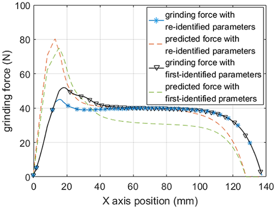
Comparison of control performances before and after parameter re-identification.
Online force control experiments
Without force prediction, the grinding wheel will contact workpiece with large force overshoot, unless the upper limit of the feeding velocity is set relatively low. To overcome the drawback, the prediction of the grinding force will be fed into the controller when the predicted force
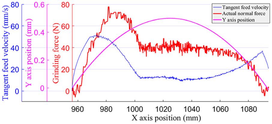
Control performance without force prediction (Kp = 0.1 and Ki = 0.02).
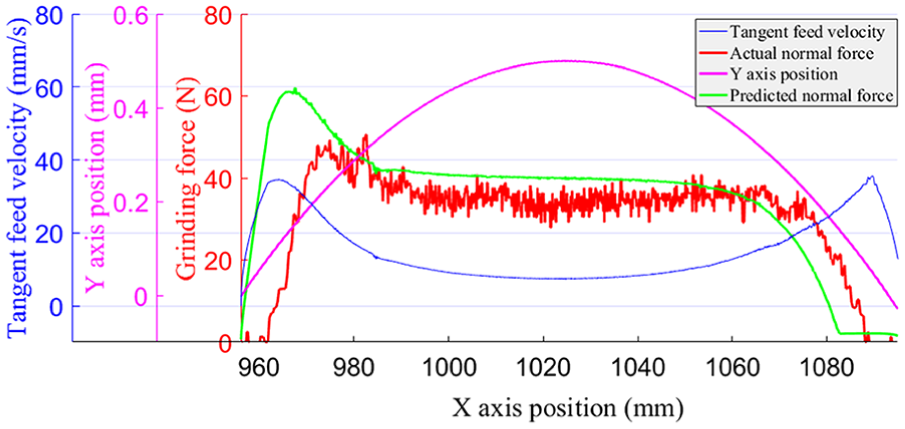
Control performance with force prediction (Kp = 0.1 and Ki = 0.02).
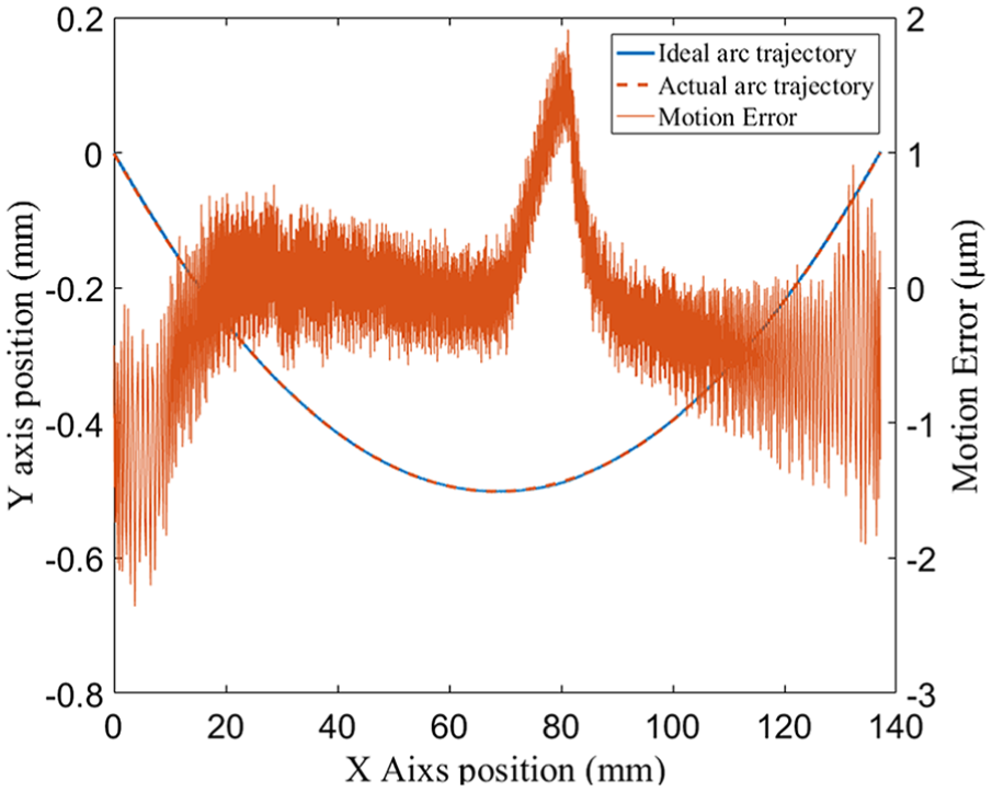
Motion error along the trajectory.
In addition, the control performance strongly depended on the estimation of the grinding force and the system time delay. In order to eliminate the overshoot, the predicted force was better to be slightly over-estimated. Alternatively, the look-ahead time was further enlarged to 1 s. The overshoot was still about 24% (see Figure 18(a)), due to the fluctuation of actual grinding force and force prediction error. For the reference force equals 60 N, the performance of the force predictor degrades (see Figure 18(c)), since the model parameters were optimized around 40 N . However, the undershoot of the grinding force is allowed.
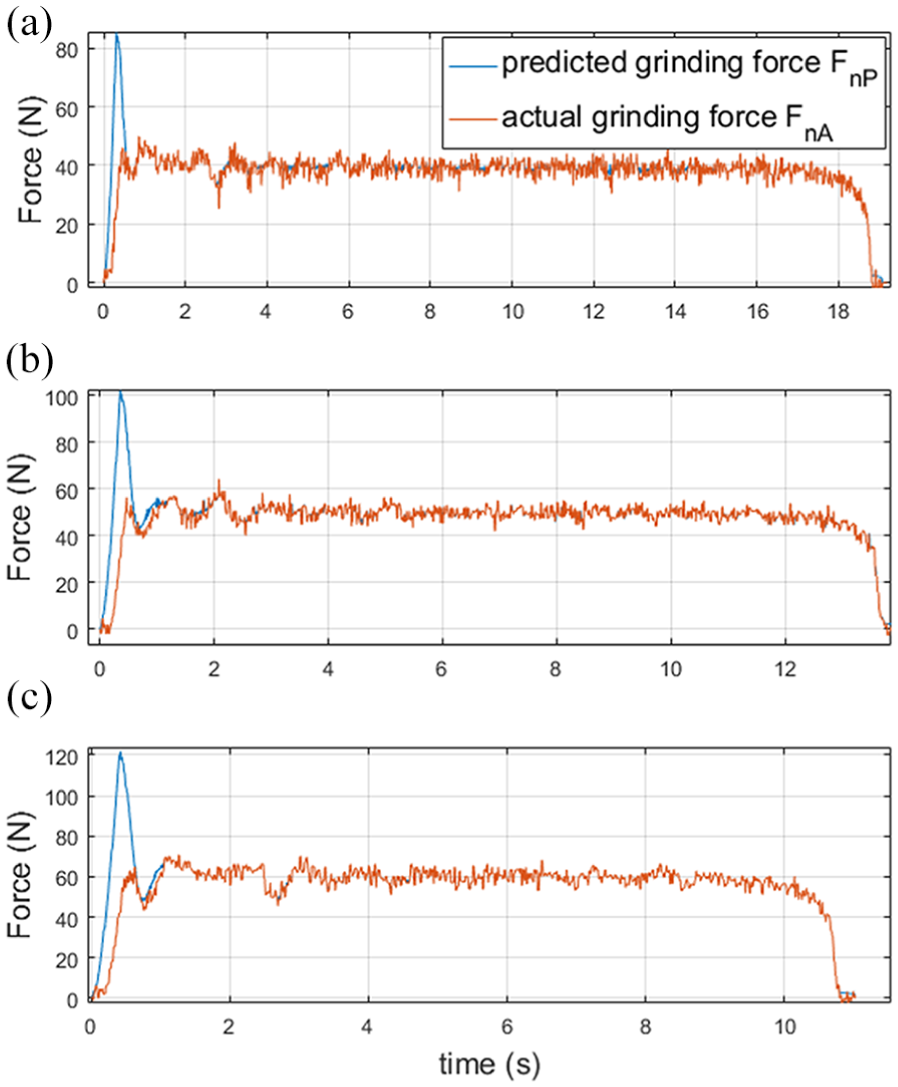
The test results of 1 s look-ahead time with reference force: (a) Fnref = 40 N, (b) Fnref = 50 N, and (c) Fnref = 60 N.
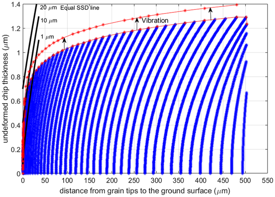
The maximum UCT of each grinding point is further studied. The calculation of the wheel-workpiece contact area and the distribution of UCT are illustrated in the “Wheel-workpiece contact area” and “Distribution of undeformed chip thickness” sections. Each point (blue) in Figure 19 indicates the vertical distance of each grit in the contact area to the ground surface and the UCT at its position. The envelope curve (red) represents the relationship between maximum UCT and depth of cut
Influence of vibration on SSD.
According to the estimated CDC (i.e. 0.33 µm in Table 3), the material is mainly removed in the brittle mode (see Figure 20). Thus, the SSD is primarily concerned. Median crack is considered as the main type of subsurface crack, which nucleates on the boundary of the inelastic zone and extends perpendicular to the surface. The relationship between median crack depth Cmi and the penetration depth hi was established by Gu et al. 32

where Km = 0.206((EHs)1/3/(Kcβ)2/3)(cotα)4/9(tanα)4/3. Hs is the scratch hardness, Kc is the fracture toughness, and β is the significant material parameter determined by elastic recovery. The apex angle of the grit 2α is 136°.
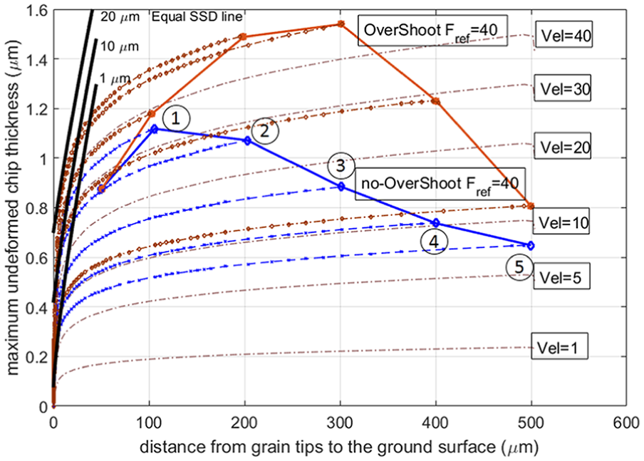
Comparison of UCT envelope curves with or without large force overshoot.
In many grinding systems, the grinding performance is mainly limited by the dynamic stiffness of the system, and larger grinding force brings larger vibration between grinding wheel and workpiece. 33 As the feeding velocity keeps constant and the vibration increases with the rise of depth of cut, the whole envelope curve of UCT will move upward and cross the original equal SSD line (see Figure 19). Chen et al. 4 also analyzed the influence of vibration on SR (surface roughness) and SSD. It was found that both larger vibration amplitude and higher vibration frequency greatly deteriorated the SR and SSD. Besides, the chatter mark is hard to be removed in the next process. In order to reduce the runout error of the grinding wheel and achieve better surface and subsurface quality, Zhao et al. 34 proposed a method by conditioning coarse-grained diamond wheel with D3 steel. Moreover, the growth of depth of cut has limited influence on SSD. Wang et al. 35 deduced the relationship between scratching depth and damage depth according to fracture mechanics. A drop of damage depth would appear when the material removal mode entered the full brittle mode. In the experimental investigation of SiC grinding by Agarwal and Venkateswara Rao, 36 the damage layer thickness grew slowly with the increase of depth of cut. In this article, the purpose of the force controller is to keep grinding force constant and vibration at the same level, and remove the material in the brittle mode with high efficiency.
The UCT envelope curves of five major grinding states in Figures 15 and 16 are plotted in Figure 20. The process without overshoot will yield better subsurface quality. However, SSD is still uneven at the Points 1 to 5, and SSD at Point 1 is the largest. Thus, the upper limit of the feeding velocity needs to be reduced (or the PI controller should be disabled to keep low and constant feeding velocity) in the final process close to the target surface. Moreover, the surface accuracy, SR, and SSD can be further improved with a constant depth of cut in semi-finish cut and finish cut with #400 and #800 grinding wheels.
Conclusion
To reduce the work on the selection of grinding parameters and keep the grinding process stable, this article proposed an effective online force control method on brittle material. The conclusions are obtained as follows:
The overshoot of the grinding force was remarkably reduced by feeding prediction of grinding force to the PI controller. To ensure the control performance, the parameters of the force model were re-identified before the tests.
From the analysis of UCT, SSD is not directly related to the depth of cut. As the depth of cut increases beyond a certain value, SSD stops growing and keeps constant. And the growth of vibration amplitude is largely responsible for the increase of SSD.
The material is mainly removed in the brittle mode to generate the target aspherical surface with high efficiency. In order to control the SSD, the force controller keeps the grinding vibration at the same level. However, the SSD is uneven and penetrates deeper at the points with higher feeding velocity. Thus, in the finish cut close to the target surface, the upper limit of the feeding velocity needs to be reduced.
Footnotes
Declaration of conflicting interests
The author(s) declared no potential conflicts of interest with respect to the research, authorship, and/or publication of this article.
Funding
The author(s) disclosed receipt of the following financial support for the research, authorship, and/or publication of this article: This work was supported by the National Basic Research Program of China (“973” Program) (Grant 2011CB013203).