
Abstract
As a large composite curved surface component, the wind turbine blade is easy to suffer from grinding burn if the grinding parameters are improperly selected during the robot grinding process, which will seriously affect the surface grinding quality. In order to effectively predict the surface grinding temperature of robot grinding wind turbine blade, the curved surface grinding heat source model was established according to the material removal depth of any grinding point in the grinding contact area, and the temperature field under different grinding process parameters was numerically simulated using finite element method. The comparison between simulation and experiment indicates that the temperature on both sides of grinding contact area is higher than the middle temperature, and the maximum grinding temperature value appears on the cut-out side of the cup wheel. The maximum grinding temperature increases as increasing the wheel speed, feed rate and maximum grinding depth, feed rate is the biggest influence factor on the grinding temperature. The maximum grinding temperature of finite element simulation is in good agreement with the experimental results and the maximum relative error is <6%. The research results reveal the variation law between the curved surface grinding parameters and grinding temperature of curved surface grinding, which provides reference and basis for the prediction of grinding temperature of the wind turbine blade ground by robot.
Introduction
As a large free form surface component, wind turbine blade need two grinding processes in the production process. With the development of science and technology, robot automatic grinding of wind turbine blade has become a development trend.1–3 The wind turbine blade is mainly composed of GFRP (Glass Fiber Reinforced Plastics) and other composites. The temperature of GFRP composites in grinding process is relatively low, and the high grinding temperature is likely to cause the surface material to soften or burn, which seriously affects the grinding quality and efficiency. Therefore, the variation of grinding temperature with grinding parameters of wind turbine blade robotic grinding was studied.
In order to accurately predict the grinding temperature under different grinding conditions, many scholars have conducted extensive research on the grinding heat source model and temperature field. Jaeger first proposed the rectangle moving heat source and analytical model of temperature field for planar grinding. 4 He et al. 5 and Mao et al. 6 put forward the heat source model of the function curve of parallel grinding wheel. The experimental results showed that the heat source of the function curve is more in line with the actual situation than the rectangle heat source and the triangle heat source. Xu et al. 7 established the analytical model of temperature field corresponding to triangular heat source in intermittent grinding of the cup wheel, and analyzed the influence trend of grinding parameters on grinding temperature. Zhang et al. 8 and Wang et al. 9 assumed that the heat flux in the grinding contact area was evenly distributed, and adopted the Jaeger moving heat source theory to establish the analytical model and numerical model for different grinding contact areas of the cup wheel. The results showed that both models could accurately describe the surface grinding temperature field of the cup wheel. Tahvilian et al. 10 proposed a heat distribution ratio model suitable for flexible robotic grinding by using simulation and experimental temperature matching methods. The results showed that the increase in feed rate and grinding power will cause the heat distribution ratio to decrease. Chen et al. 11 analyzed the grinding temperature field of carbon fiber reinforced composite materials and showed that the grinding parameters have a greater impact on the grinding temperature. Dai et al. 12 proposed a Chi-square heat source model based on the material removal mechanism of the cup wheel, and experimental verification showed that the model significantly improved the accuracy of the prediction of the temperature field of cup wheel. Pang et al.13,14 proposed the Weibull heat flux density distribution model in the study of cylindrical grinding, considering the influence of the thickness of the grinding chips and the injection speed of the grinding fluid on the shape of the heat source and the heat distribution ratio. And it was found in the experiment that with the continuous increase of the wheel speed, the increasing trend of the grinding temperature become slower. However, the heat source model does not consider the effect of grinding force distribution on heat flux in grinding contact area.
In summary, the shape of the contact area, normal grinding force distribution and the heat flux distribution of the wind turbine blade ground by the robot grinding with the cup wheel are quite different from the above studies. Therefore, it is difficult to accurately predict the grinding temperature of the robot. In this paper, based on the normal grinding force distribution in surface grinding contact area, a heat source model for curved surface grinding of cup wheel was established, and the corresponding grinding temperature field was simulated by finite element method. The influence of different grinding parameters on the maximum grinding temperature was analyzed by curved surface grinding experiment, and the accuracy of the model was verified.
Grinding force analysis of curved surface grinding contact area
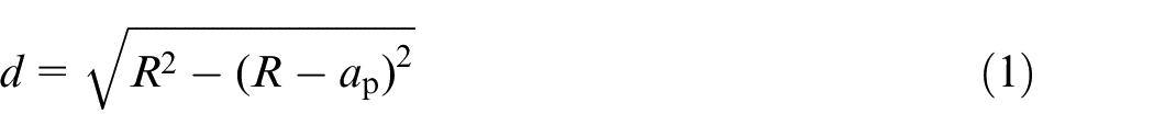
The robot mainly grinds parts with large curvature radius of wind turbine blade, and the curvature change is small at any grinding position. Therefore, during the modeling process, the wind turbine blade was simplified to a cylindrical surface with a radius of curvature of R, and the surface grinding process is shown in Figure 1. The normal line at the midpoint O1 of the width of the cup wheel is selected to coincide with the normal vector at any grinding position on the surface. If the maximum grinding depth is ap, the grinding width is lAB from the geometric relationship. The grinding depth on the line segment lAB is the maximum grinding depth ap. Therefore, lAB is used as the effective grinding width. According to the maximum grinding depth and the curvature radius of the workpiece, the heat source width d in the feed direction can be obtained as in equation (1)
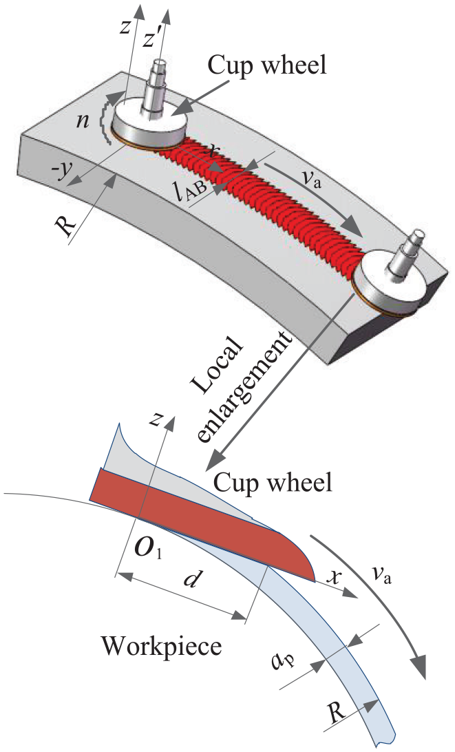
Process of curved surface grinding.
The grinding surface of the cup wheel is a circular plane with an outer diameter r1 and an inner diameter r2, and the radius of any grinding point in the ring is r. According to the width of heat source d and the size of cup wheel, the grinding contact area is determined as shown in Figure 2, its expression is as shown in equation (2)
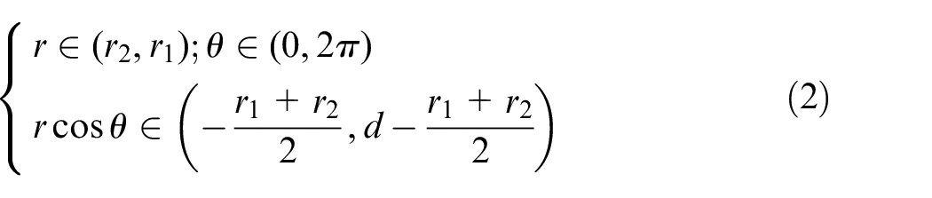
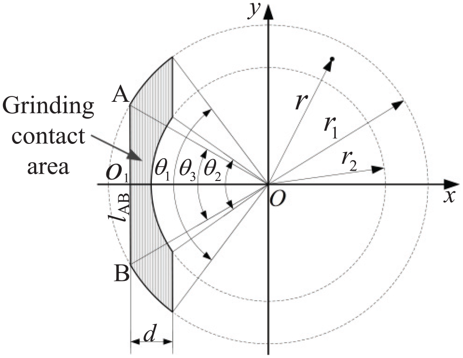
Grinding contact area.
In the curved grinding contact area, the distribution of normal grinding force at different grinding depth is different due to the existence of the curved surface, which affects the heat flux density distribution. 15 Therefore, based on the curved surface grinding material removal mechanism, a normal grinding force distribution expression was established. The grinding contact area was divided into numerous grinding lines parallel to the y axis. According to the geometric relationship, it can be known that the grinding depth on any grinding line is the same, and the normal grinding force distribution is approximately the same. The depth on different grinding lines is only related to the x axis coordinate position. If the maximum normal grinding force is p0, according to the cylindrical surface equation, the normal grinding force distribution in the grinding contact area was assumed, and its expression is shown in equation (3)
By integrating the normal grinding force per unit area of the grinding contact area, the total normal grinding force is expressed as equation (4)
The integration result in square brackets in equation (4) is expressed by φ to obtain the maximum normal grinding force p0, and p0 is taken into equation (3) to obtain the expression of the normal grinding force distribution of the grinding contact area with respect to Fn, and its expression is shown in equation (5)
According to the Preston equation of the grinding material removal rate model and the Archard tribology equation, 16 the material removal depth per unit grinding length is expressed as equation (6)
Where kapr is the wear coefficient; Hv is the hardness of the workpiece material; n is the wheel speed; dt is the residence time of any point in the grinding contact zone of the workpiece; dh is the depth of material removal in dt time.
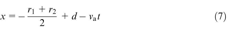
Feed rate of the cup wheel is va, the time of passing the width of heat source d is t0, and at any time t in the grinding contact area, the abscissa of the grinding point is x, which is represented as equation (7)
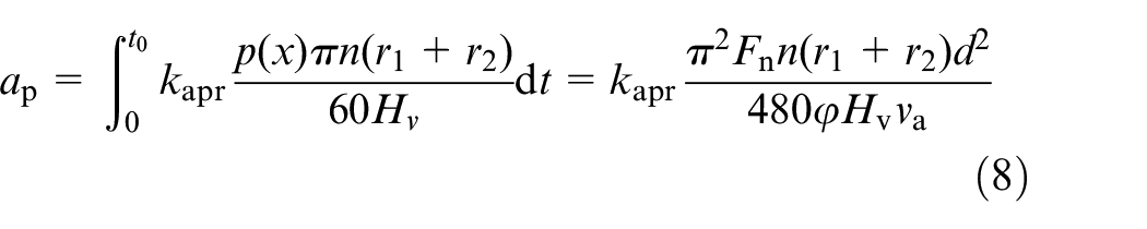
The O1 point tangential speed is approximated to the arbitrary grinding point resultant velocity in the grinding contact area, and the material was integrated in the direction of the width d to obtain the maximum grinding depth ap, its expression is as shown in equation (8)
Establishment of curved surface grinding heat source model
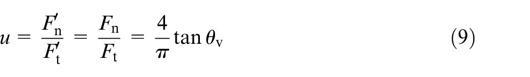
When analyzing the force of the single abrasive particle, the abrasive particle was simplified as a 2θv vertex cone, 17 and the grinding force ratio is defined as shown in equation (9)
Where
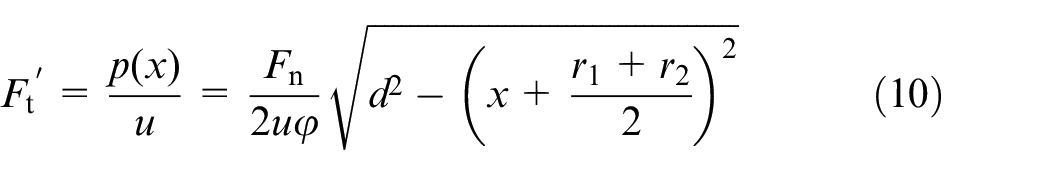
The grinding contact area was divided into numerous grinding points, and the tangential force at any grinding point is shown in equation (10)
From the power calculation formula, the total heat flux density at any grinding point is shown in equation (11)
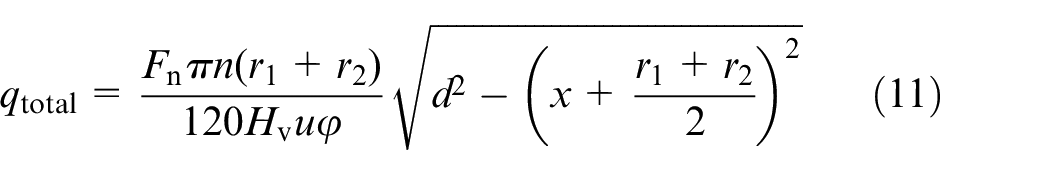
In the study of the grinding temperature field, the total heat flux density qtotal at any grinding point is mainly composed of the workpiece heat flux density qm, the grinding wheel heat flux density qs, and the wear debris heat flux density qc,18,19 its expression is shown in equation (12)

The heat flow density into the workpiece at any grinding point is shown in equation (13)

Where ηw is the heat distribution ratio between the cup wheel and the workpiece.
The heat flux density of the wear debris is related to the heat of the wear debris per unit time, 20 and its expression is shown in equation (14)

Where h is the grinding depth at any grinding point; A is the contact area of the grinding contact area; ech is the limit abrasive debris energy, 21 and its expression is shown in equation (15)

where ρw is the density of GFRP; cw is the specific heat capacity of GFRP; Tch is the melting point temperature of the workpiece material, GFRP is an amorphous material with no fixed melting point, so the maximum grinding temperature measured by GFRP grinding experiment was taken as the Tch value.
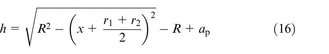
The grinding depth of any grinding point was obtained by the geometric relationship as equation (16)
The area A of grinding contact area is shown in (17)
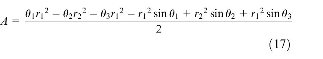
Where
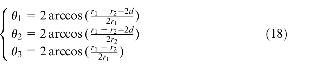
The heat distribution ratio of any grinding point is approximately the heat distribution ratio of a single abrasive particle. Using the traditional heat distribution ratio model,22–24 the heat distribution ratio between the cup wheel and the workpiece at any grinding point is shown in (19)
Where ks is the thermal conductivity of the grinding wheel; kw is the thermal conductivity of GFRP; r0 is the effective contact radius of the abrasive particles.
The homogeneous treatment of GFRP in the thermal analysis of workpiece materials,25,26 and the material properties are defined as equation (20)
Where φf is the volume ratio of glass fiber; ρf is the density of glass fiber; ρe is the density of epoxy resin; cf is the specific heat capacity of glass fiber; ce is the specific heat capacity of epoxy resin.
In summary, the heat flux density distribution function of the incoming workpiece in the grinding contact area is shown in equation (21)
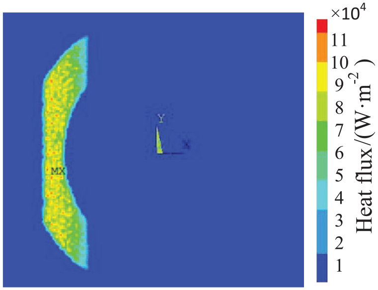
Relevant grinding parameters were taken into equation (21), and the heat flux distribution function was numerically solved by MATLAB. When the wheel speed is 8000 r/min, feed rate is 0.02 m/s and grinding depth is 60 µm, the heat flux distribution image was shown in Figure 3.
Image of heat flux distribution.
Finite element simulation of grinding temperature field
The finite element software ANSYS was used to analyze the three-dimensional transient heat transfer of the grinding temperature field. In the local grinding process of wind turbine blade, the workpiece has a large curvature radius, and the curved surface was simplified to an ideal plane, which can effectively reduce the difficulty of simulation of the grinding temperature field. The material composition of the wind turbine blade is relatively complex. In the simulation process, the material properties are simplified. It was assumed that the workpiece material is isotropic, and the thermal conductivity change caused by the temperature change of the workpiece material is ignored.
Material properties of cup wheel and wind turbine blade
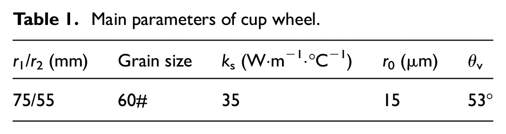
The main parameters of alumina cup wheel are shown in Table 1.
Main parameters of cup wheel.
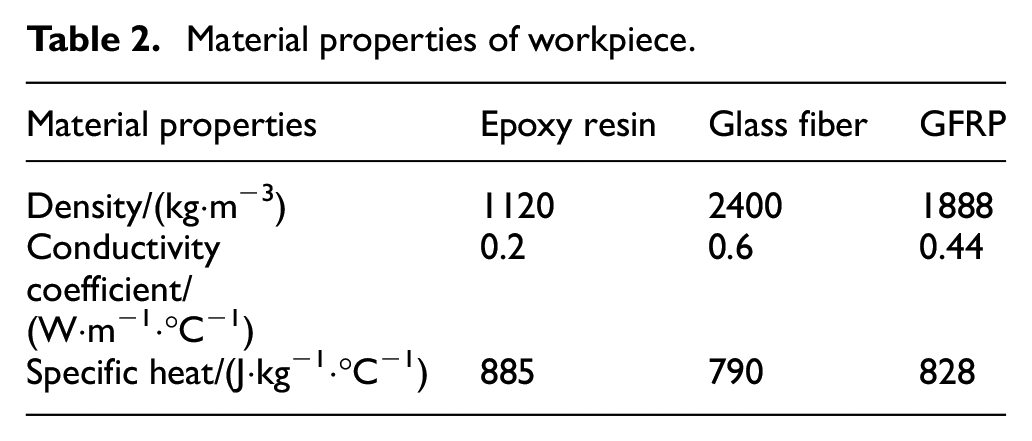
The length, width and thickness of the simulation workpiece are 200 mm, 100 mm, and 15 mm, respectively. The Brinell Hardness of GFRP is 140 HB. GFRP is composed of glass fiber and epoxy resin, glass fiber volume ratio φf is 0.6. According to equation (20), the properties of GFRP materials are homogenized, and the material properties of the workpiece are shown in Table 2.
Material properties of workpiece.
Condition of finite element simulation
The simulation environment temperature was set to 20°C. According to the GFRP surface grinding experiment, the wear coefficient kapr between the alumina cup wheel with particle size of 60# and the workpiece was about 0.03. The 3D model of GFRP workpiece was established, and tetrahedral mesh was used to divide the workpiece, the maximum side length of tetrahedral mesh was 0.004 m. The temperature gradient of the grinding surface of the workpiece is large, so the grid of the grinding surface was refined, and the grid below the grinding surface was thickened, the meshing is shown in Figure 4. Under the condition of ensuring the calculation accuracy, dividing the grid in this way can effectively shorten the simulation time.
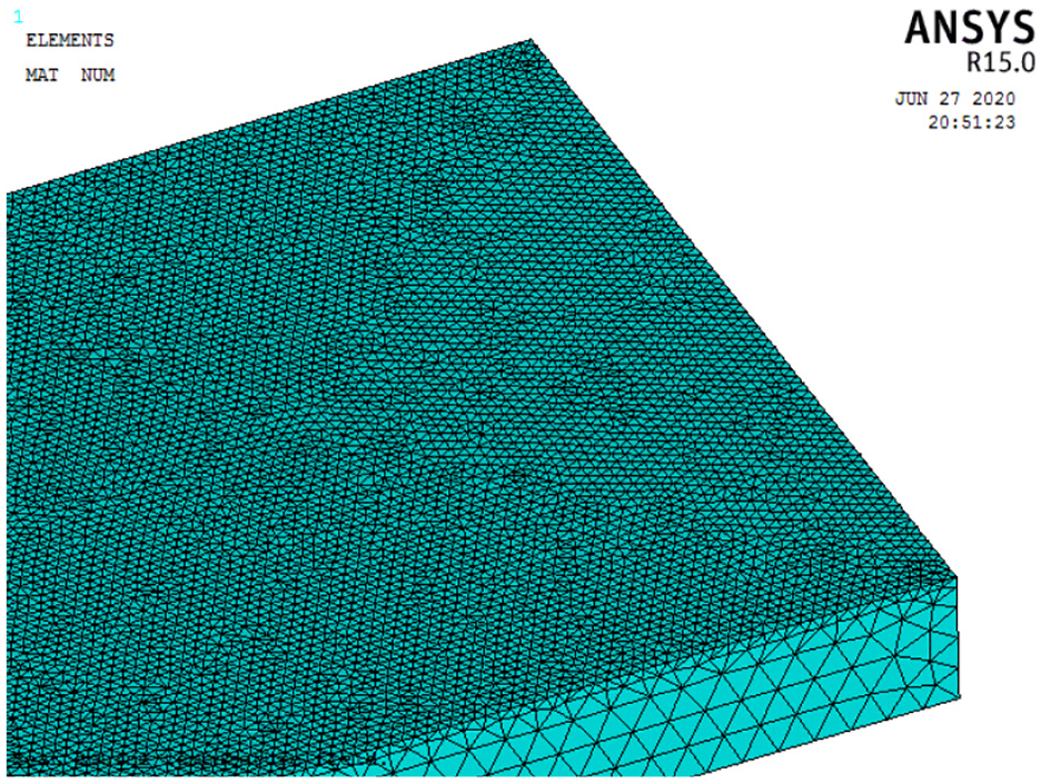
Mesh diving.
Bring the related parameters into the heat flux density distribution function, and define the heat flux density distribution function and boundary conditions in the ANSYS classic interface. The simulation time was set to be 15 s, and the convective heat transfer coefficient between the workpiece and the air contact surface was 12.5 W/(m2·°C). The continuous grinding process was divided into multiple load steps through the APDL program, and the heat source was moved to form the grinding temperature field through cyclic iteration. When the wheel speed is 8000 r/min, feed rate is 0.02 m/s and grinding depth is 60 µm, the heat source image of single load step is shown in Figure 5.
Heat source of single load.
Experimental verification
Experimental conditions
Experimental platform is shown in Figure 6. The grinding robot is an EFORT 6 degrees of freedom industrial robot, the model is ER20-C10, and the repeated positioning accuracy is ±0.06 mm. Workpiece for wind turbine blade root intercept part, its curvature radius is 1m. In the process of curved surface grinding, the direction of the total normal grinding force coincides with the normal vector of the wind turbine blade. It is difficult for the three component dynamometer to directly measure the total normal grinding force, while the total tangential grinding force always faces one side of the cup wheel. Therefore, the total normal grinding force was obtained by measuring the total tangential grinding force. The model of three component dynamometer is Kistler 9257B, the model of charge amplifier is 5080A and the model of data acquisition card is 5697A1. During the grinding process, the flexible grinding device was used to adjust the total method to indirectly guarantee the grinding depth to the grinding force, and the intelligent digital display instrument shows the output force of the flexible grinding device in real time.
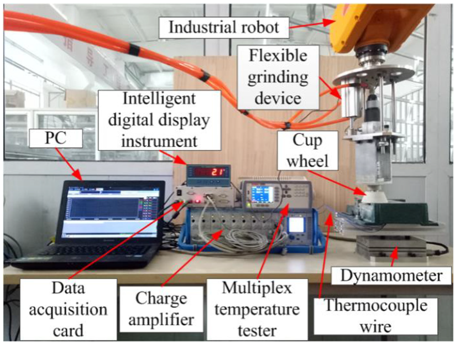
Platform of experimental.
Artificial thermocouple was used to measure the temperature at a specific point of grinding surface, the distribution of thermocouple nodes as shown in Figure 7, the model of the thermocouple is type K. The multi-channel temperature tester transmits the temperature signal of the thermocouple to the computer. The model of the multi-channel temperature tester is AT4508 with the resolution of 0.1°C.
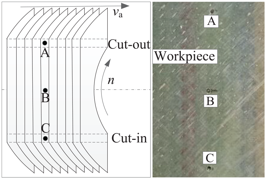
Distribution of thermocouple nodes.
Grinding process parameters
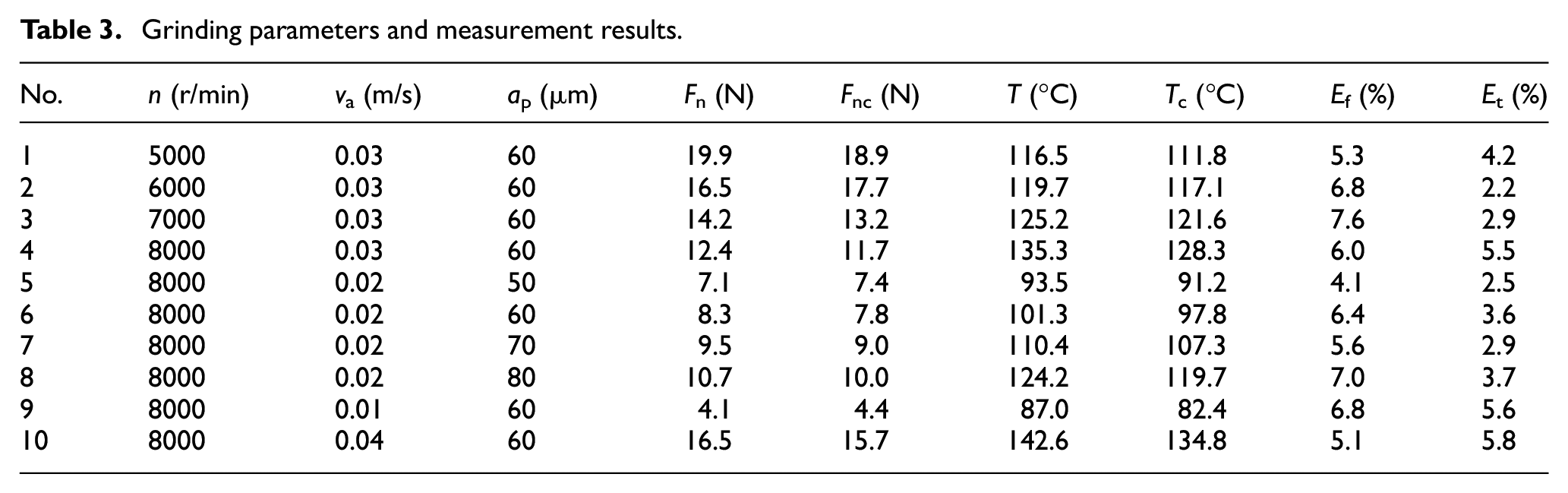
Surface grinding experiments were carried out by single factor method. The experimental variables are wheel speed, feed rate and maximum grinding depth. Fnc is experimental measurement results of total normal grinding force, T is maximum grinding temperature simulated by finite element, and Tc is maximum grinding temperature measured by artificial thermocouple, Ef is relative error of the total normal grinding force, Et is relative error of the maximum grinding temperature. Specific grinding parameters and measurement results are shown in Table 3.
Grinding parameters and measurement results.
Comparative analysis of simulation and experiment
Figure 8 is the bar chart comparing the numerical calculation results of the total normal grinding force with the experimental values. The numerical results are in good agreement with the experimental values and the maximum relative error is <8%. According to analysis of the error reasons, the selected wear coefficient and the workpiece material performance parameters are all constant values, and these parameters are floating due to the increase of grinding temperature. In addition, the grinding performance of the cup wheel will be reduced due to the passivation of grinding particles after a long time of grinding and the fact that the composite grinding debris is easy to adhere to the grinding surface of the cup wheel at high temperature.
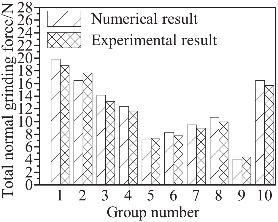
Comparison of calculated values and experimental values for total normal grinding force.
When the wheel speed is 8000 r/min, feed rate is 0.02 m/s and grinding depth is 60 µm, Simulation results of temperature field at different times are shown in Figure 9. As can be seen from the Figure 9, with the increase of grinding time, the grinding temperature gradually stabilizes. In addition, the maximum grinding temperature is mainly concentrated in the same position on both sides of the grinding contact area. The grinding temperature on both sides is basically the same, and significantly higher than the intermediate temperature.
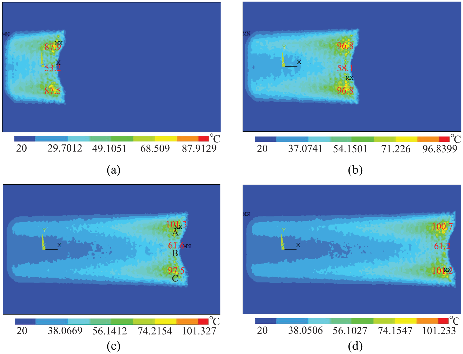
Simulation image of temperature field: (a) t = 4 s, (b) t = 6.6 s, (c) t = 8 s, and (d) t = 9 s.
The reason why the grinding temperature on both sides is higher than the other positions is that the cumulative grinding time on both sides is greater than the other positions. For example, when the grinding surface is the entire ring, the movement of the ring is overlapped by MATLAB programming, As shown in Figure 10. There are many overlapping parts on both sides, and the cumulative grinding time is relatively longer in the middle, resulting in higher temperatures on both sides.
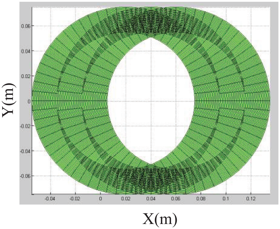
Schematic of overlapping circles.
Under the above conditions, the temperature change curves at specific points of simulation and experiment are shown in Figure 11. The results of simulation and experiment show that the maximum grinding temperature at points A and C is obviously higher than that at point B, because the cumulative grinding time at points A and C is greater than that at point B. In addition, the temperature difference between simulation A and C is small, while the temperature at point C in the experiment is greater than that at point A and the temperature difference is large. It can be seen that the maximum grinding temperature in the actual grinding process occurs on the cut-out side of the cup wheel. The reason for the analysis is that there is heat accumulation from the cut-in point to the cut-out point of the cup wheel, resulting in a higher temperature on the cut-out side.
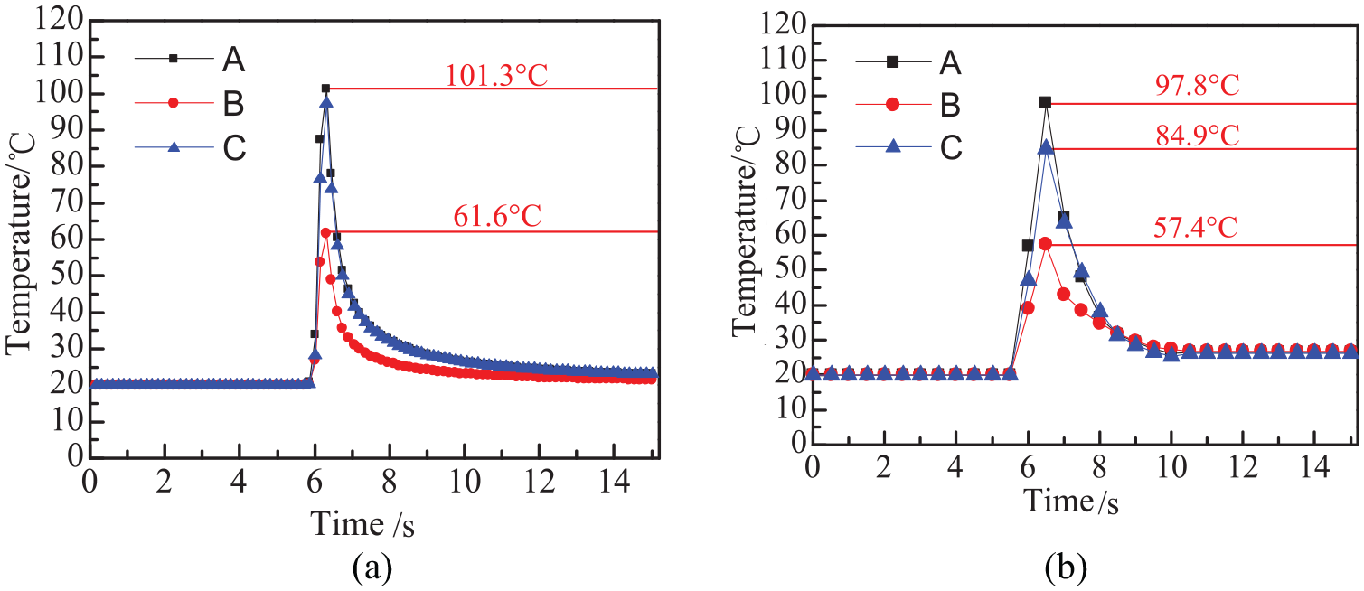
Comparison of simulation and experimental for grinding temperature: (a) temperature change curve of simulation and (b) temperature change curve of experimental.
Figure 12 is the bar chart comparing the maximum grinding temperature measured by finite element simulation and experiment under different grinding process parameters. It can be concluded from the Figure 12 that the maximum grinding temperature of the experiment is basically the same as that of the simulation, but the experimental value is slightly less than the simulation value, and the maximum relative error between the simulation and the experiment is <6%. The reason for the error is that there is a certain distance between the thermocouple node and the grinding contact surface, which causes the measured temperature to be lower than the actual grinding temperature of the grinding surface. The error is within the allowable range, which can verify the theoretical model to some extent.
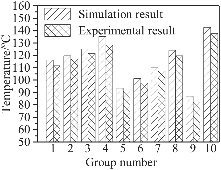
Comparison of predicted and experimental values for maximum grinding temperature.
Figure 13 shows the variation trend of the maximum grinding temperature in simulation and experiment with the wheel speed. It can be seen from the Figure 13 that the maximum grinding temperature increases with the wheel speed. The increase of wheel speed will significantly increase the grinding power at any grinding point and thus cause the temperature to rise. In addition, according to the expression of heat distribution ratio (19), the increase of wheel speed will also cause the heat distribution ratio to increase, resulting in an increase in the incoming heat of the workpiece.
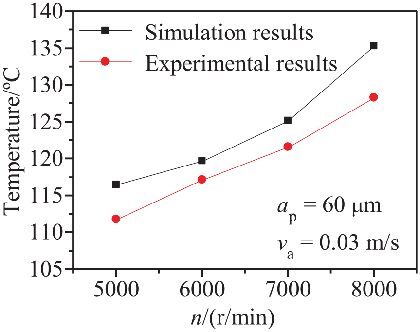
The maximum grinding temperature varies with the n.
Figure 14 shows the variation trend of maximum grinding temperature with maximum grinding depth in simulation and experiment. As the maximum grinding depth increases, the maximum grinding temperature increases. The reason for this trend is that the maximum grinding depth is mainly indirectly controlled by the total normal grinding force adjusted by the flexible grinding device. With the increase of the maximum grinding depth, the corresponding total normal grinding force will increase. When other grinding conditions remain unchanged, the grinding power at any grinding point in the grinding contact area will increase, and the grinding temperature will increase significantly.
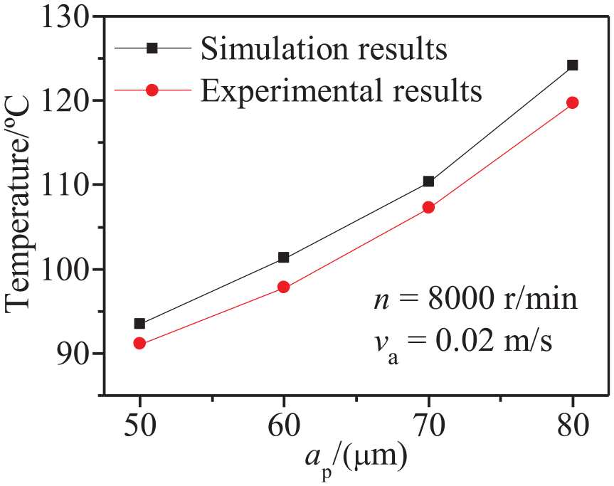
The maximum grinding temperature varies with the ap.
Figure 15 shows the variation trend of maximum grinding temperature with feed rate in simulation and experiment. The maximum grinding temperature increases with the increase of feed rate. The reason is that, when the feed rate increases, the material rate removed per unit time increases, the abrasive cutting produces a lot of heat, resulting in a rapid rise in grinding temperature. In addition, with the increasing of the feed rate, the rising trend of the maximum grinding temperature gradually slows down. The reason is that the continuous increase of feed rate leads to a shorter grinding stay time at any position of the grinding surface, resulting in a reduction in the instantaneous heat transferred into the wind turbine blade during the grinding process. By comparing the variation trend of feed rate to the maximum grinding temperature with the variation trend of wheel speed and maximum grinding depth to the maximum grinding temperature, it can be found that the rising trend of the maximum grinding temperature caused by feed rate is obviously greater than that caused by the wheel speed and maximum grinding depth to the maximum grinding temperature. The analysis shows that the increase of wheel speed and maximum grinding depth is only the increase of material removal efficiency per unit time, the total normal force required in high speed grinding will not increase significantly, and the increase of feeding rate will increase the resistance of the whole cup wheel in the feeding direction. Under the condition of a certain wheel speed, the corresponding total normal grinding force also needs to increase greatly to improve the material removal rate. Therefore, the rising trend of temperature is more obvious. Contrast grinding machine adopts cup wheel surface grinding temperature changing trend with feed rate, the influence of its feed rate on temperature rising trend is smaller than the influence of wheel speed and grinding depth. This change trend is quite different from the change trend of the grinding temperature of the robot using flexible grinding device. The reason is that the cup wheel of the grinding machine directly controls the grinding depth. Although the feed rate increases during the grinding process, the material removal of the cup wheel grinding surface can timely eliminate the normal grinding force inside the grinding contact surface, and the normal grinding force has little influence on the grinding temperature. However, the robotic grinding indirectly guarantees the grinding depth through flexible grinding device. As the feed rate increases, the normal grinding force controlled by the flexible grinding device will also increase, causing the increase in grinding temperature to become more apparent.
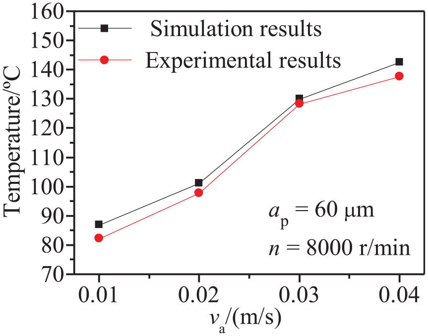
The maximum grinding temperature varies with the va.
Conclusion
According to the relationship between the total normal grinding force and the maximum grinding depth, a grinding force model was established for the robot grinding wind turbine blade. The maximum relative error between the calculated results and the experimental results is less than 8%. This grinding force model provides reference for robot grinding large curved surface force-position hybrid control.
According to the normal grinding force distribution and grinding process parameters in curved surface grinding contact area, the curved surface heat source model was established, and the temperature field under different grinding process parameters was simulated by finite element method. The simulation and experimental results show that the high grinding temperature is mainly concentrated in the grinding contact area, the temperature on both sides of the contact area is higher than the intermediate temperature, and the highest grinding temperature appears on the cut-out side of the cup wheel.
By analyzing the influence trend of different grinding process parameters on the maximum grinding temperature, it can be seen that the maximum grinding temperature increases with the increase of wheel speed, feed rate and maximum grinding depth respectively, and the feed rate has the greatest influence on the grinding temperature. The maximum relative error between the simulation results and the experimental results is <6%, which indicates that the method can accurately predict the temperature distribution of robot grinding wind turbine blade and the maximum grinding temperature with the change of grinding parameters.
Footnotes
Appendix 1
Declaration of conflicting interests
The author(s) declared no potential conflicts of interest with respect to the research, authorship, and/or publication of this article.
Funding
The author(s) disclosed receipt of the following financial support for the research, authorship, and/or publication of this article: This work was supported by the Natural Science Foundation of Hebei Province (F2017202243, E2019202132, E2019202169); Colleges and Universities in Hebei Province Science and Technology Research Project (BJ2019049); Natural Science Foundation of Tianjin City (18JCTPJC54700); China Postdoctoral Science Foundation (2018 M641616).