
Abstract
A new finishing technique called ultrasonic-assisted magnetic abrasive finishing integrates ultrasonic vibration with magnetic abrasive finishing process for finishing of workpiece surface more efficiently as compared to magnetic abrasive finishing in the nanometer range. During finishing, two types of forces are generated in ultrasonic-assisted magnetic abrasive finishing, namely, a normal force (indentation force) and a tangential force (cutting force) that produces a torque. The finishing forces have direct control on the rate of change of surface roughness and material removal rate of the workpiece surface. This article deals with the theoretical modeling of the normal force and the finishing torque based on the process physics. In this work, finite element simulations of the electromagnet were performed to calculate a magnetic flux density in the working zone; they were also used to evaluate the normal force on the workpiece surface. The theory of friction for the abrasion of metals was applied together with the effect of ultrasonic vibration to calculate the finishing torque. The developed model predicts the normal force and finishing torque in ultrasonic-assisted magnetic abrasive finishing as functions of the supply voltage, working gap and concentration of abrasive particles in a flexible magnetic abrasive brush. A comparison of theoretical and experimental results is performed to validate the proposed model.
Keywords
Introduction
With present technological advancements, there is a great need for a wide range of industries to have fine finishing capabilities which can produce surface roughness in nanometer range. There were many developments over the last few decades in the cost-effective and quality-assured manufacturing of precisely finished components for a variety of industrial applications.1,2 There are a number of finishing processes involving the use of abrasives, for example, abrasive flow machining,3–5 magneto-rheological fluid-based machining6,7 and magnetic abrasive finishing (MAF). 8 In MAF, the finishing forces are primarily controlled by the magnetic field produced by a permanent magnet or an electromagnet. 9 The MAF process gained popularity in the industrial application as it can be used for finishing of both ferromagnetic and non-ferromagnetic materials. In this process, a flexible magnetic abrasive brush (FMAB) is formed that finishes the surface. The process has several advantages over bonded abrasive processes such as grinding. Some of these are self-adaptability of finishing tool, self-sharpening of abrasives and no requirement of dressing.1,10,11 However, it was found that MAF was less efficient with regard to the rate of improvement in the surface finish when used for finishing of materials with high hardness values.12,13 Many variants of MAF were developed to reduce this shortcoming and also to enhance the process capabilities; ultrasonic-assisted magnetic abrasive finishing (UAMAF) process is one such development in this direction. 14
UAMAF is a hybrid finishing process in which ultrasonic vibration is introduced into a finishing zone of the MAF process to obtain improved surface topology within a reasonably short period of time. It was found experimentally that the UAMAF process provided better performance than a conventional MAF process. UAMAF could produce a finished surface with roughness value of 22 nm using unbonded or loose magnetic abrasive particles (UMAPs) with AISI 52100 as the workpiece material.
15
A schematic of the UAMAF setup is shown in Figure 1. The electromagnet had four poles alternately arranged as north and south poles, and ultrasonic vibration was applied to the workpiece fixture by a horn attached to a transducer. The workpiece fixture was mounted on a dynamometer assembly to monitor the magnitude of finishing forces and torque during experimentation. In UAMAF, nano-scratching and micro-chipping by abrasive particles, additionally enhanced due to ultrasonic vibrations, were responsible for material removal from the workpiece surface.
16
Forces encountered during the finishing had a direct influence on quality and exactitude of the finished surface. Hence, it is imperative to have an in-depth understanding of the forces involved in UAMAF. Finishing forces in UAMAF were induced as a result of the interaction of FMAB with the workpiece surface in the presence of ultrasonic vibration. The strength of the FMAB depended upon the magnetic field produced by the electromagnet, a higher strength of FMAB resulting in a higher finishing force during the process. There were two main finishing forces during UAMAF process, namely, a normal force and a tangential force. The normal force
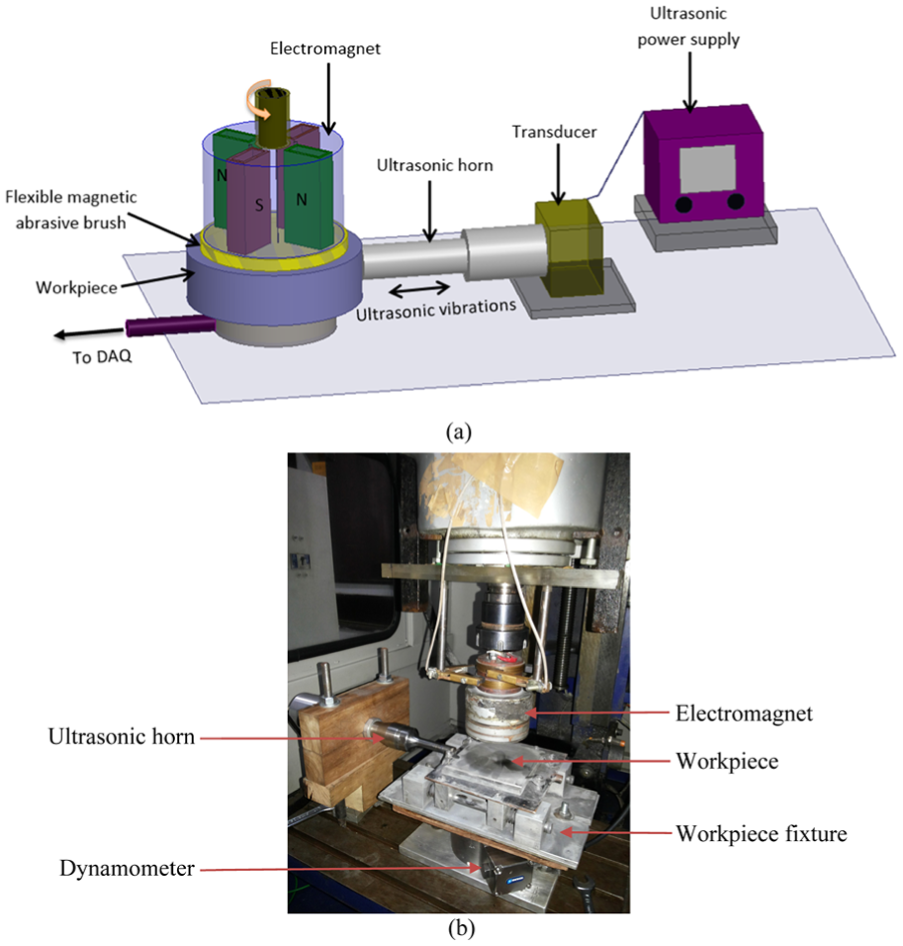
Experimental setup used to estimate normal force and finishing torque during UAMAF: (a) schematic diagram and (b) actual system.
The first successful attempt to model an MAF process was made by Shinmura et al. 17 They developed equations for finishing forces on a cylindrical workpiece and estimated the magnetic pressure created by abrasive particles on the workpiece surface. Their model provided the good qualitative agreement with the experiments. Another model for the evaluation of magnetic finishing pressure on the workpiece surface was developed by Khairy. 18 He modeled kinematics of the MAF process analytically by considering similarities of the cutting zone of belt or form grinding with that of MAF and validated the model with experiments on steel bars. Mori et al. 19 explained the formation of the FMAB from the standpoint of brush formation energy considering varying weights of magnetic abrasive particles. The mechanism of MAF was described on the basis of normal and tangential forces acting on the edges of FMAB. The calculated values of normal force agreed well with the measured ones.
A theoretical model to estimate the finishing pressure, surface roughness and finishing time for a tool–workpiece interaction in a cylindrical MAF process was estimated by Kim and Choi. 20 They deduced that the strength of magnetic flux density in the working gap was greatly affected by the magnitude of the gap. A finite element analysis (FEA) of magnetic field for the prediction of magnetic potential in the working gap was carried out by Jayswal et al. 21 to calculate normal and tangential forces in the case of the MAF process. They also discussed different conditions of the finishing forces for the removal of material from the workpiece. Kala et al. 22 modeled normal and tangential forces in double-disk MAF process considering the analogy of a string fixed at two ends under tension. The equations of Lorentz force and the Ampere’s law were used to calculate the forces. They used experimental data to incorporate the effect of magnetic flux density and angle of inclination of FMAB chains. The model was validated using experimental results.
The literature survey indicates that attempts17–22 were made to predict the finishing forces during MAF. First attempt to model UAMAF process was made by Mulik and Pandey. 23 They developed a model for the prediction of finishing force and torque as functions of the supplied voltage, working gap and hardness of the workpiece surface. They assumed abrasive grains of a tetrahedral shape and tangential force exerted by the indented part of grains as a shear force on the workpiece material. The effect of ultrasonic vibration on the finishing torque was calculated based on its impulse. The developed model of normal force and finishing torque was in good agreement with the experimental results.
In this work, an improved model of UAMAF for the estimation of finishing force and torque was developed. The novelty of this model compared to existing model is as follows:
The average magnetic flux density on the surface of the workpiece is obtained by finite element simulation.
A body-centered cubic (BCC) structure is assumed for the arrangement of ferromagnetic and abrasive particles throughout the working gap.
The effect of ultrasonic vibration on the finishing torque is assessed by considering the relative velocity of abrasive particles and the workpiece surface, unlike considering only the impulse of vibration to incorporate its effect.
The theory of abrasion in metal is used for the calculation of friction between the FMAB and the workpiece surface.
The developed model was used to predict the normal force and finishing torque considering the voltage, working gap and concentration of abrasives as significant parameters. It was validated with the experiments.
Modeling of finishing force and torque
The mechanism for the formation of the FMAB and its interaction with the workpiece surface is a complex system; hence, to simplify the mathematical modeling of the finishing force and torque, the following realistic assumptions are made:
All the ferromagnetic and abrasive particles are considered spherical in shape. Although these particles are of varied shape due to the differences in their corresponding manufacturing methods, this assumption saves the modeling effort substantially and relinquishes the problem of obtaining a large amount of data regarding the shape of the particles, since particles can be characterized by a unique parameter, that is, the grain diameter. 24 Also, the orientation of active abrasive grains on the surface of the workpiece is rendered inconsequential.
The size of ferromagnetic and abrasive particles depends on their mesh or sieve number and remains uniform throughout the FMAB. The diameter of abrasive
The ferromagnetic chains formed are continuous and remain unaffected by the presence of non-magnetic abrasive particles and rotation of the electromagnet.
A magnetic flux density is uniformly distributed over the workpiece surface and also does not vary with time. Its magnitude, for theoretical calculations, is the average of values obtained from simulations at different locations on the surface of the workpiece under the FMAB.
The properties of UMAPs do not change during the process. As UAMAF has a low material removal rate, the removed material mixed with UMAPs does not significantly alter properties of the FMAB.
Only a fraction of the abrasive particles that are in contact with the workpiece surface takes part in cutting action, and those particles are known as active abrasive particles.
The FMAB consists of abrasive and ferromagnetic particles without voids.
Finite element simulation of magnetic field
Distribution of the magnetic field in the finishing zone significantly affects the finishing characteristics of the process.
20
Its distribution in the machining gap determines the configuration and rigidity of the FMAB for the finishing operation.
25
The magnetic field distribution in the working gap includes the magnitude of magnetic flux density as well as its gradient. It depends on the shape, size, the material of the magnetic poles, supplied voltage (or current) to the coils of the electromagnet and the relative position of magnetic poles with regard to the workpiece. Indentation of an active abrasive particle into the workpiece surface is due to the normal force applied to it by surrounding magnetized ferromagnetic particles as a result of the magnetic levitation force.
6
All the above factors are important to calculate the magnetic force acting on active abrasive particles, producing finishing pressure on the surface of the workpiece during UAMAF. When a voltage (or current) is applied to the electromagnet, a magnetic field is created in the working gap. Higher the magnetic flux density, the higher is the strength of the FMAB and the higher are the forces acting during the interaction of FMAB and surface of the workpiece. To determine the magnetic flux density
A computer-aided design (CAD) model of electromagnet was developed (refer Figure 1) in the software. The length and cross section of the magnet were 55 mm and 25 mm × 15 mm, respectively, with the diameter of the magnet core as 80 mm. The relative permeability of the core (iron) was 4000, conductivity of coils (copper) 58 × 106 S/m and the relative magnetic permeability of working gap (air) was 1. Different excitations in the range of 20–100 V were applied to the coils of the electromagnet to get the magnetic flux density on the surface of the workpiece considering different working gaps in the range of 1–2.5 mm. The element used in numerical simulations was a tetrahedron with the field approximated over it as a second-order basis function to account for geometrical complexities and also to improve the accuracy of the solution. The final solution was obtained using an iterative solution method, with an initial mesh generated based on a surface approximation and further refinement of mesh occurring in regions with an error in energy norm higher than 1%. The value of error in the energy norm was computed after each solution step and used as a measure of convergence for the refined mesh. The total of 20 iterative steps was performed to get the final solution. In total, 192,189 tetrahedral elements were created in the final step.
A contour plot of magnetic flux density on the surface of the workpiece and magnetic lines of forces created in the working gap as observed in the final step of simulations are depicted in Figure 2(a). From Figure 2(a), it can be seen that the magnetic flux density was higher under the poles than elsewhere and has similar variation under every pole. A surface plot under the magnetic pole (Figure 2(b)) is drawn from the simulation data in order to conceptualize correct variation of magnetic flux density. The magnetic flux distribution was observed to have different magnitudes varying with the location under the pole. Hence, for calculation of the average magnetic flux density, the magnitude of magnetic flux density was considered at the interval of 1 mm throughout the rectangular area of the slot, and its average value was calculated.
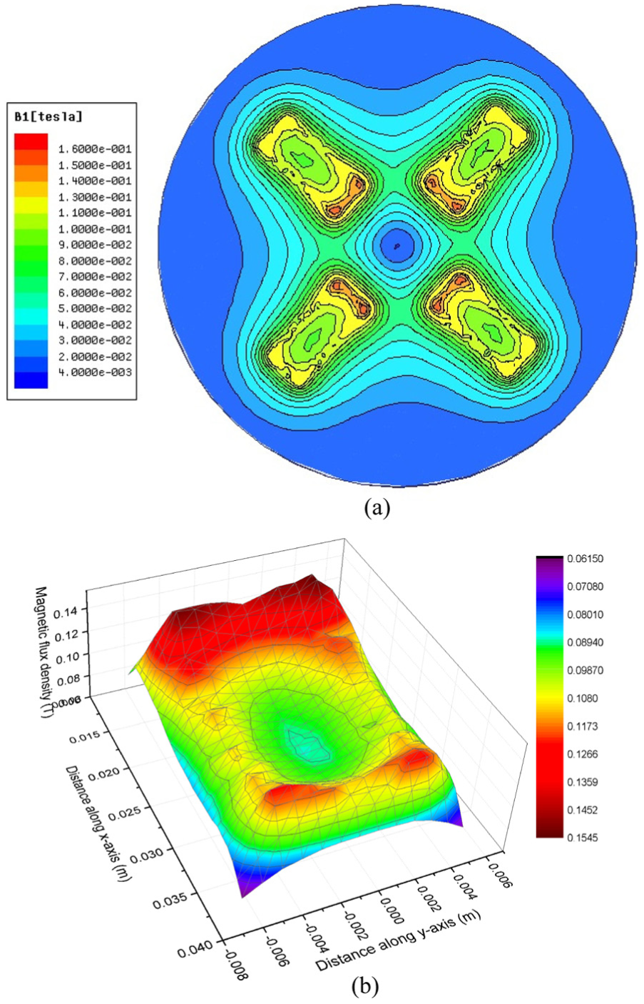
(a) Contour plot of magnetic flux distribution on surface of workpiece and (b) surface plot of magnetic flux density under one pole.
Number of active abrasive particles
The normal force acting on abrasive particles will force them to indent on to the workpiece surface, and the relative motion (due to tangential force) between these abrasive particles and workpiece surface will shear off the material in front of the indented portion of the abrasive particle as micro/nano-scratching. Only a few abrasive particles come in contact with the workpiece surface and actually take part in the finishing action; these are known as “active abrasive particles”. Hence, for the development of any theoretical model for calculation of forces, material removal or surface roughness in UAMAF, the assessment of active abrasive particles is a necessary step. UMAPs are a blend of ferromagnetic and abrasive particles. In UMAPs, abrasive and ferromagnetic particles are randomly arranged. When the magnetic field is activated, the ferromagnetic particles in UMAPs orient themselves in the form of chains along the magnetic lines of force. The chains are formed as a result of interaction between the magnetic dipoles of ferromagnetic particles due to the application of magnetic field. 26 The stable brush forms only when the magnetic energy required for its formation is the minimum; 19 the minimum value of dipolar energy occurs when dipoles join each other and align along the direction of field forming the chains of ferromagnetic particles. 27 The abrasive particles of non-magnetic nature get entrapped between these chains of ferromagnetic particles thus forming the FMAB (Figure 3(a)). The magnetic energy present in the FMAB is used to grip non-magnetic abrasive particles; at the equilibrium condition, the FMAB also attains the minimum energy. 19 Due to the presence of non-magnetic abrasive particles, chains are hardly continuous and form a complex structure combining ferromagnetic and abrasive particles. Considering, these facts and to simplify the analysis, it was assumed that an abrasive particle in combination with eight ferromagnetic particles forms a BCC structure with ferromagnetic particles at eight corners of the cube and the abrasive particle remaining at its center 28 as shown in Figure 3(b). Hence, a uniformity throughout the FMAB can be observed. Assuming BCC structure implies that abrasive particle is rigidly entrapped between the ferromagnetic particles and no relative motion between them is possible since ferromagnetic particles attain the position along the magnetic lines of forces. It also implies that the force from any direction (horizontal or vertical) that acts on ferromagnetic particles is completely transmitted to the adjacent abrasive particle. Due to large number of random abrasive and ferromagnetic particles, the above assumptions may be reasonable. It was also assumed that this unit of BCC cells was uniformly distributed throughout the workpiece surface.
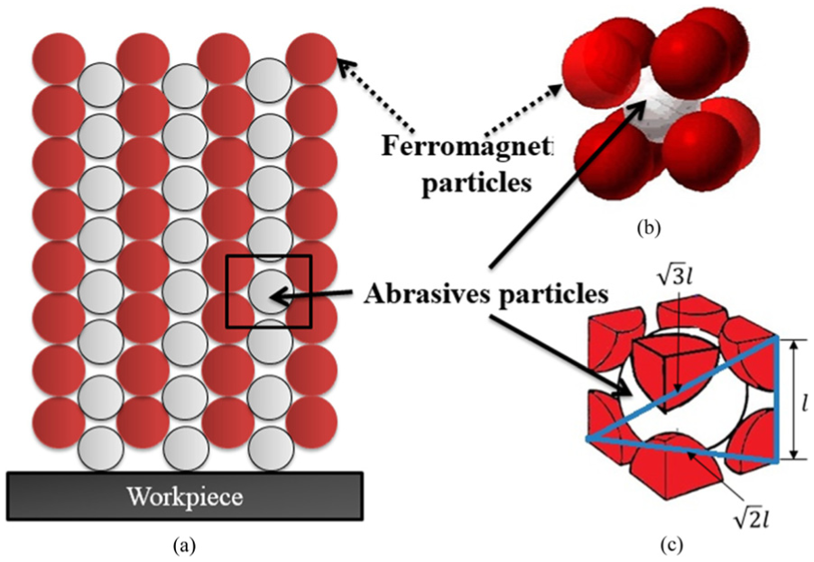
(a) Schematic of two-dimensional arrangement of chains comprising ferromagnetic and abrasive particles on enactment of magnetic field, (b) an arrangement of abrasive and ferromagnetic particles in 3D BCC structure and (c) BCC unit cell considered for modeling.
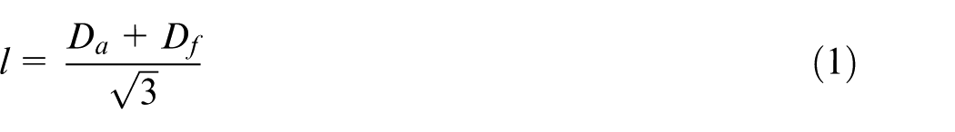
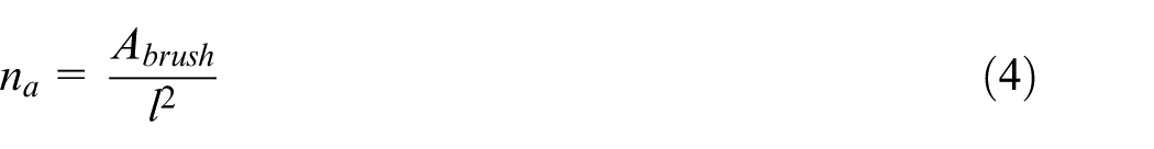
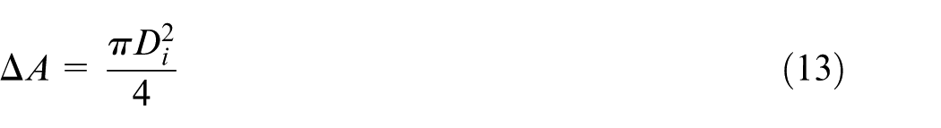
As shown in Figure 3(c), one BCC unit has one abrasive grain in it. The total number of BCC units on the surface of the workpiece is the ratio of area of the brush in contact with the surface of workpiece to the area of the face of one BCC unit, which depends on the size of ferromagnetic and abrasive particles. The length of the unit BCC cell
The area of the brush
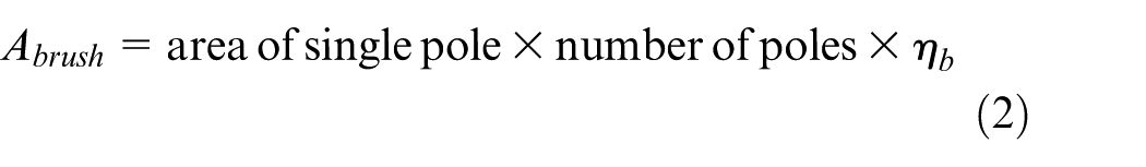
where
Here, for simplicity,
Volume fraction of ferromagnetic particles
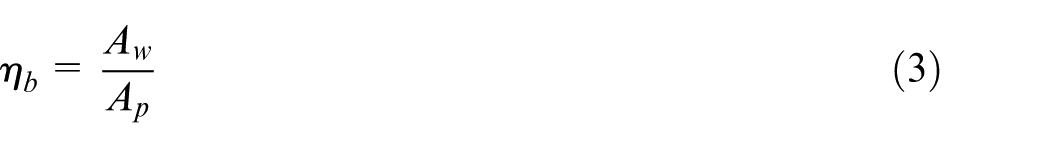
The volume fraction of ferromagnetic particles can be calculated from the weight fraction of abrasive particles (or concentration) C as follows. The density of the brush
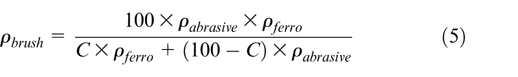
where
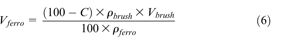
where

Hence, from equations (5)–(7), the volume fraction of ferromagnetic particles
Calculation of average normal force
The magnetic flux density calculated in section “Finite element simulation of magnetic field” on the surface of the workpiece was used to estimate pressure on this surface. The average normal pressure
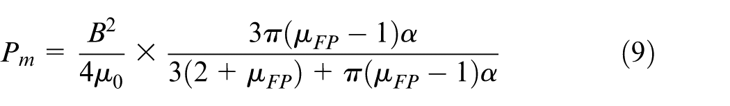
where

Thus, the average normal force by a single abrasive particle
Calculation of average finishing torque
The normal force calculated in section “Calculation of average normal force” developed due to the magnetic field acting on abrasive particles results in their indentation into the workpiece surface. The relative motion between the indented abrasive particles and workpiece surface causes a resisting force tangential to the surface. To overcome this resisting force, a torque has to be provided to the electromagnet, which is called finishing torque. The cross-sectional view of an indented active abrasive particle into the workpiece surface is shown in Figure 4. The extent of indentation of abrasive particles depends upon the magnitude of the normal force and hardness of the workpiece material. 27 When the tangential force is applied to abrasive particles, due to rotation of the electromagnet, the workpiece material in front of the indented portion resists the motion of abrasive. This resistance depends directly on the magnitude of the normal force (or indentation force). When the tangential force is sufficient to overcome this resistance, the abrasive plows the material in front of it causing abrasion of the workpiece on its surface. Bowden et al. 29 stated that the frictional force was not only a surface effect but also depended upon the bulk properties of sliding bodies. They described that the frictional resistance between the sliding bodies was essentially caused by the shearing of metallic junctions formed due to adhesion or welding at contact points and also due to the resistance force of plowing of the surface irregularities of the softer metal by the harder one.
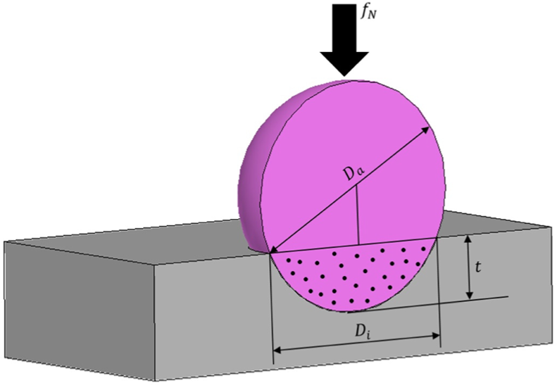
Schematic of cross-sectional view of an active abrasive particle indented into surface of workpiece.
When an indented active abrasive particle is provided a relative motion tangential to the workpiece surface, plowing and adhesion phenomena cause friction between the abrasive and the workpiece. The coefficient of friction depends on the shape and size of the abrasive particle. 30 Here, it is assumed that the frictional force acting between the FMAB and the workpiece surface is caused by plowing and adhesion. The friction force during the interaction of the FMAB and the workpiece surface is derived below. The force on single abrasive particle is given by 31

where
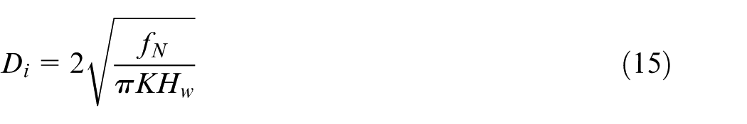
where

Here, K = 1 for brittle material and K > 1 for ductile material (for steel K = 3.0). Hence, from equations (12)–(14), the diameter of indentation by the abrasive particle into the workpiece surface can be calculated as
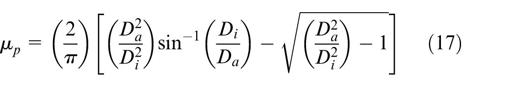
The coefficient of friction due to plowing and adhesion of a sphere on a flat surface is

Here,
and the latter is 30
Here,

The torque

Here,
where
Effect of ultrasonic vibrations on finishing torque
In UAMAF, the FMAB rotates with a constant angular speed about Z-axis, and a vibratory motion with amplitude
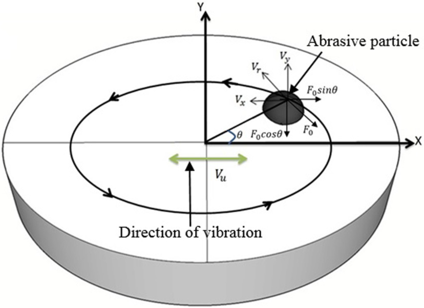
Schematic of track of indented active abrasive particle and components of rotational velocity and friction force.
The magnitude of total friction force
Case 1: component of velocity along direction of ultrasonic vibration
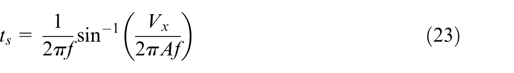
The instantaneous velocity of ultrasonic vibration, that is, of the workpiece surface, is assumed to be given by the equation

where
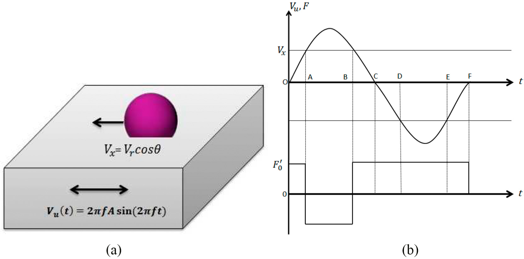
(a) Sliding of abrasive over workpiece surface with vibratory motion collinear with sliding velocity direction and (b) variation of instantaneous vibrational velocity of workpiece with time and corresponding change in friction force direction between abrasive and workpiece.
The workpiece velocity
The resultant averaged friction force
where
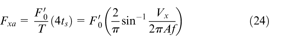
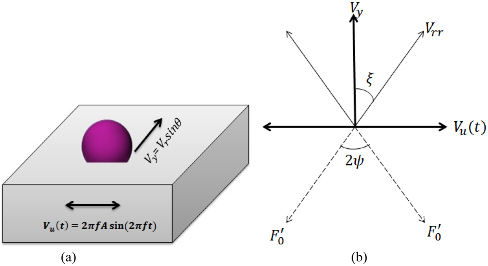
Case 2: component of velocity perpendicular to direction of ultrasonic vibration
In Figure 7(b),
(a) Sliding of abrasive over workpiece surface with a vibratory motion perpendicular to sliding velocity direction and (b) relationship between vibrational velocity, sliding velocity, resultant velocity and direction of friction force, changing along angle
If, at any instant,
In the direction of the velocity component
In the direction perpendicular to
From Figure 7(b),
The instantaneous velocity of vibration vanishes at the phase angles
The average friction force over the complete time period for one cycle of vibration
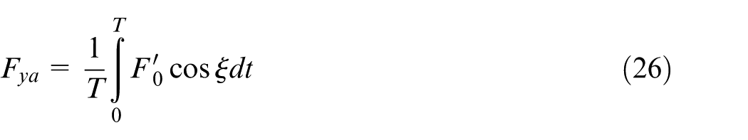
From equations (25) and (22)
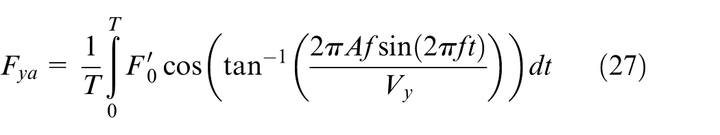
Considering, the phase angle for the vibration cycle as
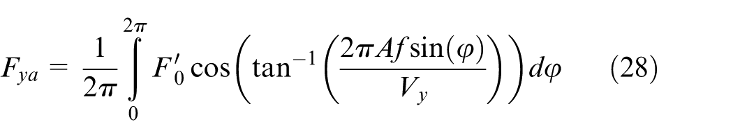
The above equation was computed numerically to get the averaged value of the friction force along the direction of
The values of the average frictional force were computed in both the cases for a single cycle of vibration; a similar cycle is repeated over the whole finishing time. It is assumed that the force calculated for one cycle of vibration will remain constant. Hence, total average frictional force considering the effect of ultrasonic vibration is computed as
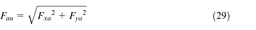
To calculate the above equation, forces

This torque
Experimentation
The experimental setup used to measure finishing forces for the case of UAMAF is shown in Figure 1. The setup comprised a specially designed workpiece fixture, an ultrasonic vibration generator unit and dynamometer assembly. The assembly consists of a dynamometer (SCHUNK: Delta sensor with SI-330-30 Calibration), a data acquisition (DAQ) system and a data processor unit used to measure the normal force and finishing torque during UAMAF. The complete UAMAF setup was installed on a computer numerical control (CNC) milling machine. The electromagnet was mounted on the spindle to get the rotational motion. The working gap was maintained along Z-axis between the horizontal workpiece surface and the electromagnet. The ultrasonic vibratory motion was given to the workpiece in X-direction, and the electromagnet provided rotatory motion through the spindle with Z-axis as the axis of rotation. The experiments were carried out using three different parameters—supply voltage, working gap and mass fraction of abrasive in FMAB. The UMAPs prepared for experimentation contained different concentrations of abrasive particles (SiC) ranging from 15% to 30% of the total weight of UMAPs, which was 8 g, with the size of ferromagnetic particles of 300 mesh size and SiC particles of 400 mesh size. As already reported, the abrasive grain size has an insignificant effect on the finishing forces;
23
hence, the size of abrasive particles was kept constant. The workpiece material used for experiments was AISI 52100 steel with the hardness value of 61 HRC or 670 BHN. The DAQ was used to record the data for the normal force and the finishing torque about the Z-axis from the dynamometer; Figure 8(a) and (b) shows typical plots of the measured data for the normal force and the finishing torque, respectively, at 60 V, 1.5-mm gap and
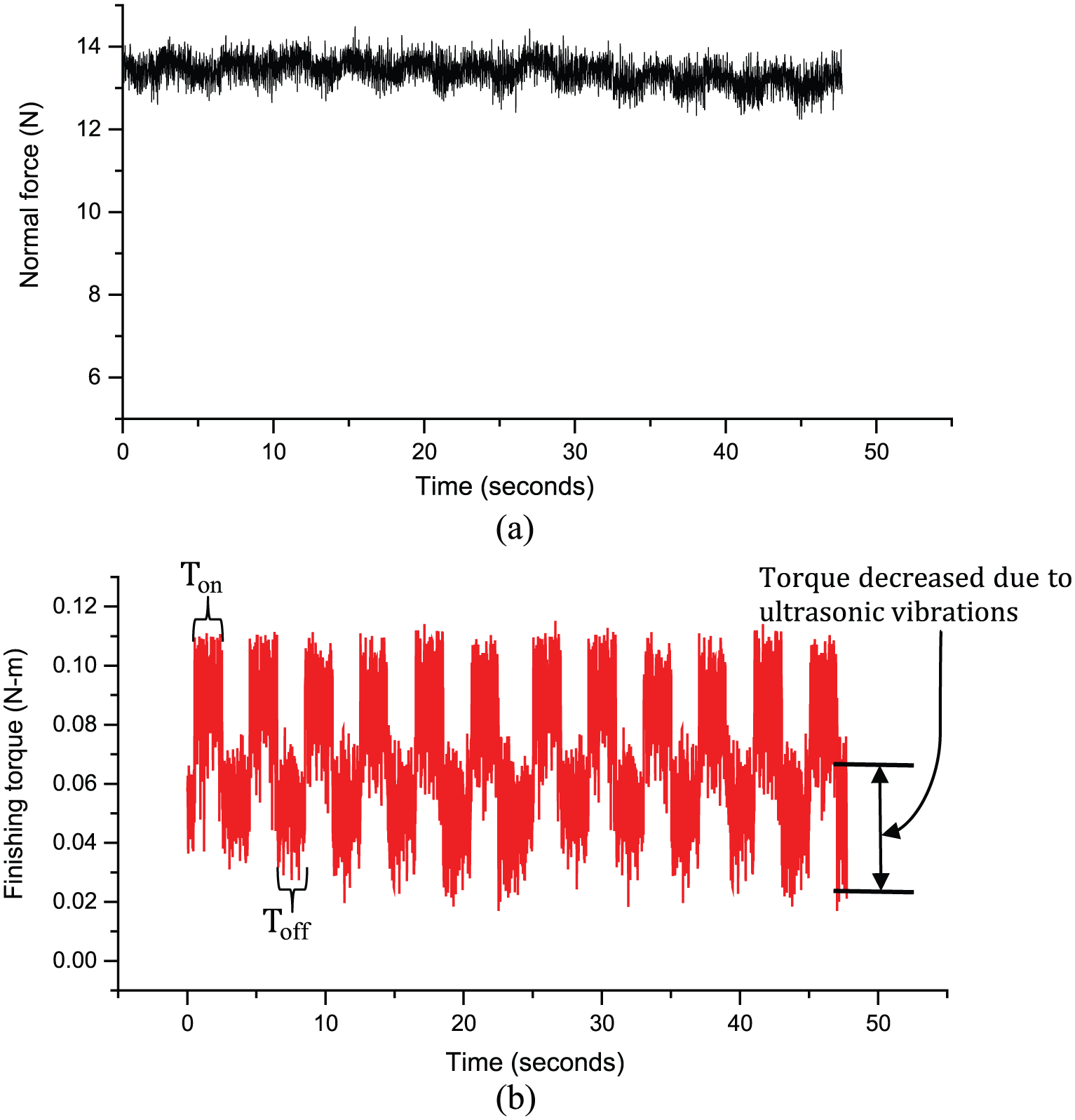
Variation of measured (a) normal force and (b) finishing torque with time, at 60 V, 1.5-mm gap
From Figure 8(a), it can be observed that there is no significant variation in the normal force during
Results and discussion
To check the validity of the developed force model, the simulated values for the normal force and the finishing torque were compared with the experimental results. The material properties and machining parameters used in the simulations were as follows: density of SiC abrasive
Voltage
In the UAMAF process, the input voltage to the electromagnet produced the magnetic field, controlling the magnetic pressure applied by the FMAB on the surface of the workpiece. Figure 9(a) and (b) demonstrates the comparison of calculated and experimental values of the average normal force and the finishing torque for different levels of supply voltage. The effect of voltage on the average normal force is shown in Figure 9(a); it is observed that the force increased with voltage. This is attributed to the fact that with increased voltage, the average magnetic flux density in the finishing gap increases, thus forming strong chains of ferromagnetic particles, causing an increase in the yield strength of the FMAB. Hence, active abrasive grains in FMAB create a higher normal force on the surface of the workpiece. The increased average normal force on active abrasive grains caused greater indentation of abrasive grains into the workpiece surface; hence, the torque required to rotate the brush increased (Figure 9(b)).
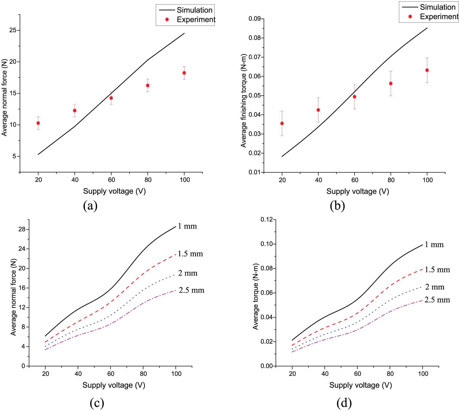
Comparison of experimental and predicted values of (a) average normal force and (b) average finishing torque during UAMAF gap of 1.5 mm; parametric analysis of (c) average normal force (d) average finishing torque for different values of supply voltage at varying working gap.
There is some deviation of theoretical results from experimental observations. At a lower voltage, abrasive and ferromagnetic particles were not rigidly held together. Hence, during finishing some abrasive particles dropped down from the FMAB and formed a micro-layer under it. Effectively, the finishing occurred with a much higher number of active abrasive particles than assumed. The magnetic levitation force acting on them produced relatively higher force. As the voltage increased, the FMAB gained the strength; also, the bonding strength between abrasive and ferromagnetic particles increased. The amount of actual active abrasive particles on the workpiece surface reduced. At a very high voltage, only a fraction of the calculated active abrasive particles acted on the surface. Also, the effect of vibrations reduced the normal force that was not accounted in the model. Hence, the calculated forces and torque were greater than experimentally observed values. Figure 9(c) and (d) shows the trends for average normal force and finishing torque with supply voltage at different working gaps as obtained in the simulations. It is concluded from the figure that the increasing gap at the fixed voltage results in a decrease in the normal force and the finishing torque.
Working gap
The working gap refers to the distance between the electromagnet and the surface of the workpiece in UAMAF. Figure 10 shows an increase in the average normal force and the finishing torque with a decrease in the working gap in UAMAF. It is due to the fact that a smaller working gap results in a higher magnetic flux density; hence, a higher magnetic pressure acted on the workpiece surface resulted in a higher normal force exerted by FMAB on the workpiece surface. The size of indentation of abrasive depends upon the normal force acting on it, and the radius of indentation affects the coefficient of friction (equations (16)–(19)) and, thereby, the finishing torque. Hence, the finishing torque also decreases with an increase in the working gap as observed from Figure 10(b).
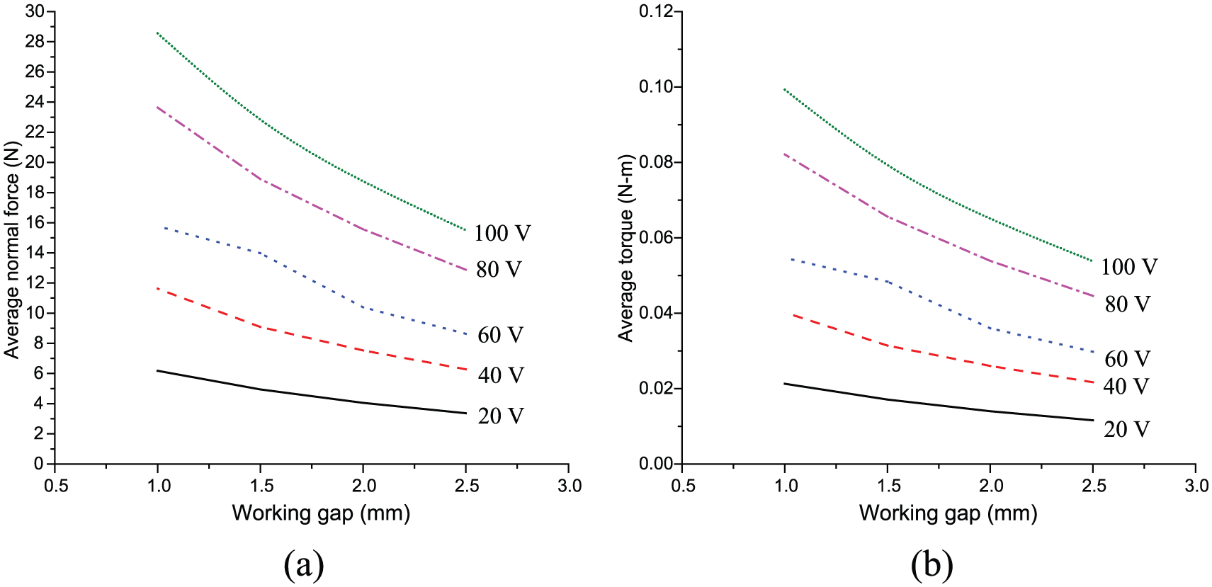
Effect of working gap on (a) averaged normal force and (b) averaged finishing torque during UAMAF for different supply voltages.
Concentration of abrasives
The mass fraction of abrasive in the FMAB is the ratio of the mass of abrasive particles to the total mass of UMAPs (ferromagnetic and abrasive particles). The abrasive particles are generally of non-magnetic nature. Hence, their magnetic permeability is very small compared to that of ferromagnetic particles. The addition of abrasives to ferromagnetic particles will tend to reduce the magnetic permeability of the FMAB. Therefore, its magnetic permeability depends upon the magnetic permeability of ferromagnetic and abrasive particles and also on their individual quantity in UMAPs. The effect of mass fraction of abrasive particles in the FMAB on the average normal force is shown in Figure 11. Both parameters decreased with an increase in the mass fraction of abrasives. This was due to the fact that an increasing amount of abrasive particles in the FMAB reduces its relative magnetic permeability. This reduction diminishes the rigidity of the FMAB and, hence, the force applied by it. Also, it can be concluded from Figure 11 that an increase in the voltage at the same mass fraction of abrasive particles causes an increase in the normal force and finishing torque.
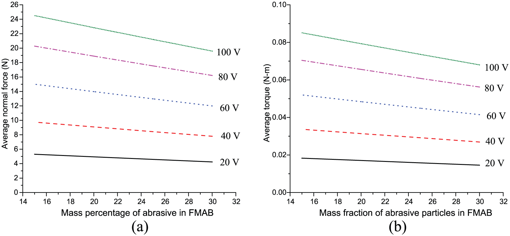
Effect of concentration of abrasives in FMAB on (a) average normal force and (b) average finishing torque during UAMAF for different supply voltages.
Conclusion
In this work, a model of the electromagnet was created and finite element method (FEM) simulation was performed to assess the magnetic flux density on the surface of the workpiece. The theoretical models for the normal force and the finishing torque during UAMAF were also presented. The following outcomes are deduced from the presented analysis:
The simulation of the electromagnet predicted the magnetic flux density on the workpiece surface reasonably well.
It was established by means of mathematical modeling that the finishing torque was directly dependent on the normal force produced by the magnetic field.
The magnetic flux density on the workpiece surface decreased as the working gap increased and increased with supply voltage.
Increased supply voltage resulted in higher normal force and finishing torque.
Increased concentration of abrasive particles in FMAB reduced the normal force and the finishing torque of UAMAF.
The mathematical models for prediction of the normal force and the finishing torque were developed successfully based on the process physics. The developed models were validated with the obtained experimental results and found to be in reasonably good agreement.
Footnotes
Appendix 1
Declaration of conflicting interests
The author(s) declared no potential conflicts of interest with respect to the research, authorship and/or publication of this article.
Funding
The author(s) disclosed receipt of the following financial support for the research, authorship, and/or publication of this article: This work was supported by the Department of Science and Technology (DST; India) and Engineering and Physical Sciences Research Council (EPSRC; United Kingdom) entitled “MAST: Modeling of Advanced Materials for Simulation of Transformative Manufacturing Processes” (grant identifications: DST/RC-UK/14-AM/2012 and EP/K028316/1).