
Abstract
One of the promising and emerging techniques used to improve the tool chip contact phenomenon is to create micro- and/or nanostructures on the surfaces of cutting tools. The rake face structuring of the cutting tool has been the focus of research, and its benefits are well documented in literature. The effects of structures applied on different faces of the cutting tool have been studied in detail, yet there is a scope on cutting performance comparison of structured tools. This study looks into the cutting performance comparison of three fabricated cutting tools: a cutting tool with the rake face structure, a cutting tool with flank face structure and a tool with both the rake and the flank face structure. Structures on the cutting tools were created with a femtosecond laser system. Orthogonal machining of EN19/AISI/SAE4140 was performed to assess the cutting performance of the fabricated structured tools. Machining performance of structured tools was measured against cutting performance of unstructured tool. Results suggest that structured tools deliver better machining performance. However, improvement in certain machining parameter (forces, compression ratio, contact length, etc.) is linked to the structures created on a specific face of the cutting tool, although each structured side of the tool has a counter effect. Structured cutting tools reduce sticking contact from 52% to 42%–45%. Also, structured cutting tools lower the energy consumption due to decreased compression ratio. Precisely this research classifies the preference on the application of tool structuring for improved performance.
Introduction
Surface structuring is a surface modification approach that means to improve the tribological behaviour of the interfacing surfaces. 1 Research on surface structuring has shown that specific structural design gives specific performance. Structuring on the surface can either be performed in a random manner or can be regularly organised. Regularly organised structures are more popular due to its advantage in term of optimum performance. The reasons for improved performance are related to effective lubrication, debris entrapment, reduced contact stresses and/or hydrodynamic lift. 2 In recent past years, the fundamental research on cutting tool structuring has been carried out, and improved tool chip contact phenomenon has been recognised.
Structuring the tool on the rake face has been the area of focus in related research. It has shown potential in lowering cutting forces,3–9 cutting temperature,9–11 tool wear6,9,11–13 and anti-adhesion properties. 14 On an average, reduction in cutting forces up to 30%, compared with the unstructured cutting tool, was reported when machining was performed using the rake face structure cutting tool. The cutting speeds used for the experiments were in a conventional speed regime. From the literature review, it is observed that structures were fabricated on cemented carbide inserts and steel as the workpiece material was machined at cutting speed within the range of 2–300 m/min. Furthermore, when titanium was the workpiece material, the cutting speed in the range of 36–180 m/min can be achieved. On the application of structure on tool rake face, it is established that structures should be fabricated perpendicular to the chip flow direction to make a robust influence for improved cutting performance. Fatima and Mativenga 15 reported that machining performance is greatly influenced by the distance at which the structures are created from the cutting edge. It was concluded in Fatima and Mativenga 15 study that the optimal location to create structures is within 70%–80% of natural contact length, located away from the cutting edge.
From research studies,1,8,10,11 it is revealed that structured tools with the coated rake face were more operational in improving machining performance. It was reported that 10% reduction in cutting forces and 5% reduction in temperature were observed in comparison with the uncoated cutting tool. Only two studies9,11 highlighted the ability of the rake face structured tools to reduce flank wear. However, it was noted that the workpiece used for machining experiments in both studies was titanium alloy.
Compared with rake face structuring, few research studies discussed the performance of flank face structuring of the cutting tools. Tool wear in machining of medium carbon steel was studied by Sugihara and Enomoto. 12 They developed two structured cutting tools: one with structures on rake face while another has structures on flank face. Cutting test showed that the flank face structured cutting tool exhibited excellent flank wear resistance, whereas tool with structured rake face showed effectiveness in reducing crater wear. Ze et al. 9 testified an improvement in life expectancy of the cutting tool by 10%–30% when a self-lubricated flank face structured tool was used in dry cutting of Ti-6Al-4V alloy. Fatima and Mativenga 16 reported a power reduction of 35%, an increased tool life of 18% and an improved surface finish in the machining of AISI 4140 with a flank face structured cutting tool. Only Fatima and Mativenga 2 has explored the performance of cutting tools that have structures on both faces of cutting tool, that is, rake and flank face.
From previous research work, it is revealed that a comparison of machining performance of structured cutting tools has not yet been investigated. In this study, three distinct structured tools were created: (1) a rake face structured tool, (2) a flank face structured tool and (3) both rake and flank face structured tool. The machining performances for these three distinct structured tools were investigated in orthogonal cutting of EN19 alloy steel. Performances were compared with unstructured cutting tool and were assessed in terms of machining performance indicators (forces, compression ratio, tool wear, etc.). The aim of this research work is to identify a preference on the application of structures and, consequently, which face of the cutting tool structures should be applied for enhanced machining performance.
Experimental details
Laser structuring setup
Libra Ti:sapphire femtosecond laser was used to fabricate structures on uncoated cemented carbide inserts (Sandvik TCMW 16T308 5015). This cutting insert was particularly selected because it allows an easy fabrication of structures on the rake and flank face. The laser system utilised for structuring has the wavelength range of 795 nm to 805 nm, a repetition rate of 1 kHz, pulse width of 100 fs and maximum average power equal to 1 watt. With the available laser setup, laser pulse was able to generate a minimum spot size of 30 μm with a scanning speed of 10 mm/s. Justification for the selected laser parameter is based on a previous study conducted by Fatima et al. 17 on the femtosecond laser structuring of carbide. A computer-controlled translation stage was used to mount and hold the cutting tips in front of the focussed laser beam. Structures fabricated on the cutting tool are shown in Figure 1(a). Structure dimensions are listed in Table 1. White light interferometer (WYKO-NT-1100) and scanning electron microscope (SEM) were employed to typify structure geometry (Figure 1(b) and (c)). On average, the structure dimensions were varied to ±5 µm. After laser processing, all inserts were washed for 10 min in deionised water in an ultrasonic tank. This was performed so as to remove debris after laser machining of cutting inserts.
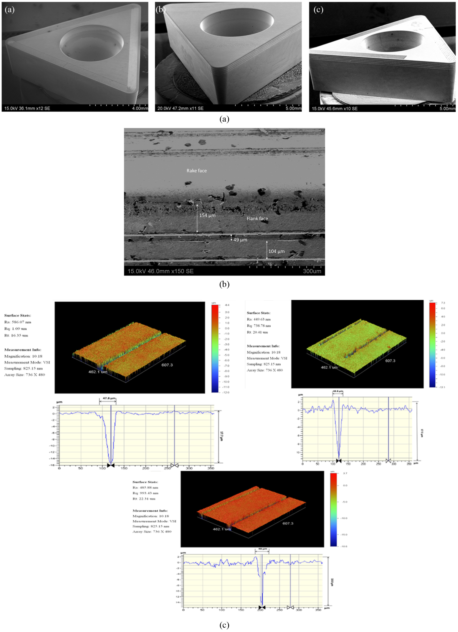
(a) SEM image of fabricated structured cutting insert—a: rake face structured cutting insert, b: flank face structured cutting insert and c: rake and flank face structured cutting insert; (b) geometric detail of fabricated structures; (c) WYKO-NT-1100 image and geometric detail.
Structures dimension specification.
Machining setup
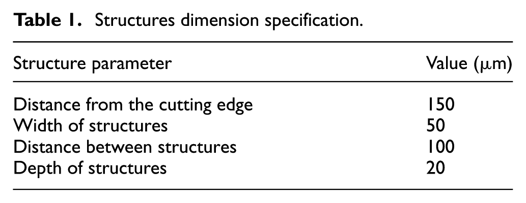
EN 19 alloy steel was selected as a work material due to its wide use in industries. It was machined in a shape of a tube for orthogonal cutting tests. The wall thickness of the tube was 2.5 mm and an outer diameter was of 200 mm. Machining setup is shown in Figure 2(a). The structure’s performance was tested at the cutting velocities of 100, 198 and 394 m/min. These cutting speeds were carefully selected towards manufacturer’s cutting speed specification. For inserts, Sandvik STGCR2020k-16 tool holder was selected as it can hold selected insert geometry design. This tooling system has a 0° rake angle and a 7° clearance angle. Width of cut of 2.5 mm (thickness of a tube) and a feed rate of 0.1 mm/rev was used and kept constant. As a lubricant, cutting compound, Trefolex from warren Bestobell was brushed on structures cutting tools. All the experiments were randomly repeated. To enable structure evaluation and to minimise wear effect, 5-mm linear machining length was used for all the trials of cutting experiment. Fatima and Mativenga 18 have reported the justification for the use of 5-mm length of cut in machining of EN19 to study the tool chip contact phenomenon.
(a) Setup for machining; (b) force and time domain; (c) tool chip contact track; (d) temperature measurement on cutting insert.
Force components were measured by piezoelectric dynamometer type 9263 by Kistler. The average values of the cutting forces were established from the time domain graph, once the forces were stabilised (Figure 2(b)). Contact tracks on the worn-out inserts were assessed to measure the contact length. Since the contact length tracks were not consistent, an average value of contact length was documented by measuring tracks on 10 different location on the contact area (Figure 2(c)). For this purpose, electron scanning microscopy (SEM) was used. The method of chip weight and chip geometry was utilised in calculating the chip thickness ratio (compression ratio). In addition, infrared thermal image FLIR ThermaCAM® SC3000 was used to take measurements on tool temperature (Figure 2(d)). It was positioned at the suitable distance (0.4 m) away from the cutting zone and yet close enough to capture thermal maps on the tool rake face (Figure 2(a)). Recorded thermal maps were evaluated by using software (ThermaCAM Researcher). Average emissivity value (0.48) of cutting tool material, established from furnace measurement, was used for thermal camera setup and calibration in temperature measurement.
Results
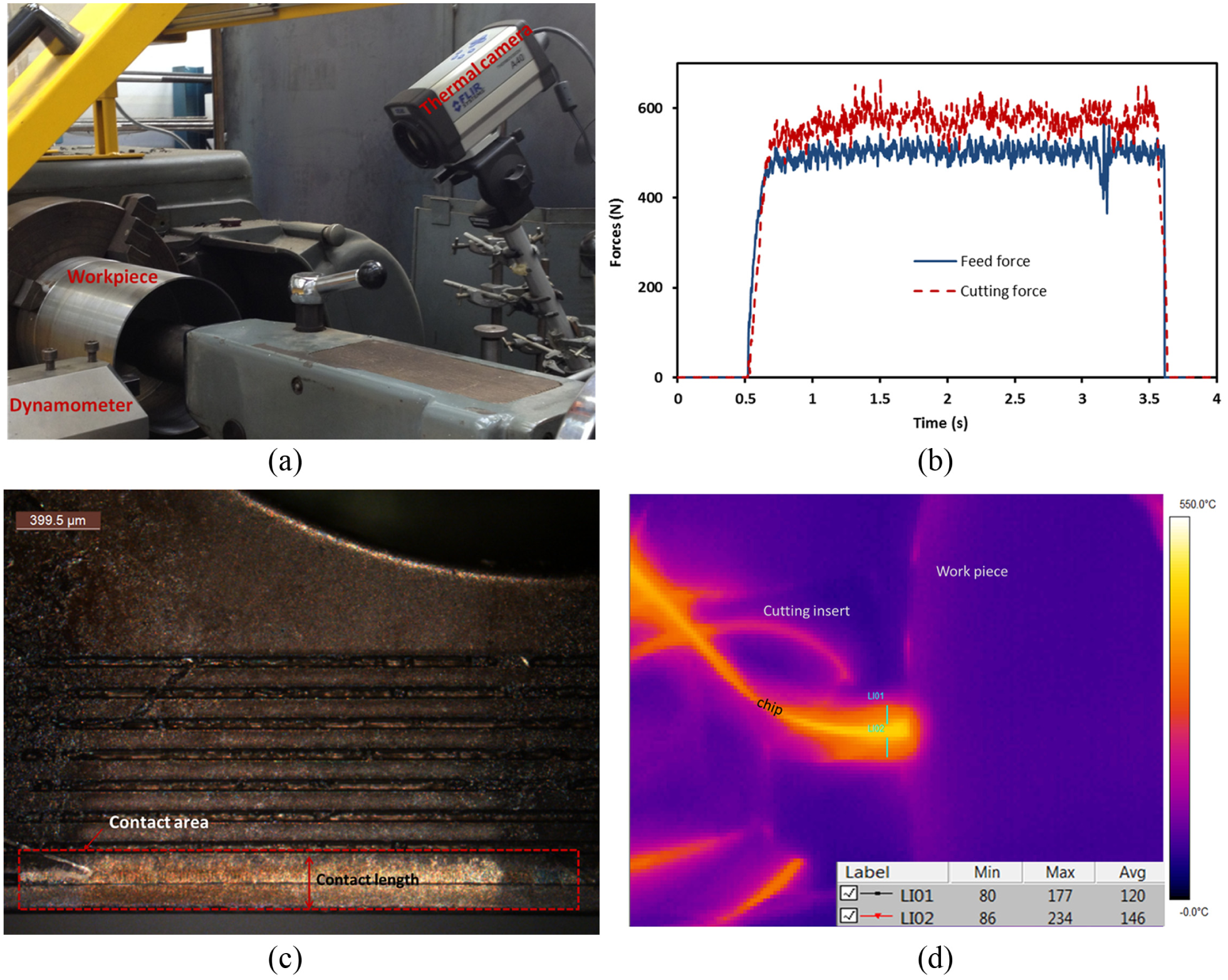
Figure 3 shows the relationship between the cutting forces and cutting velocity for the fabricated cutting tools, at a constant feed (0.1 mm/rev) and width of cut (2.5 mm). Figure 3(a) is the plot for the cutting force while Figure 3(b) is the feed force plot. From Figures 3(a) and (b), it can be observed that the cutting force and the feed tend to reduce in case of flank face structured tool. An average reduction of 17% in cutting force were estimated for flank face structured cutting tool while 12% and 10% were estimated for rake face structured tool and for a tool with both rake and flank face structured, respectively.
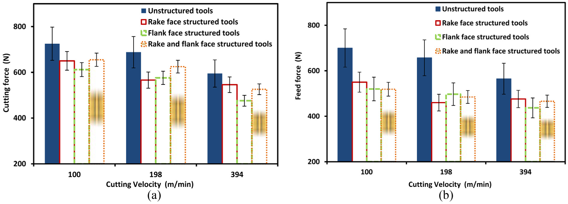
(a) Cutting force versus cutting velocity; (b) feed force versus cutting velocity.
Figure 3(b) shows the feed force trends for all types of cutting tools use in the present study. It can be noticed that the maximum reduction in feed force was observed in case of flank face structured cutting tool. However, there is a consistent reduction in feed forces for the range of cutting speeds for all structured tools. On an average, 22%, 24% and 23% reduction was observed for rake face structured, flank face structured tool and for the tool with both rake and flank face structured, respectively. From all the above cases of structured tool, it is observed that with the increase in cutting speed, the effectiveness of structured tools in reducing forces decreased. Koshy and Tovey 3 have reported similar results in the machining of steel and aluminium with structured cutting tool. The main reason for this phenomenon can be perceived from the insight of metal cutting elementary analysis; it is established that the distance to which the lubricant penetrates the cutting zone is inversely related to the cutting forces. Physically, at higher cutting speed the lubricant ingress into the contact zone is retarded and there is a less time for the lubricant to react with the chip. Also, there is a likelihood that elevated temperature associated with increased speed breaks down the lubricant rendering it to be less effective. Such aspect has reduced the capability of structures to reduce forces at increasing speed as structures were mainly present to act as a lubricant reservoir.
The chip compression ratio is a quick predictor of the deformation level (strain) that a work material experience at the instant of cutting making it a significant machining parameter. Lower values of compression ratio are desirable as it leads to a larger shear angle which results in lower energy consumption and less strain in a chip producing thinner chips. The deviation of compression ratio with respect to cutting velocity for the unstructured and the structured cutting tools is shown in Figure 4. The decrease in compression ratio with the increased cutting velocity is due to thermal softening of the work material. This is well established in the literature. However, in the case of structured cutting tools, a significant improvement in compression ratio was observed. The amount of reduction in compression ratio was prominent in the case of a tool with rake and flank face structured.
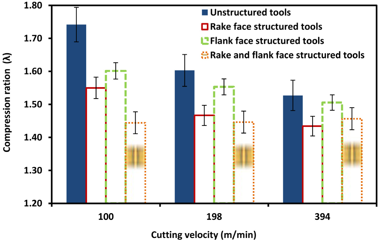
Compression ration versus cutting velocity.
Variation in contact length with cutting velocity for all the cutting tools is shown in Figure 5. As seen from Figure 5, a traditional decreasing trend with increasing speed is observed for a contact length of unstructured insert. Decrease in contact length experienced in the case of the rake face structured tool and flank face structured tool could be due to structures acting as a micro tank for the lubricant. The average reduction associated with the rake face structured tool and the flank face structured tool was of 12% and 16%, respectively. However, in case of a tool with both rake and flank structured, measured values of contact length compared with an unstructured cutting tool were only marginally higher. The sliding contact of the total contact of tool chip interface, in case of rake–flank face structured tool, was found to be increased (Figure 9). This might be a possible effect of low compression ratios related to structuring both faces of the cutting tool (rake and flank face), the use of lubricant and the shape of the structures. In case of rake–flank structured cutting tool, the chips were thinner which make them float easily and because of prolonged lubricant retention in structures due to glass shape cross section of structures the lubricant facilitates the slip of chip.
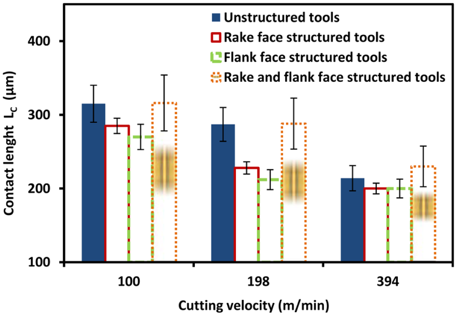
Contact length versus cutting velocity.
Figure 6 shows an average rake face temperature on the structured and unstructured cutting tools for the selected cutting velocities. As indicated from Figure 6, a rise in cutting temperature is noted as the cutting speed is increased. It is a well-established fact that as a cutting speed increases the shear plane gets narrower. The material is forced to deform in narrow plane which increase the temperature. However, the rake face structured tool exhibits a maximum average reduction in cutting tool temperature. Furthermore, it is evident from Figure 6 that the ability of structures to reduce tool temperature decreases as the cutting velocity increases, and in case of the cutting tool with both rake and flank face structured tool, temperature was observed to be marginally greater than an unstructured cutting tool at the highest cutting speed. Similar results were also reported by Ze et al. 9
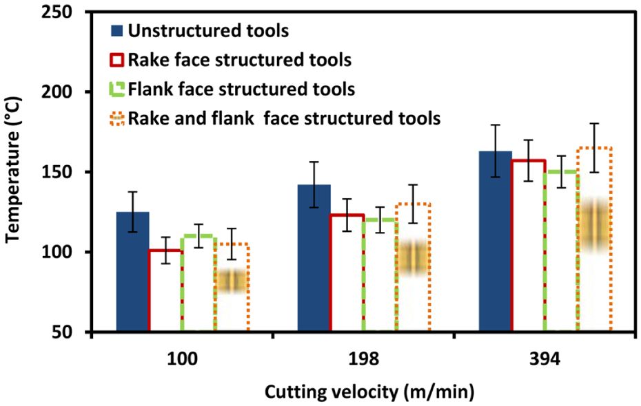
Tool temperature versus cutting velocity.
The machining process is substantially influenced by tool chip contact area. The knowledge of tribological conditions at the tool chip interface can be useful to infer machining process parameters that are efficient and can possibly result in reduced tool wear. Condition at interfaces is determined by a key parameter: the friction coefficient. In this study, equation (1) was used to determine friction coefficient 19
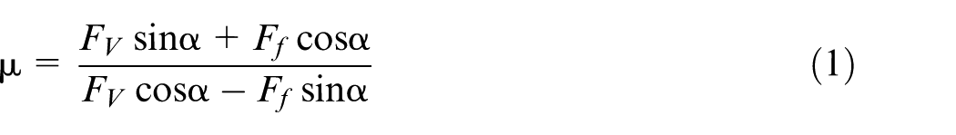
where μ = friction coefficient, α = rake angle, Fv = cutting force and Ff = feed force.
Deviations in the friction coefficient with cutting velocity are shown in Figure 7. Normally, coefficient of friction decreases with an increase in cutting speed, which is due to thermal softening of chip material. The unstructured cutting tool shows a marginal decrease in coefficient of friction. For each selected cutting velocity, when compared with unstructured cutting tools, a decrease in coefficient of friction is evident for all structured cutting tools. It was noted that on average, the reduction in friction coefficient for the rake face structured tool, flank face structured tool and rake–flank face structured tool was of 12%, 8% and 14%, respectively.
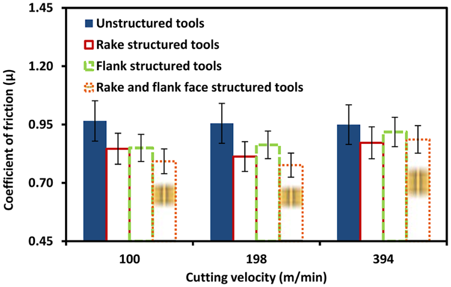
Friction coefficients versus cutting velocity.
Reducing tool wear is important as it affects the economics of the machining process. Scanning electron microscopy (SEM) was utilised in this study to measure flank land wear on worn-out inserts. Figure 8(a) shows dissemination of flank wear for all fabricated structured cutting tools for selected cutting velocities, whereas Figure 8(b) shows the SEM image of flank land wear measurement. As established, for unstructured cutting tools, flank land wear develops a traditional increase with increased cutting speed. Among structured cutting tool, the rake face structured cutting tools show higher tool wear than unstructured tools, whereas cutting tools with both the rake and flank side structured developed a lower wear at low cutting speeds, but increased wear at higher cutting speeds. As for the flank face structured tool, wear was lower in value than an unstructured cutting tool.
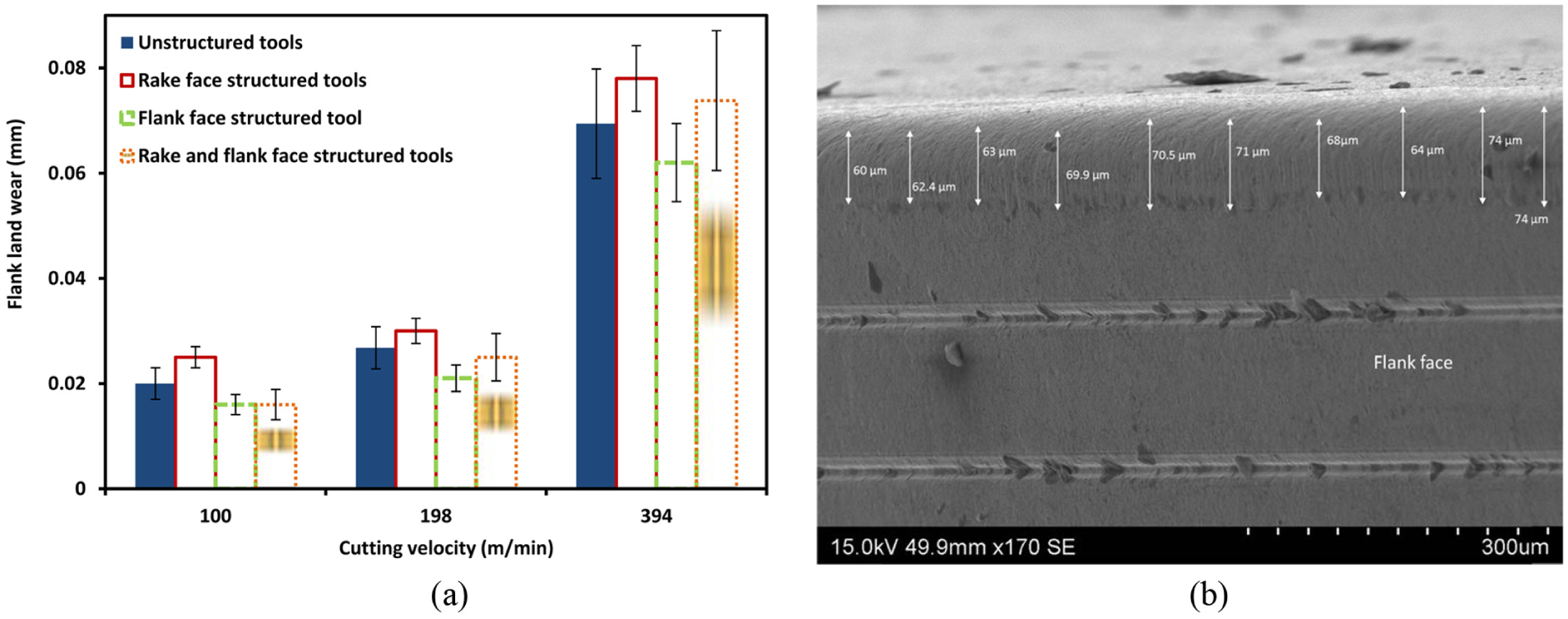
(a) Flank land wear versus cutting speed; (b) SEM image of flank land wear measurement of flank face structured cutting tool for the cutting velocity of 394 m/min.
Contact phenomenon
Information on iron distribution to identify sticking and sliding contact was obtained using a scanning electron microscopy, energy dispersive x-ray (SEM-EDX) line scan. It is an established technique to quantify iron weight transfer to the cutting tool from the workpiece. The high concentration of iron indicates the presence of sticking contact.20–23 Figure 9 presents the results obtained from EDX analysis. Measured contact length for each cutting tool is shown in graphs in Figure 9. From Figure 9, for a speed of 198 m/min, results confirmed that no high concentration of iron appears on the tool’s rake face. This indicates the solitary presence of sliding region. The average iron wt% transfer on the rake face of unstructured tool was 25%. It dropped to 16% for the rake face structured tool, 20% for the flank face structured tool and 21% for the cutting tool with both rake and flank face structured. When cutting tools were tested for the cutting velocity of 394 m/min, near the cutting edge, high peaks of iron were identified on the tool chip contact. This postulates the existence of sticking contact closer to the cutting edge. Fifty-two per cent of the total contact on rake face of unstructured tool was sticking. In case of structured cutting tools, this reduced to 42%–45%. The average wt% transfer of iron was 36% in case of unstructured tool. For structured cutting tool, it reduces to 20% for rake face structured tool, 27% for flank face structured tool and 29% for both rake and flank face structured cutting tool.
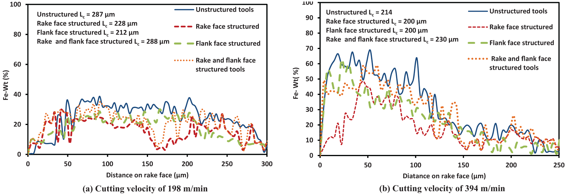
SEM EDX analysis of cutting tools at cutting velocity of (a) 198 m/min and (b) 394 m/min.
Discussion
From the results, it is observed that regardless of which face structures were created, structured tools show effectiveness in reducing temperature. Heat is partitioned into the cutting tool through the corresponding contact of chip and workpiece on rake face and the flank face of cutting tool. Structures on the cutting tools have reduced tool chip and tool workpiece contact area and have thus decreased tool temperature. Furthermore, structures on the tool also act as the site to retain cutting fluid. From this structural site, lubricant is squeezed out and forms a chemically reactive surface layer of adsorbate. The film of the adsorbate on the contact zone reduces the direct contact at interfaces and thus reducing tool temperature. 2 However, such (chemical) film has limited effectiveness. Temperatures above their melting point could cease their interpreted function. 2 Moreover, structures delivered more apparent performance in reducing tool temperature, when tested at lower cutting velocity as compared with higher velocity. This can be attributed due to the fact that the transition range to high speed machining of EN19/AISI/SAE4140 is 394 m/min, and it has been established that high speed machining is associated with high temperature as a consequence of the narrow shear plane (high shear angles).Therefore, it is likely that the ability of structured to reduce temperature at a higher cutting velocity is compromised due to the high temperature linked to higher cutting velocity. Moreover, high temperature increased the chances of diffusion of chip material into the cutting tool as the yield strength of the chip material is decreased. 24 Furthermore, the edges of the structures can erode the chip material and might facilitate this phenomenon, increasing the tool temperature. In case of rake–flank face structured tool, the probability of diffusion was high as the edges of structures on both the tool faces accelerate this phenomenon.
Friction coefficient was reduced as a result of tool structuring. The friction coefficient is a function of the friction and the normal force acting on the contact area. 2 Moreover, chip load is a measure of thickness of chip during a cut and is also a measure of heat taken away from the cut. Thinner chips are accompanied with low compression ratio values. This indicates that the less friction force is required to shear the chip material across the tool chip interface. 2 Also, for the cutting tool of zero rake angles, feed forces are considered to be equivalent of friction forces. Because of this correlation, a decrease in feed force is observed for structured tools. While, shearing process and friction affects the cutting forces. 3 In this case, it can be inferred that low values of friction coefficient and compression ratio related to structured tools contributed towards lower cutting forces. Cutting forces are also directly related to tool wear. Tool wear, typically flank wear progression which is considered as a major tool, fails criteria as it develops quicker than crater wear. Besides, Sugihara and Enomoto 12 reported that structures created on the rake face reduce crater wear and structures created on the flank face reduce flank wear on a cutting tool. In aspect of this research, it can be concluded that since flank face structuring greatly reduces flank wear, the forces in case of flank face structuring were significantly reduced. However, in case of the rake face structuring, the flank wear was high. This possibly could be a consequence of lubricant as hydrodynamic lift evolved from lubricant action might have pushed the chip towards flank side barging in the natural chip flow. In case of rake–flank face structured tool both of the above mention stroke were simultaneously taking place; therefore, it can be clinched for the decrease in cutting forces less than in case of rake and flank face structured tools.
Tribological condition (friction) at tool chip interface is subjective to the prevailing contact conditions. In a comprehensive study on the nature of chip curl and chip breaking effect by Fang and Jawahir, 25 it was proved that tool life and cutting forces are affected by both parameters of chip flow. Jawahir et al., 26 in study of restricted tools for optimum machining performance, identified tool-face land, geometry of back wall and depth of chip groove as influential parameters of the chip groove design for effective chip curl and breaking. In light of Jawahir et al.’s 26 study, it is supposed that tool face land should blend smoothly with the groove depth which is further blended smoothly with the back wall of the groove, providing resemblance to a spherical crater 2 (Figure 10(a)). In a study by Fatima et al. 17 on the femtosecond laser structuring of carbide inserts, the authors have identified a structure’s cross section resembling glass shape with sharp edges (Figure 10(b)). It was argued that this cross-sectional shape of structures is a consequence of the Gaussian distribution of the laser beam. 2 Hence, the situation predicates that the glass-shaped cross-sectional grooves (Figure 10(b)) preserved lubricant effectively and over a long period of time facilitating the hydrodynamic action of the lubricant. This might have resulted in an increased chance for the chip to move steadily over the contact area and has possibly an effect on the chip curl/breaking. From this, it can be observed that there is still an area of improvement in the structure’s shape optimisation. Detailed analysis of effects of structures shape to promote reduced cutting temperature, tool wear and cutting forces, particularly at higher cutting speed, is an open research challenge.
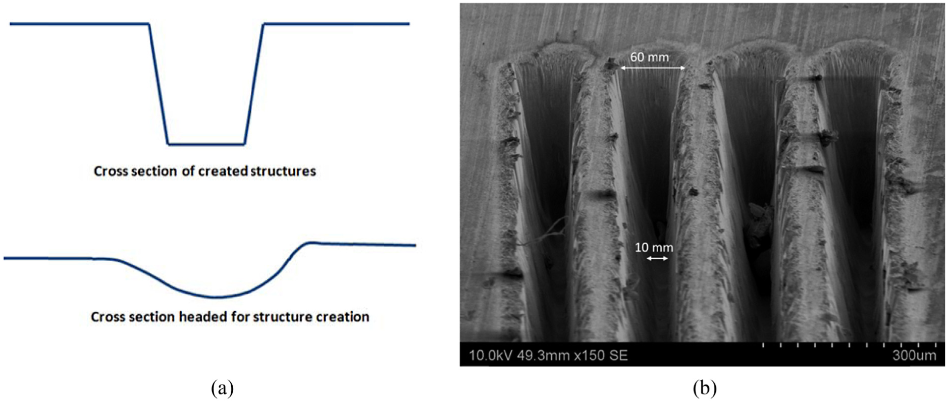
(a) Actual and ideal structure cross section 2 ; (b) SEM image of laser kerf.
Results and discussion presented in the previous sections have identified the new direction in the application of structures and their significance on a particular face of a cutting tool. From preliminary tests, it existed that structuring both rake face and the flank face might bring optimum machining performance. However, results suggest that there is a counter effect of each particular structured side of the cutting tool. In this research study, it was observed that a structures shape plays a critical role in directing chip flow and, hence, this needs to be optimised to improve machining and wear performance.
Conclusion
In this work, different faces of the cutting tools were structured and their performance was experimentally studied in cutting of EN19. Criteria for comparing performances were cutting forces, tool temperature, tool wear, coefficient of friction and iron concentration transfer on rake face. The following conclusions are drawn:
Flank face structured tools can effectively reduce flank tool wear and show better ability to reduce tool temperature at higher cutting speeds. On average, cutting forces were lower in case of flank face structured cutting tool. Tool with both flank and rake face structured delivered low friction coefficient. Results indicated that maximum reduction associated with particular machining performance parameters with structures tools corresponds to the structures created on a particular face of the cutting tool.
Sticking contact phenomenon is a dominant factor of heat dissipation into the tool which promotes tool wear. In this study, structured tools have shown potential to effectively reduce the sticking phenomenon. Surface structuring of a cutting tool has significantly reduced the sticking contact percentage from 52% to 42%–45%. For the cutting tool with a structured rake face, sticking contact was shifted further away from the cutting edge. This condition helps in a favourable flow about the cutting edge and improves performance and suppresses crater wear. Wt% transfer of iron was also reduced due to tool structuring; 16%–29% reduction was observed in case of structured cutting tools.
A prominent reduction in compression ratio was observed when structured cutting tools were used. This indicates the ability of structures to produce thinner chip which yields lower energy consumption.
In comparison with the unstructured tool, the tool with the flank face structured showed the ability to abridge flank wear development at higher cutting velocity. Rake face structured tool fails to show reduction in flank wear, whereas the tool with rake and flank face structuring has only shown its ability to reduce flank wear when cutting velocity was in conventional regime.
To improve the machining performance, optimisation of structure cross-sectional shape is an area of open research. However, with the existing study it is evident that structuring of cutting tools can elevate the machining performance. The overall economics of the machining process is greatly influenced by tool life and thus the tool wear. In light of this, flank face of a cutting tool can be considered prime to structuring as it has shown a maximum potential for wear resistance. However, hypothetically, it is recognised that structuring a particular face of cutting tool has advantages but with counter effects.
Footnotes
Declaration of conflicting interests
The author(s) declared no potential conflicts of interest with respect to the research, authorship, and/or publication of this article.
Funding
The author(s) received no financial support for the research, authorship, and/or publication of this article.