
Abstract
Changing environmental awareness has led manufacturing industry to give critical consideration to the use of conventional coolants and traditional cooling techniques in machining processes. This research shows that impinging gas jets have a much greater potential for reducing the temperature in cutting operations than previously suspected. In this work, the mechanical effect produced by a high-speed air jet impinging on the cutting area at different directions and pressures was critically investigated. Experimental tests with different pressures and nozzle directions indicate that the mechanical effect of the air jet contributes significantly to the reduction in cutting temperature. The tests were carried out on AISI 1020 workpiece and the temperature was measured by a K-type thermocouple embedded in the WC insert. Better performance in terms of cooling is shown when the air jet is directed onto the top face of the chip. The air jet impinging on the surface of the workpiece in the contact zone, on the tool and on the chip introduces both thermal and mechanical effects. Heretofore, these influences have not been examined together. Finite element analysis shows that the mechanical effect of the air jet, impinging on the chip, causes an alteration of the state of stress on the rake face. A theoretical explanation based on this observation is proposed, and the results of experimental, finite elements and analytical modeling are compared.
Introduction
The challenges associated with environmental protection and energy efficiency in relation to manufacturing are now an area of ongoing and vibrant research activity, as outlined by Byrne et al., 1 Klocke and Eisenblätter 2 and Weinert et al. 3 According to Klocke and Essel, 4 the increase in power to remove more material in a shorter time increases the heat generation near the cutting edge of the tool. The temperature achieved by the cutting tool is one of the main factors that limit the rate of machining. 5 The approaches used to manage temperature at the tool–chip interface can be broadly classified as management of the temperature by heat transfer (use of cutting fluids, minimum quantity lubrication and alternative cooling methods) or management of temperature by manipulation of frictional contact. 6 The manipulation of the frictional contact can be achieved using an external source of energy for promoting a deformation in the chip. The mechanical effect of the high-velocity air jet is considered as a pressure applied to the top face of the chip or into the interface between the bottom face of the chip and the tool, altering the state of stress in the insert and on the rake face with a consequent alteration of the frictional contact in the chip–tool interface. This hypothesis is consistent with the observation of Baker. 7 The aim of this research is to investigate the use of a high-velocity air jet to assist the orthogonal cutting process, both from a thermal and a mechanical point of view. A particular focus of this work was the mechanical effect of the air jet impinging on the cutting zone. The approach proposed in this article is based on experimental investigations, finite element analysis and analytical modeling of the orthogonal cutting process assisted by high-speed air jet. A previous research carried out by Bareggi et al. 8 shows a similar approach to the problem of three-dimensional (3D) turning assisted by air jet of AISI 1020 steel and two-dimensional (2D) simulation of titanium alloy machining. 9 This research revealed that orthogonal cutting experimental setup and modeling offer a deeper insight into the problem, including an improved analytical model, a measurement of the precise position of the nozzle and a sensitivity analysis of the effect of small variation in nozzle positioning and variations in the air jet pressure.
Materials and methods
The influence of air jet in orthogonal machining was experimentally investigated, with particular emphasis on the thermal effects in the chip–tool interface. An AISI 1020 workpiece was machined with the commercial cutting tool by Sandvik, the TNMG 11 03 02-MF 4025 for high-performance cutting. The insert in WC had a multilayer coating constituted by 4°µm of TiC and 4°µm of TiN. The geometry of the insert presented a chipbreaker with a positive rake angle of 5°, so that the overall rake angle due to the toolholder (negative rake angle of 5°) was 0°. In order to approximate the orthogonal cutting with a turning machine, a thin-walled tube was used. The mean diameter of the tube was 71 mm and the thickness was 1 mm. Experiments were carried out on an URSUS 225 center lathe, cutting forces were detected by a three components Kistler dynamometer, chip–tool interface temperature was detected by a K-type thermocouple embedded in the insert, and a supersonic air jet nozzle was positioned in the proximity of the cutting area. Figure 1(a) shows a sketch of the cutting area with the nozzle in two different positions, called “overhead” and “interface,” with reference to the zone of impingement. The cutting tests were carried out at the cutting speed Vc = 83 and 129 m/min and feed rates t = 0.06 and 0.12 mm/rev. The use of a supersonic air jet as a cooling method introduces new variables in the tests, such as the air jet pressure, the relative distance from the exit section of the nozzle to the edge of the insert and the relative angle from the nozzle axis to the plane of the rake face. The tests carried out for this work aim to investigate the effect of the air jet in the orthogonal machining process, and therefore, a sensitivity analysis on air pressure and nozzle positioning was carried out. The choice of embedding a K-type thermocouple in the insert as a temperature measurement technique introduces an uncertainty that was investigated using multiple holes for embedding the sensor, and the comprehension of thermal behavior of the system constituted by the insert and the thermocouple was the objective of a 3D finite element analysis.
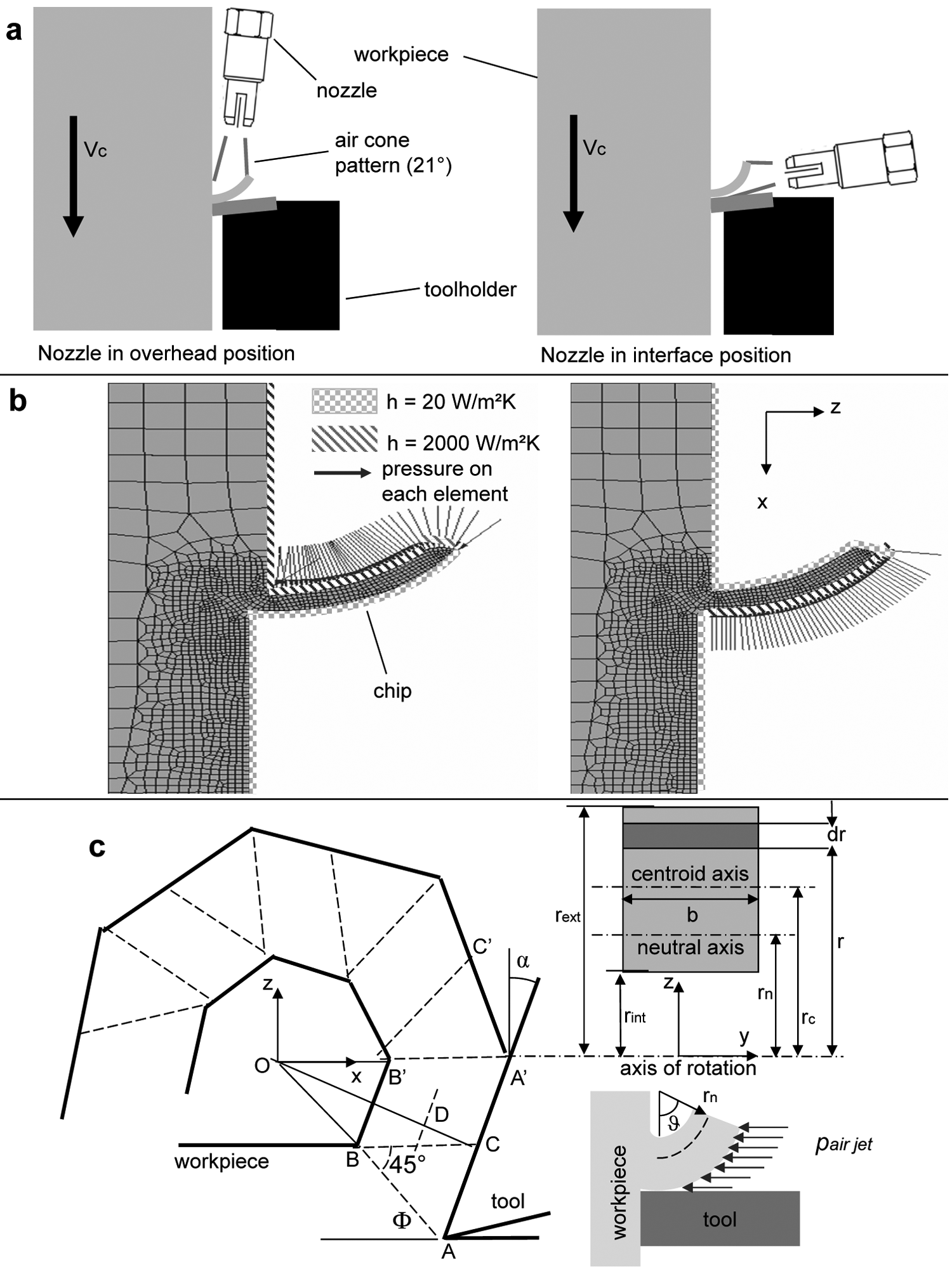
(a) Sketch of the orthogonal cutting process with air jet nozzle in overhead and interface position, (b) thermal boundary conditions for the workpiece in the finite element model and (c) sketch of the simplified chip model (plane x–z on the left-hand side, plane y–z on the right-hand side) used in the analytical model.
Experimental investigation
A supersonic nozzle with a round exit section (diameter of 1 mm) was used for directing the air jet in four different positions (two in the chip–tool interface and two overhead on the top face of the chip). A mass flow meter FMA-1600A and a pressure regulator were placed in the air supply line before the nozzle. Two pressures were used during the tests: 4 bar with a mass flow rate of 0.0132 kg/s and 7 bar with a mass flow rate of 0.11207 kg/s. The thrust of the nozzle was measured by installing the nozzle on a dynamometer: a thrust of 22.2 N was obtained with an inlet pressure of 4 bar and a thrust of 46.6 N was obtained with an inlet pressure of 7 bar. During the cutting tests, the nozzle was positioned at a distance of 12 mm (according to O’Donovan, 10 more than six times the throat section diameter for a fully developed jet and constant blowing force) from the rake face also for allowing optimal chip. The exact position of the nozzle was measured using a distant camera. The measurements taken in the cutting tests consist in force and cutting temperature measurement. The forces were measured by a three-component dynamometer, and the cutting temperature was measured using a thermocouple embedded in the insert. A spark eroder was used for drilling holes in the insert for the thermocouple.
In order to get reliable results, the thermocouple was placed in two different holes; therefore, there are two tests for each cutting configuration (cutting speed, feed rate and position of the nozzle). The system constituted by the insert and the thermocouple was calibrated using an external source of heat that provided a constant temperature on the rake face. The method of embedded thermocouple was extensively used and studied by Attia and Kops11–14 and Grzesik. 15 The limitations of a direct measurement can be avoided if a relation between the maximum insert temperature and the temperature read by the thermocouple is found. The use of the calibration technique associated with 3D finite element analysis (insert and thermocouple under thermal load) allows obtaining a linear relation between the maximum temperature at the chip–tool interface and the temperature read by the thermocouple, as proposed by Ren et al. 16
The tests listed in Table 1 are designed to provide adequate insight into orthogonal cutting assisted by a high-speed air jet, with different cutting speeds, different feed rates, different nozzle positions (including sensitivity analysis of the positions A and B) and different pressures (including sensitivity analysis). The sensor reliability was investigated by eight tests with no air jet in use (dry cutting only), the thermocouple in the two holes of 0.58 mm drilled at 0.25 mm of distance from the rake face and the four possible combinations of cutting parameters (Vc and t). The sensitivity to air jet positioning was investigated by 64 tests with the air jet in the four different positions (overhead A and B and interface A and B) with two different pressures (4 and 7 bar), the thermocouple in two positions and the four possible combinations of the cutting parameters.
Scheme of the experimental tests, including sensitivity analysis.
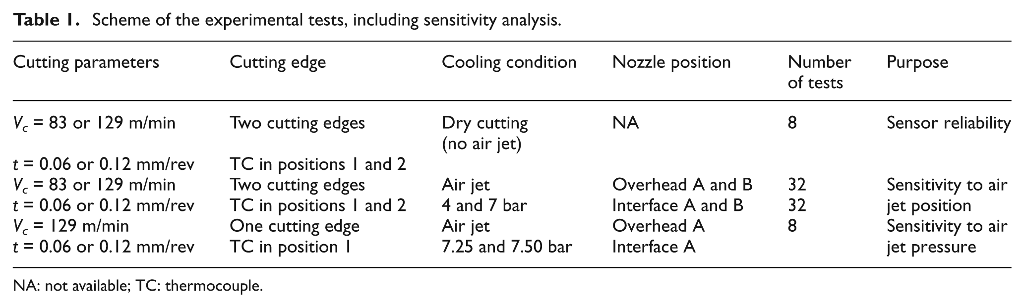
NA: not available; TC: thermocouple.
Finite element analysis
The 2D simulations of orthogonal cutting were modeled using DEFORM-2D. The boundary conditions, shown on the workpiece in Figure 1(b), included the heat transfer by impinging jet, modeled as forced convection using a heat transfer coefficient (h = 2000 W/m2 K), and the mechanical effect of the air jet on the chip, modeled as a pressure applied on the impinged surface. The sensitivity to local heat transfer coefficient in machining operation is low enough to consider only the order of magnitude of local heat transfer coefficient in machining operation, 17 as pointed out by Umbrello et al. 18
The 2D simulation results include the temperature distribution within the insert and the workpiece, the effective stress distribution within the insert and the workpiece and the 2D chip morphology. The temperature and stress distribution within the insert were particularly influenced by the variations in the direction and pressure of the air jet, as also observed by Diniz and Micaroni 19 in low-carbon steel turning tests. The blowing force is represented by a pressure on the elements exposed to the air jet, and the thermal effect was modeled by setting the heat transfer coefficient to 2000 W/m2 K, as in the literature,20,21 with a fluid temperature of 7 °C (measured by a thermocouple placed at the exit of the nozzle). The main limitation of the model represented in Figure 1 is the assumption that the blowing force of the air jet generates an evenly distributed pressure on the chip, in both overhead and interface positions. However, the simplification made represents a reasonable approach without solving the fluid mechanics problem of chip–fluid interaction. The results from the incremental 2D simulations include the cutting forces, temperature distribution within the workpiece and stress distribution within the workpiece.
Theoretical analysis
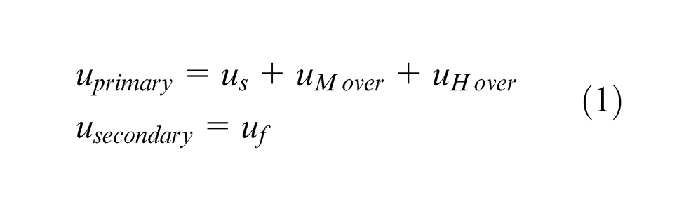
The purpose of the analytical model developed for this work is to provide a deeper insight into the mechanical and thermal effects of air jet-assisted orthogonal cutting. The model is based on energy balance in the orthogonal cutting process with the contribution of the air jet, which was considered as an external source of energy (thermal and mechanical). The components of the specific energy (us
in the shear zone and uf
in the friction zone) were the inputs of the model developed by Shaw,
22
which calculates the temperature in the shear zone, and Jaeger,
23
which calculates the temperature rise in the friction zone according to the flash temperature theory
24
and the maximum insert temperature. The flow stress model of Johnson–Cook was chosen in order to provide stability in the cutting force and in the cutting temperature on a wide range of cutting parameters (42 m/min < Vc
< 290 m/min and 0.03 mm/rev < t < 0.24 mm/rev). The curve of flow stress for AISI 1020 as a function of temperature is not steep for the values of the effective strain and effective strain rate considered in the experimental cutting conditions, obtained by finite element modeling: 3.5 < ε < 3.7 and
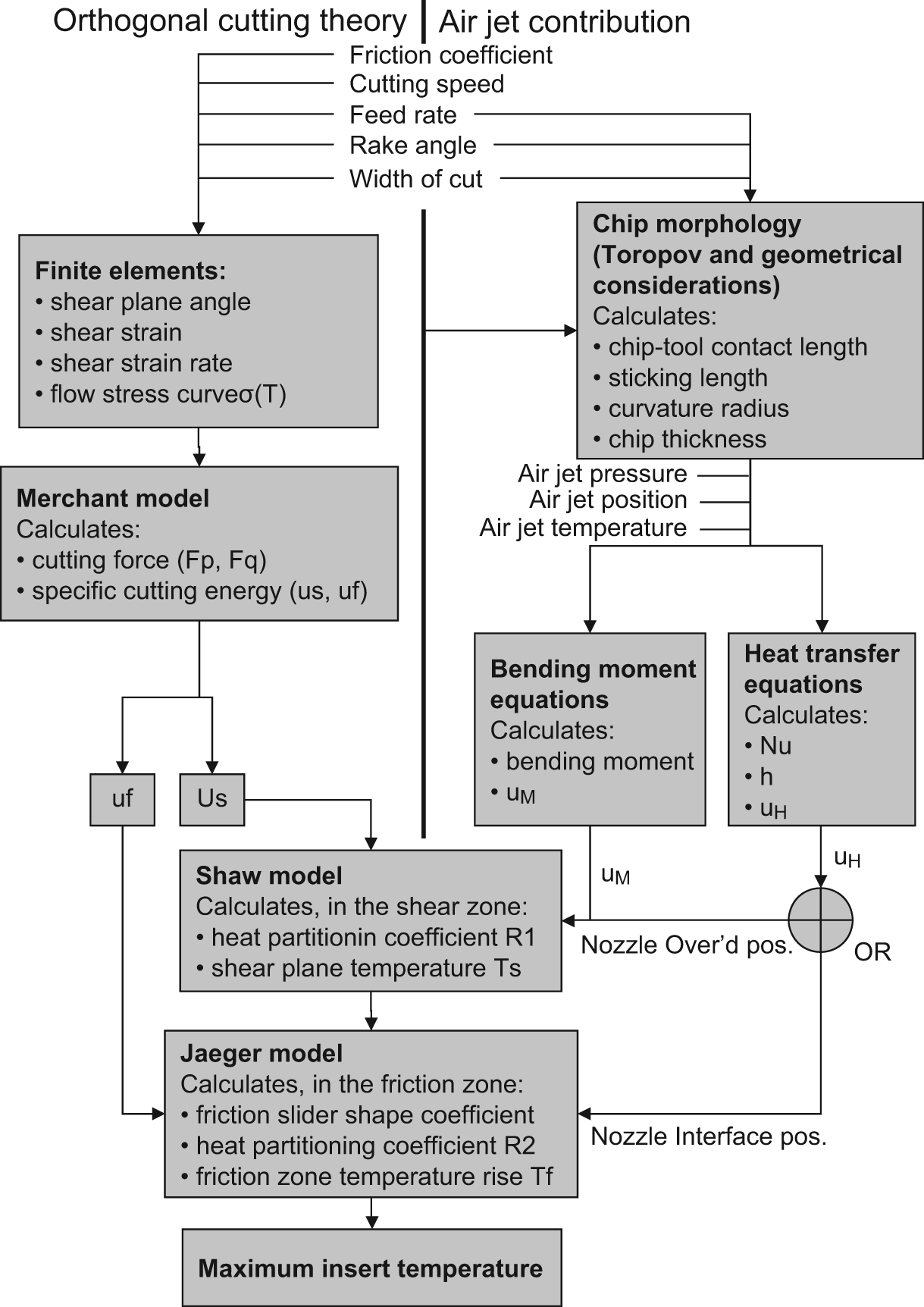
Plan of the analytical model. Based on the balance of energy per unit volume, the model merges the orthogonal cutting model, the elastic deformation of the chip due to the air jet and the heat transfer of impinging jet on curved surface.
The energy balance in the case of air jet directed into the interface is

Modeling of mechanical effect of the air jet
Most of the analytical models for predicting cutting performance are based on the hypothesis that all the shear stress is concentrated on the shear plane, but in fact the shear zone, which can be approximated as a perfectly plastic zone, has a thickness. The strategies for improving cutting through an external source of energy, including the use of laser and plasma techniques,26–29 include the induction of a state of stress, which changes the size of the plastic zone.
According to slip line theory field,
30
the material moves incompressibly, following the stress trajectory described by the slip line field. According to Zorev,
31
the shear stress in the sticking length
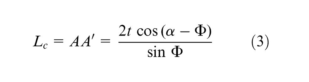
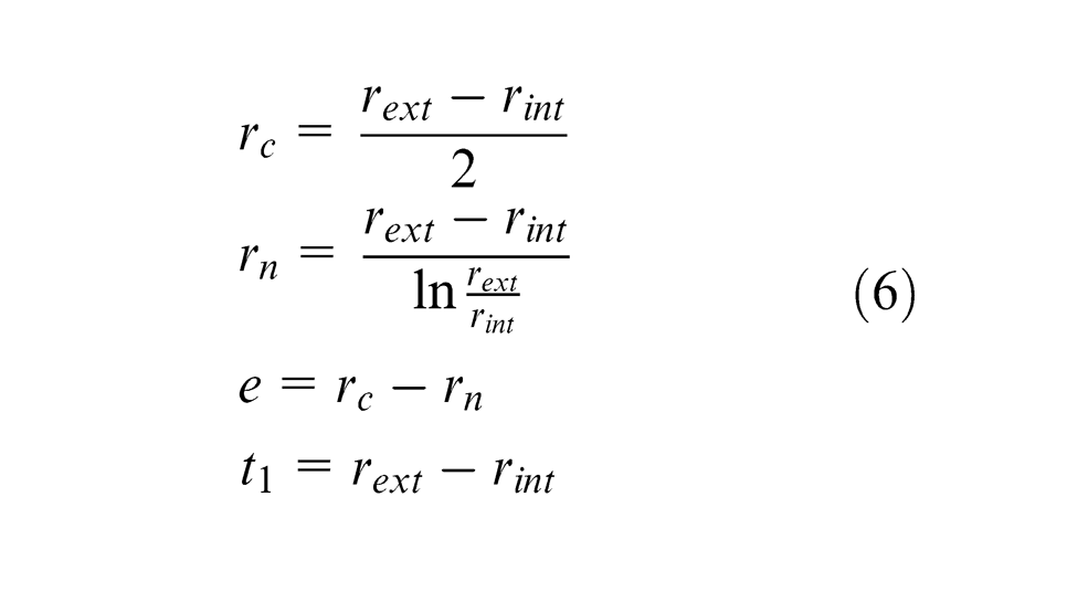
The contact length of the chip with the rake face is used for estimating the chip shape by kinematic relations within the assumptions of the slip line field theory proposed by Toropov. In Figure 1(c), the triangle ABC represents the plastic zone of the chip and the line AA′ is the contact length, which is approximately twice the sticking length. The triangle ABC translates to the position A′, and since the chip is not constrained anymore to the rake face in A′, it rotates according to the plasticization of the workpiece. By geometrical considerations
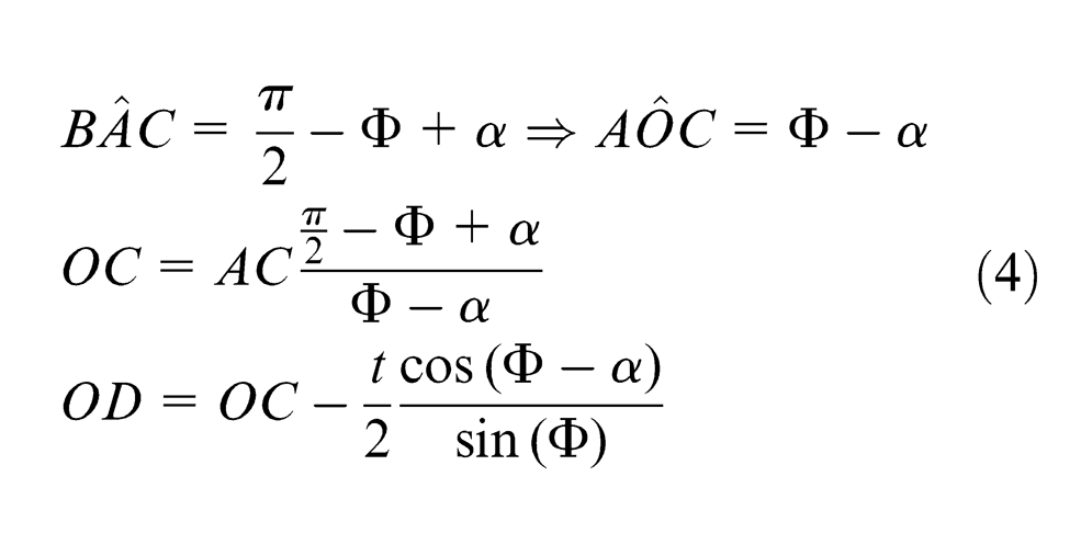
By combining equations (4) and introducing the sticking length AB (Lc ) and by adding to OB half the chip thickness, it is possible to obtain the curl radius rc in orthogonal cutting for a continuous chip and perfectly plastic material
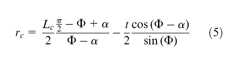
Table 2 shows the calculated chip thickness t
1, the curvature radius rc
of the chip and the contact length Lc
compared to the results by finite elements and experimental tests, based on a wide population of chips collected during the tests. The perfectly plastic material in the slip line field zone is an idealization; however, the kinematic analysis suggests that a link between the chip curl and the shear energy exists. The assumption of a triangular fully plastic zone is a strong simplification. Finite element simulations show that the stress is concentrated along the primary and secondary zones. Minimizing the plastic zone also minimizes the shear energy, and the chip shape (curl radius in particular) is directly related to the minimization of the shear energy, as stated by Baker.
7
From a qualitative point of view, a small curl radius (i.e. a small value of the ratio
Comparative results of the experimental tests, the finite element model and the analytical model for the chip morphology, in terms of chip thickness t 1, curvature radius rc and contact length Lc .
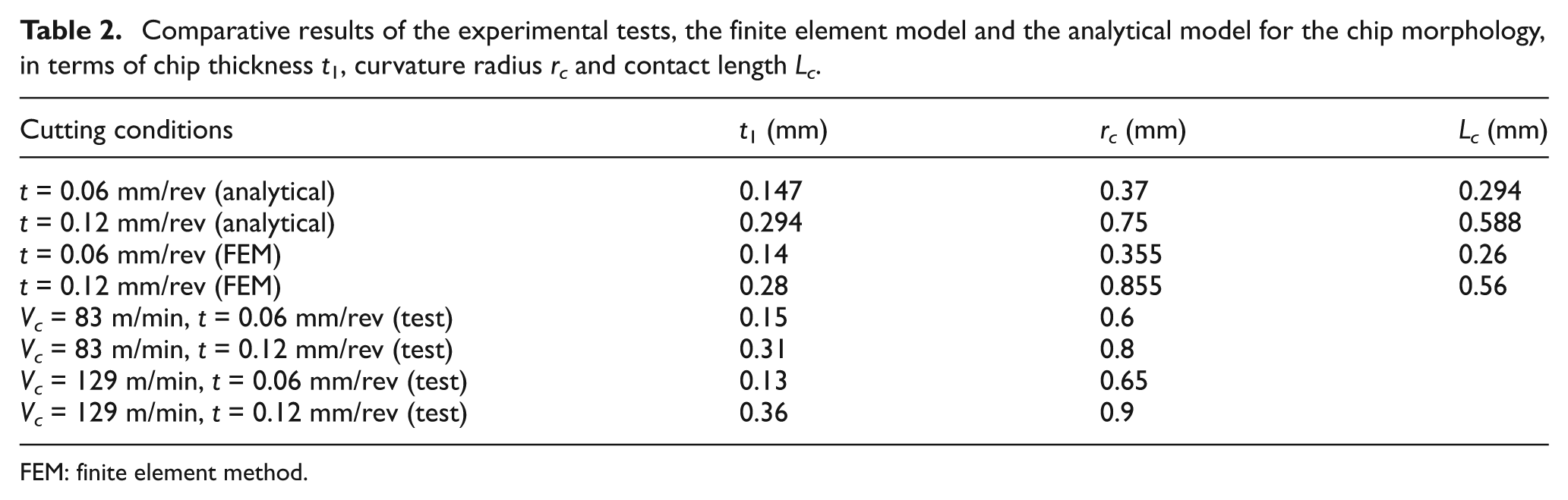
FEM: finite element method.
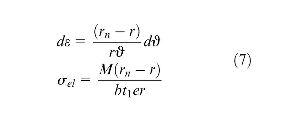
It is possible to write the stress due to a bending moment M as follows
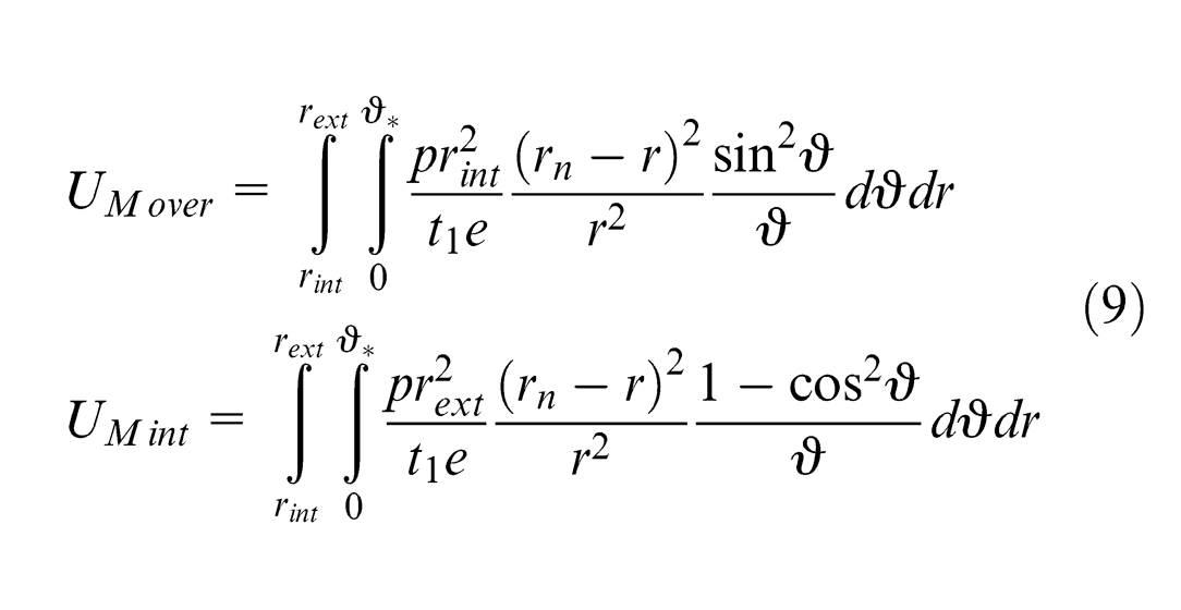
The analytical solution has to account the direction of the air jet and the projection of the component of the blowing force represented by the distributed load. It can be observed that when the jet is directed from the overhead position, the blowing force is applied only to a quarter of a circle. Equation (8) gives the moment M due to the two loading conditions as
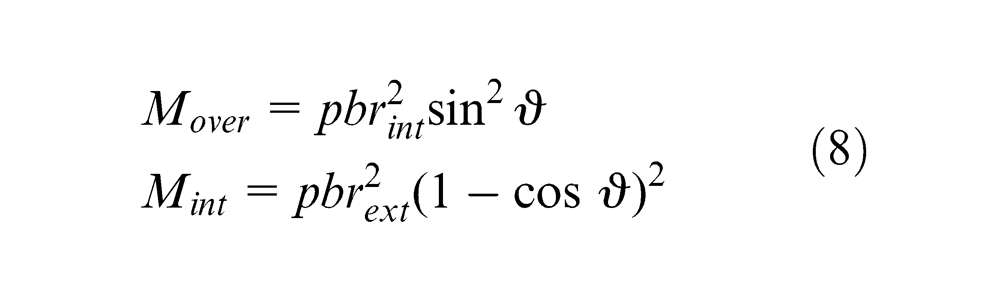
It can be observed that the solution for the moment applied in the overhead case with
The contribution has a minimum for
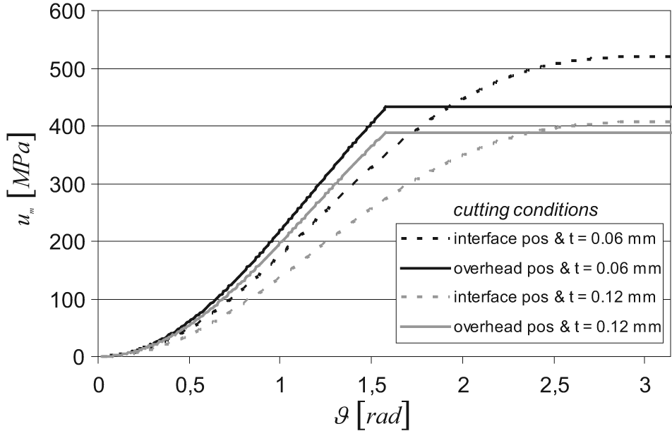
Specific deformation energy due to the mechanical effect of the air jet impinging on the chip with an inlet pressure of 7 bar.
Modeling of heat transfer by high-speed impinging jet
In order to account the cooling action of the air jet, the heat dissipated by the air jet has to be evaluated for both positions of the jet. Equation (10) represents the rate of heat uh dissipated by forced convection for unit of removed material
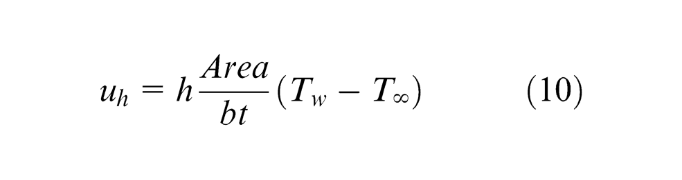
where h is the heat transfer coefficient, Area is the cooled area where the heat is dissipated, Tw is the temperature of the cooled surface and T ∞ = 7 °C is the free fluid stream temperature, measured by a thermocouple in the center of the air stream, where the conditions are closest to an undisturbed stream. The section of the air cone pattern of the air jet is much wider than the Area, so the properties of the air stream can be considered uniform. In order to evaluate uh , the Nusselt number, Nu, has to be estimated using correlations with the Reynolds number, Re, and the Prandtl number, Pr
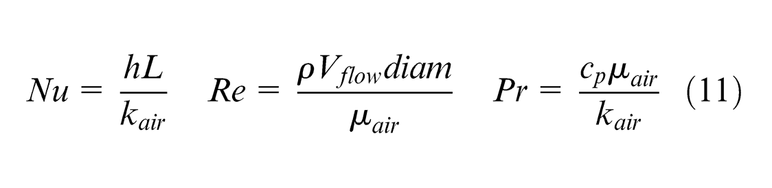
where kair, µair
and cp
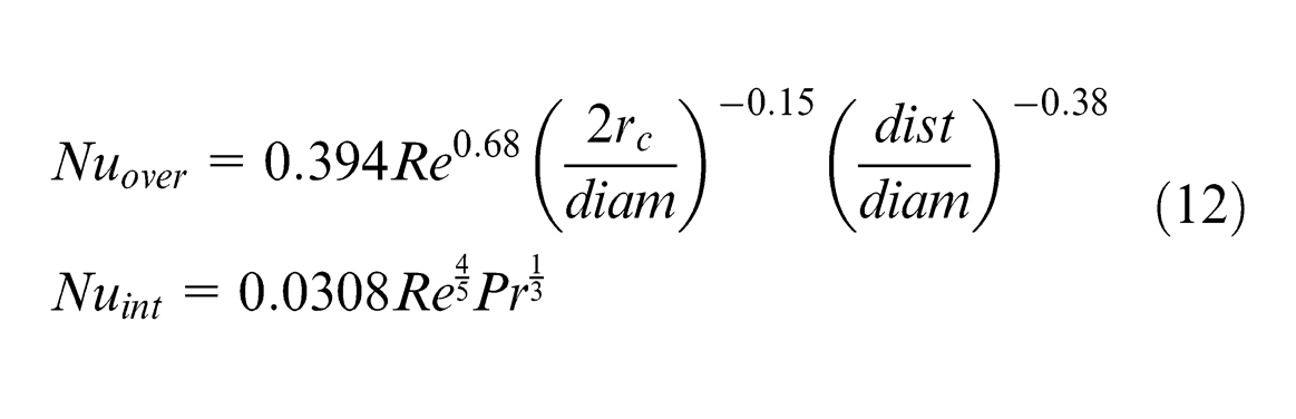
are the thermal conductivity, the viscosity and the specific heat at constant pressure of the air, respectively; L is the length of the cooled surface (in a 2D case) and diam is the diameter of the nozzle. Two results of the Reynolds number were calculated for the two inlet pressures: Re = 24,000 with an inlet pressure of 4 bar and Re = 30,000 for an inlet pressure of 7 bar. The Prandtl number for the air at 7 °C was estimated as Pr = 0.71766 for an inlet pressure of 4 bar and Pr = 0.71792 for an inlet pressure of 7 bar. Different correlations for the Nusselt number in forced convection with turbulent flow, shown in the literature review, have been compared. The correlation in the interface case is reported by Incropera and De Witt
34
and represents the Nusselt number for a turbulent flow parallel to the source of heat, evenly distributed in the chip–tool interface. Few correlations exist for impinging turbulent flow on concave surface (the chip) and on flat surface at different angles (the rake face).35–39 The number of Nusselt depends on the ratio between the distance from the concave surface and the exit section of the nozzle. If
However, finite element simulations revealed an extremely low sensitivity to the variation in h. The experimental tests carried out by Kops and Arenson 17 suggest that a suitable approximation of the local heat transfer coefficient is two orders of magnitude greater than the natural convection with air, so that a heat transfer coefficient for the air jet impinging on the chip was set to h = 2000 W/m2 K. Calculations are consistent with the choice of the order of magnitude.
Results and discussion
Figures 4 and 5 represent the comparative results of the experimental tests, finite element model and analytical model for the orthogonal cutting process with the parameters considered for this research work. The cooling conditions include the following: dry cutting and jet in overhead and interface position with 4 and 7 bar of pressure. It can be remarked that the models overestimate the experimental results. Cutting force and interface temperatures are overestimated also in the case of dry cutting. It can be concluded that this result is due to the flow stress model. In particular, the analytical model uses the same flow stress model used to represent the workpiece material in finite elements. The cooling effect by forced convection due to the air jet is also supposed to increase the flow stress of the workpiece. The same increment in the flow stress is obtained with the nozzle in both positions (overhead and interface); the difference in cutting temperature when changing the position of the air jet is not due to a thermal effect. Figure 4 shows the cutting force obtained from dynamometrical data, finite elements and orthogonal cutting model. The air jet does not have a great influence on the cutting force; however, a small increment in the cutting force is observed when the nozzle is in the overhead position. This is due to the blowing force of the air on the insert. When the nozzle is directed into the interface, the flow is almost parallel to the rake face, so no extra force is applied to the insert.
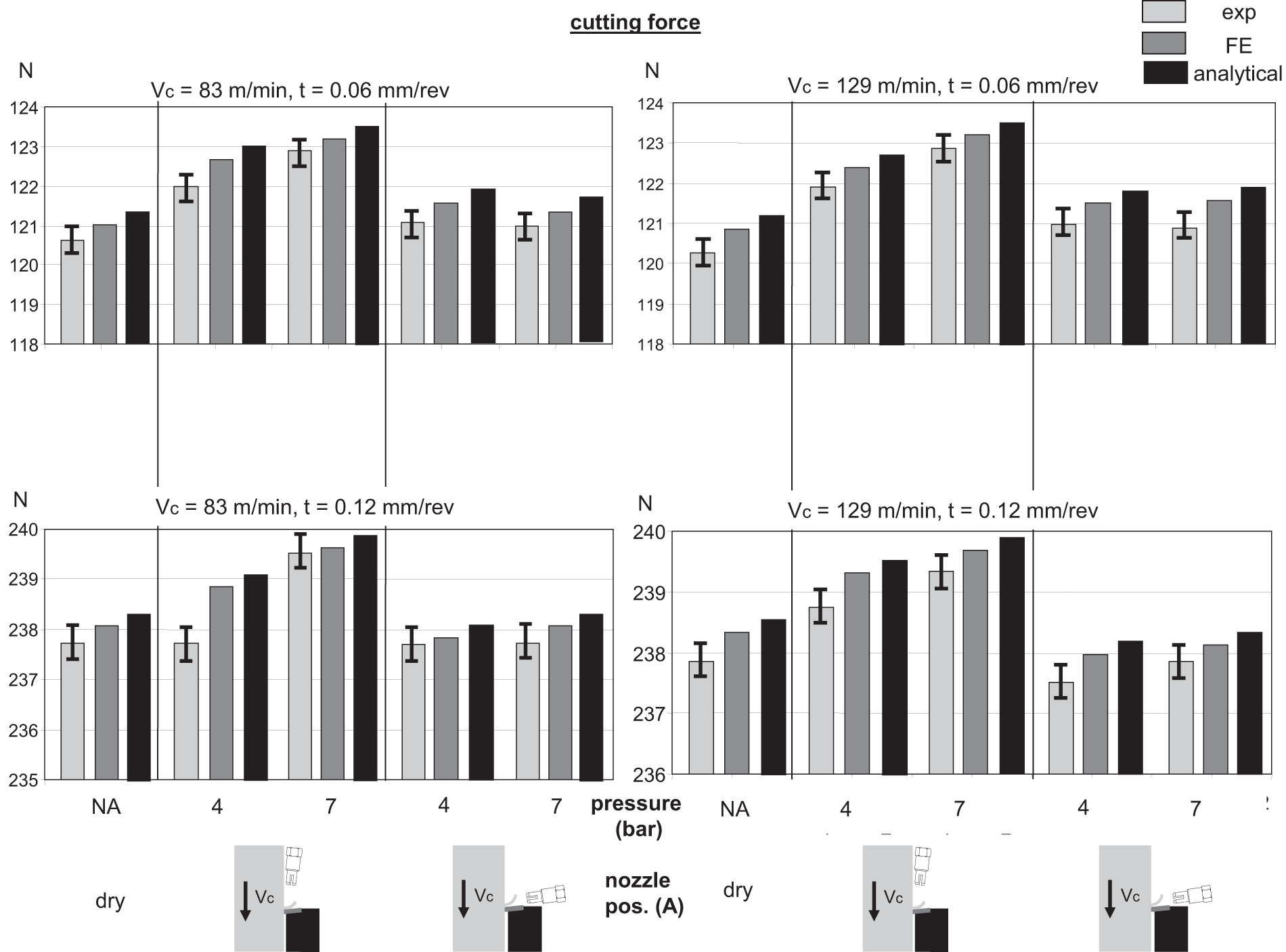
Comparative results of the experimental tests, the finite element model and the analytical model for the cutting force.
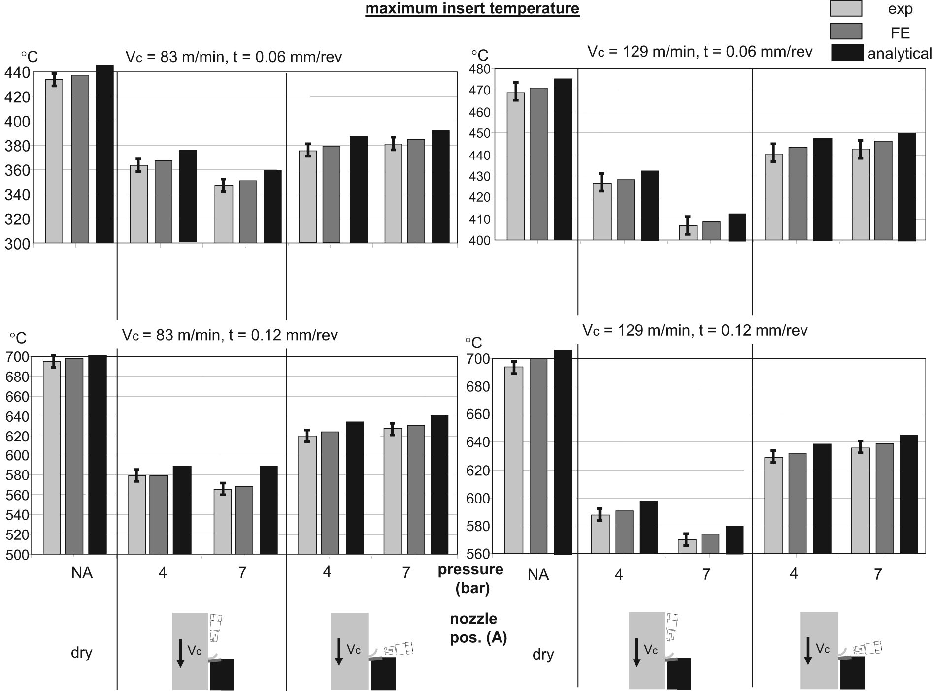
Comparative results of the experimental tests, the finite element model and the analytical model for the maximum insert temperature.
Figure 5 shows the experimental results in terms of maximum interface temperature. It can be observed that the highest temperature was measured in the case of dry cutting. Application of the air jet reduced the temperature, and the largest reduction was observed when the air jet was used in the overhead position. This trend was observed in all four cutting conditions considered.
Comparing the effects of the nozzle in overhead or interface position on the maximum interface temperature, it can be observed that the increment in pressure causes a decrement in temperature when the nozzle is in overhead position and an increment in temperature when the nozzle is in interface position. This behavior is confirmed by the analysis of the maximum effective stress on the rake face, obtained by finite elements (Figure 6). It can be observed that the maximum stress is obtained when the nozzle is in interface position with 7 bar of pressure, and the minimum stress is achieved with the nozzle in overhead position and 7 bar of pressure. Since the temperature rise by friction depends on the stress on the rake face, the optimal cooling condition is obtained when the effective stress on the rake face is minimized (jet in overhead position). Experimental investigations show that when the air jet is directed into the chip–tool interface, a small reduction in temperature is obtained in the interface due to heat transfer, but the temperature rises as the pressure increases since the effective stress on the rake face increases. When the air jet is directed on the top face of the chip, a small reduction in temperature is obtained by heat transfer, and an additional temperature fall is obtained by the reduction in the effective stress on the rake face.
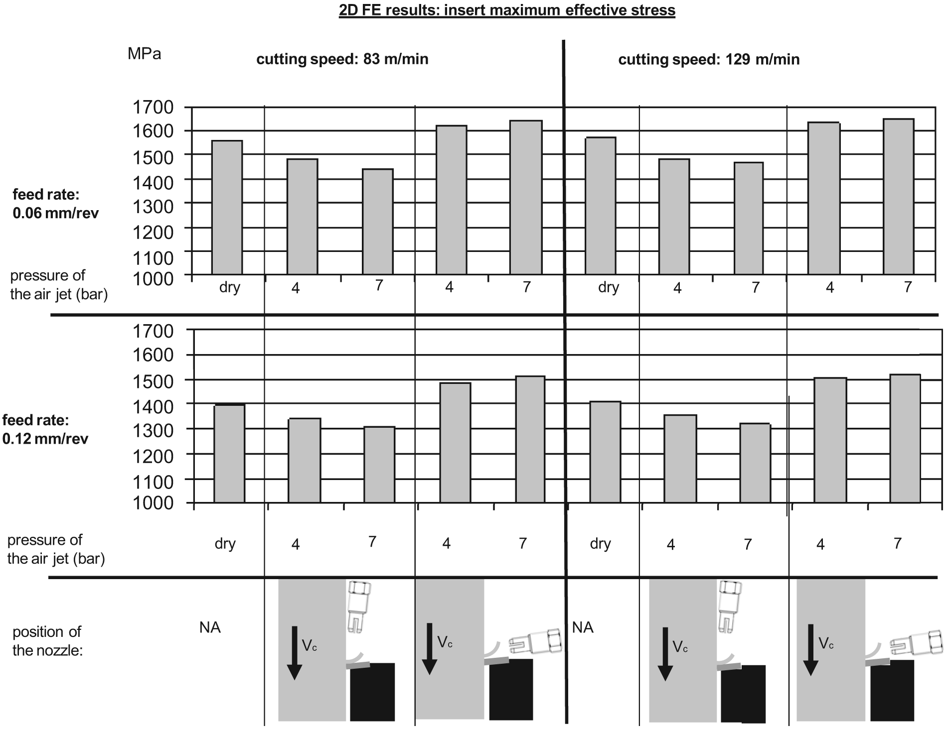
Results of the finite element model for the maximum effective stress on the rake face.
The error forks on the experimental data were obtained by the sensitivity analysis of cutting temperature to small variations in the impinging angle of the air jet, and small variation in the pressure of the air jet as well. Four positions of the nozzle were considered as follows: overhead A and B and interface A and B. From a qualitative point of view, position B, compared to position A, represents a counterclockwise rotation of the nozzle of 5°. In other terms, the angular distance between the axis perpendicular to the rake face and the axis of the nozzle is increased when passing from overhead A to overhead B and reduced when passing from interface A to interface B. The results on the left-hand side of Figure 7 show that the air jet becomes more and more efficient, in terms of cooling by mechanical effect, as its axis approaches the perpendicular to the rake face.
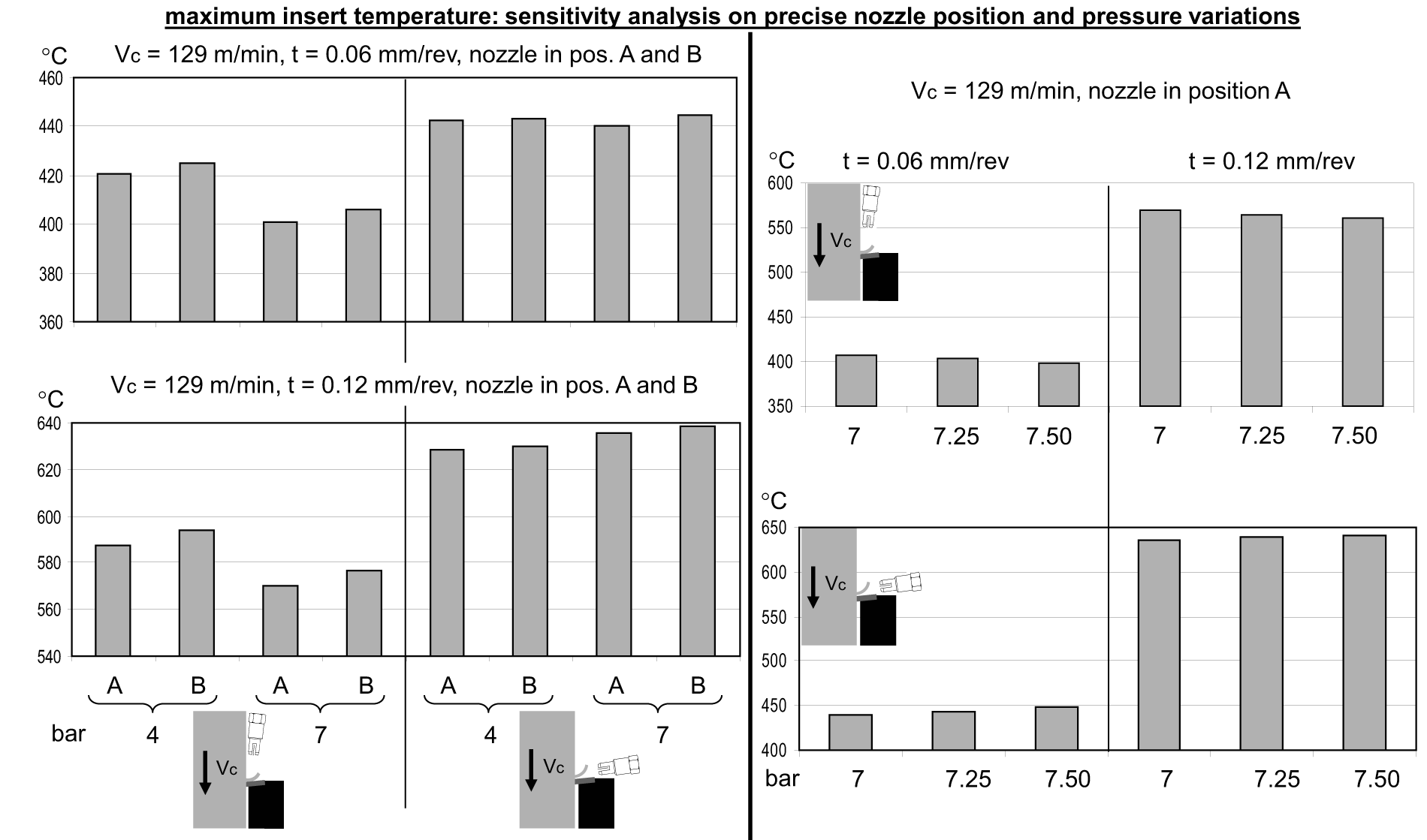
Results of the experimental tests for the maximum interface temperature. The sensitivity analysis was carried out on the nozzle position (fine adjustments) and on the air jet pressure.
The sensitivity analysis to the air jet pressure was performed with three values of pressure (7, 7.25 and 7.5 bar), as shown in the right-hand side of Figure 7: small changes in the pressure have no significant effect on the cutting force. It was observed in the preliminary measurement that when the pressure was raised from 4 to 7 bar, the increment of the blowing force was 0.8 N.
The result of this analysis shows that both positions of the jet provide cooling by forced convection; however, a temperature can be further reduced if the nozzle is the overhead position. The finite element simulations confirm the existence of a mechanical effect of the air jet during orthogonal cutting, and the analytical model provides an explanation of the phenomena. Finite element results show that the mechanical effect of the air jet alters the state of stress within the insert. By comparing the thermal analysis with the effective stress analysis on the workpiece and the insert, it can be assumed that the air jet can be considered as an external source of energy that can be used, if correctly directed, for reducing the temperature rise in the chip–tool interface. The results in terms of maximum temperature within the insert show similar trends to the results obtained by experimental tests. For all cutting parameters, the maximum temperature is achieved when the air jet is not in use. When the air jet is used, the maximum cooling is obtained with the nozzle in overhead position with the maximum pressure. These results can be explained by observing the effective stress applied by the chip on the rake face of the insert. The analytical model corresponds to the physics of the problem, and also the trends shown in the analytical modeling follow the trends of the experimental tests and finite element modeling. This provides confidence in the approach and opens the field for more in-depth investigations into particular aspects, for example, in-depth focus on finite element correlation with experimental or in-depth analysis on influence of impinging air jet on the chip all of which could form further research.
Umbrello et al. 18 suggest that the global heat transfer coefficient is influenced not only by the temperature of the contact area but also by the stress applied by the workpiece on the rake face. Following the intuition of Umbrello, the distribution of the effective stress within the workpiece and the insert was investigated by finite element analysis. The results are consistent with the intuition of Umbrello and they explain the consistent reduction in temperature when the air jet is directed from the overhead position. With these results in mind, the mechanical effect of the air jet can be considered as an external source of energy introduced in the cutting area. In the context of introducing external sources of energy, the literature review26–29 presents alternatives such as high-power laser-assisted machining (LAM) as the practical way of heating the workpiece just before the cut is taken. The main effects of this technique are the change of phase of the workpiece material in the shallow layers of the workpiece material and a beneficial alteration of the state of stress. In a broadly similar manner, the mechanical effect of the air jet is also locally altering the state of stress with a bending moment on the chip. While the effect of the air jet cannot be directly compared to the effect of LAM, it can be considered as another approach in energy-assisted machining.
Conclusion
A set of experimental tests carried out for investigating the effects of high-speed air jets on orthogonal cutting of AISI 1020 steel by a coated WC insert have been designed to provide experimental data in terms of cutting force and interface temperature, measured by an embedded K-type thermocouple. The experimental results show an increment in maximum temperature in the chip–tool interface when the pressure is increased with the nozzle in interface position and a decrement in temperature when the pressure is increased with the nozzle in overhead position. The results of the tests were confirmed by finite element analysis. Finite element analysis shows that the efficiency of air jet cooling in terms of temperature corresponds to the maximum effective stress on the rake face. This finding suggests that the mechanical effect of the air jet alters the state of stress on the rake face, and consequently the temperature rise due to friction. The results obtained by experimental tests and finite elements analysis were used to formulate a theoretical analysis and an analytical model of the mechanical effect of the air jet. The results from the theoretical analysis show that the deformation energy provided by the air jet is approximately 24% of the specific cutting energy us for an inlet pressure of 7 bar and 17% of us for an inlet pressure of 4 bar.
In conclusion, the key findings of this work can be summarized as follows:
The pressure provided by a high-speed air jet impinging on a chip produces an altered state of stress in the cutting area.
The altered state of stress has a beneficial effect in terms of cutting temperature if the air jet is directed in the correct direction (nozzle in overhead position).
Future work should address a number of areas of interest, notably the following:
Detailed finite element investigations and correlation of finite element with experimental data. This should include a detailed analysis of the sensitivity of the concept to parameter changes, tools and materials.
Detailed investigation into the fluid dynamics of the air jet impinging on the chip and in the cutting zone, with particular emphasis on fluid–solid interactions.
Economic considerations on air jet cooling in machining.
Footnotes
Appendix 1
Acknowledgements
The author would like to thank Prof. Andrew A. Torrance for his valuable support and advices.
Declaration of conflicting interests
The authors declare that there is no conflict of interest.
Funding
This research received no specific grant from any funding agency in the public, commercial or not-for-profit sectors.