
Abstract
REVO five-axis system, designed for the orthogonal coordinate measuring machines, must be reconfigured for the application in the non-orthogonal coordinate measuring machines. First, in this article, error sources of the system and components of measurement data are analyzed; then, scale values of coordinate measuring machine axes, which are essential to derive the coordinates of measured points in non-orthogonal coordinate measuring machine, are separated out. Besides, the mathematical model of REVO is established based on the quasi-rigid body theory, from which the measurement results can be evaluated by data derived instead of that returned by the system. The effectiveness of both separation of scale values and mathematical model of REVO is proved by experiments and practice. The research of this article is of great significance to the application of REVO five-axis system in the non-orthogonal coordinate measuring machine.
Introduction
REVO five-axis system developed by Renishaw is a high-efficient and accuracy measurement system. Its high-speed, high-accuracy measurement techniques offer a wide range of benefits resulting in significant throughput improvements in many fields. 1 REVO five-axis system is designed based on the orthogonal coordinate measuring machines (CMMs) and can be only applied in the same form of CMMs according to the vendor. The REVO five-axis system outputs the synthetized coordinates of the measured points to user, and data such as scale values cannot be accessed from the system. However, the scale values are of great importance for the mathematical model of non-orthogonal CMM to derive the coordinates of measured points.2–7 Then, the problem occurs in the situation where both REVO’s high-speed, high-accuracy measurement techniques and non-orthogonal CMM must be combined with each other to realize the difficult measurement task. As a result, the working and compensation principle of REVO should be confirmed clearly and definitely for the combination. In this article, REVO five-axis system is applied in a non-orthogonal CMM with a rotary axis and two linear axes, the unit of the rotary scale value is degree and the unit of the linear axes is millimeters. First, the components of measurement data returned by the system are analyzed and then scale values of CMM axes are separated out. Then, the mathematical model of REVO is established based on the quasi-rigid body theory and the coordinates of measurement point are then reconfigured, which makes it possible for the application of REVO five-axis system in non-orthogonal CMMs.
Separation of scale values
The REVO head has two rotary axes (A-axis and B-axis) and is normally mounted on the CMM quill to create a five-axis measuring system. The REVO head’s B-axis can rotate continuously in both directions. The A-axis, which is orthogonal to the B-axis, has 125° travel as shown in Figure 1.
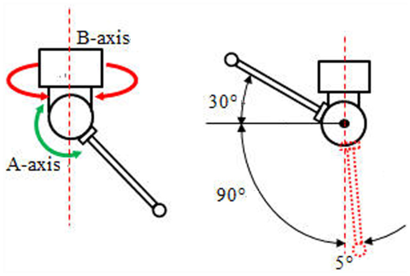
Axes of REVO head.
The output data of REVO five-axis system are the actual coordinates of the measured points in orthogonal CMM, but it is not the same in non-orthogonal CMM. The coordinates of the measured points can only be derived from the mathematical model according to parameters such as scale values, arm lengths and error motions in non-orthogonal CMM.
Components of the measurement data
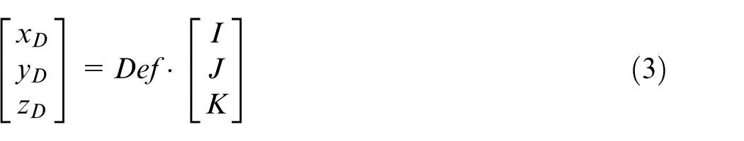
The format of the measurement data returned by the system is (x, y, z, α, β, I, J, K), in which x, y and z represent the coordinates of the measured points, respectively; α and β represent the angle values of A-axis and B-axis when probing, respectively; I, J and K represent the values of the direction vectors of the measured points, respectively. The values of x, y and z consist of three items
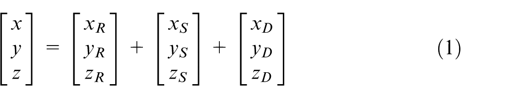
where xR, yR and zR are the displacements of REVO head motions in X-, Y- and Z-directions, respectively; xS, yS and zS are the displacements of CMM axes in X-, Y- and Z-directions, respectively; xD, yD and zD are the displacements of stylus deformation in X-, Y- and Z-directions, respectively.
It must be noted that the values of error parameters of REVO head and stylus should be set to zero in the relevant documents; otherwise, the values of error parameters will be included in the separated data.
Displacements of REVO head motions
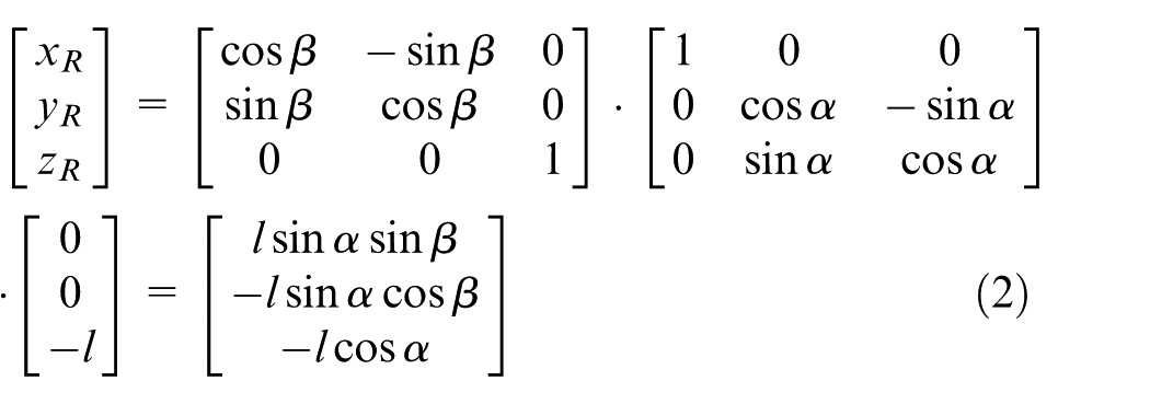
Displacement of REVO head motions, that is, the position of the tip center, is determined by the stylus length l and the rotation angles of both A-axis α and B-axis β. Without consideration of all errors of REVO head and stylus, the coordinate system of REVO head can be established as follows: X-axis is in the direction of A-axis, with the positive direction pointing outside of paper in Figure 2; Z-axis is in the direction of B-axis, the positive direction of which points up, Y-axis is perpendicular to both X-axis and Z-axis; and X-, Y- and Z-axes form a right-hand coordinate system. The origin is located at the intersection point of A-axis with B-axis, as shown in Figure 2.
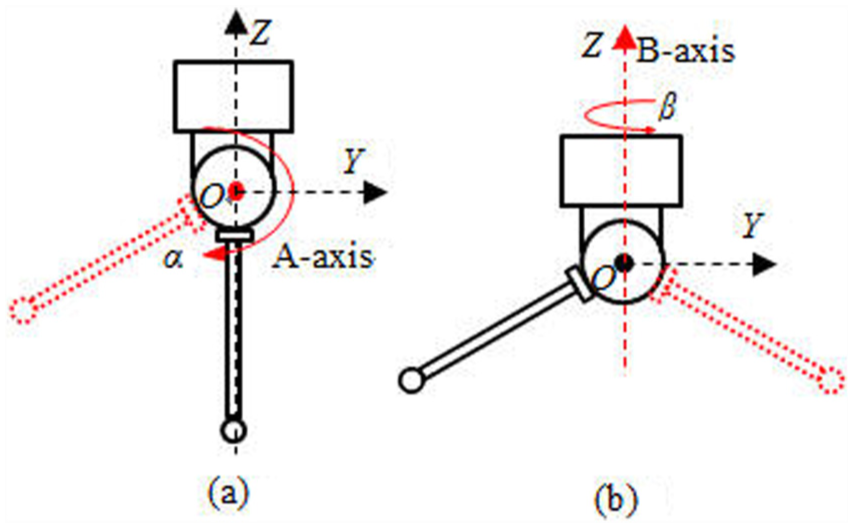
Ideal model of REVO head: (a) Defination of X-axis (b) Defination of Y-axis
Then, displacements of REVO head motions in X-, Y- and Z-directions, respectively, equal
Displacements of stylus deformation
For the traditional probe head, the rigidity of the stylus should be as strong as possible because the stylus deformation generated by measuring force will bring additional error to measurement results. As a result, the stylus length is always short enough, and then, the stylus deformation can be ignored to some extent. However, the stylus length of REVO head can be as long as 350 mm or even longer with the high-accuracy measurement unaffected as a result of the stylus compensation method as shown in Figure 3.

Compensation of the stylus deformation.
Then, displacements of stylus deformations in X-, Y- and Z-directions, respectively, equal
However, the stylus deformation is read in real time and synthetized into the coordinates of measured points with the displacements of both CMM axes and REVO head motions. It cannot be obtained from the measuring system directly. Theoretically, the stylus can be taken as a simply supported beam and the deformation of the stylus equals
Then, the scale values can be separated out from the measurement data returned by the REVO five-axis system
Mathematical model of REVO
Mathematical model provides a realistic approach to make a complete error compensation for a CMM. Establishment of the mathematical model is to set up the relationship between the output coordinates of measured points and the input parameters, such as scale values of axes, structure and error parameters. REVO head has three relative motion parts, which are A-axis, B-axis and the head; therefore, three coordinate systems which are A-axis coordinate system, B-axis coordinate system and REVO coordinate system need to be established based on the quasi-rigid body theory. Both directions of axes and location of origin of every coordinate system should be identified clearly when it is established.
A-axis coordinate system
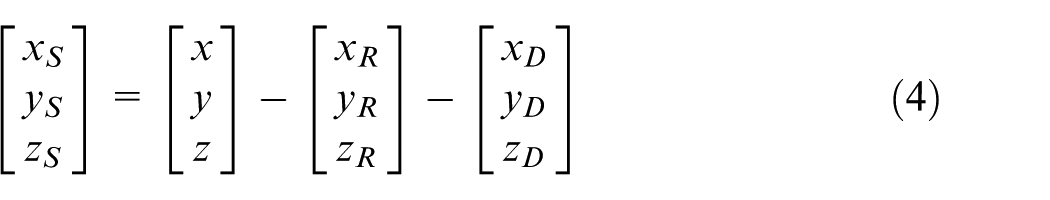
The head’s A-axis motion part consists of rotary A-axis, stylus and tip as shown in Figure 4. The perpendicular line from tip center P to A-axis is selected as the stylus direction, the distance of which is defined as the stylus length l. XA, the primary axis of A-axis coordinate system, is in the direction of A-axis, the positive direction of which points left in Figure 4. ZA is in the stylus direction, positive direction of which is from P to A-axis. YA is perpendicular to both XA and ZA. XA, YA and ZA form a right-hand coordinate system. The origin OA of A-axis coordinate system is located at the intersection point of XA with the perpendicular line from P to XA. Therefore, the coordinates of P in A-axis coordinate system are (0, 0, −l).
A-axis coordinate system.
B-axis coordinate system
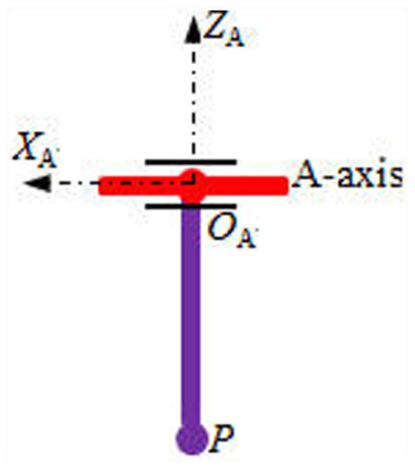
Theoretically, A-axis and B-axis of REVO should be perpendicular to each other and intersect at a point; however, it is impossible to achieve that perfect condition in the manufacturing process. In fact, A-axis and B-axis are not perpendicular absolutely and always have an offset. As shown in Figure 5, e1 represents the offset between A-axis and B-axis, which is the length of the common perpendicular between A-axis and B-axis; e2 represents the offset between the perpendicular from tip to A-axis and the common perpendicular between A-axis and B-axis; and αAB represents the error of perpendicularity between A-axis and B-axis.
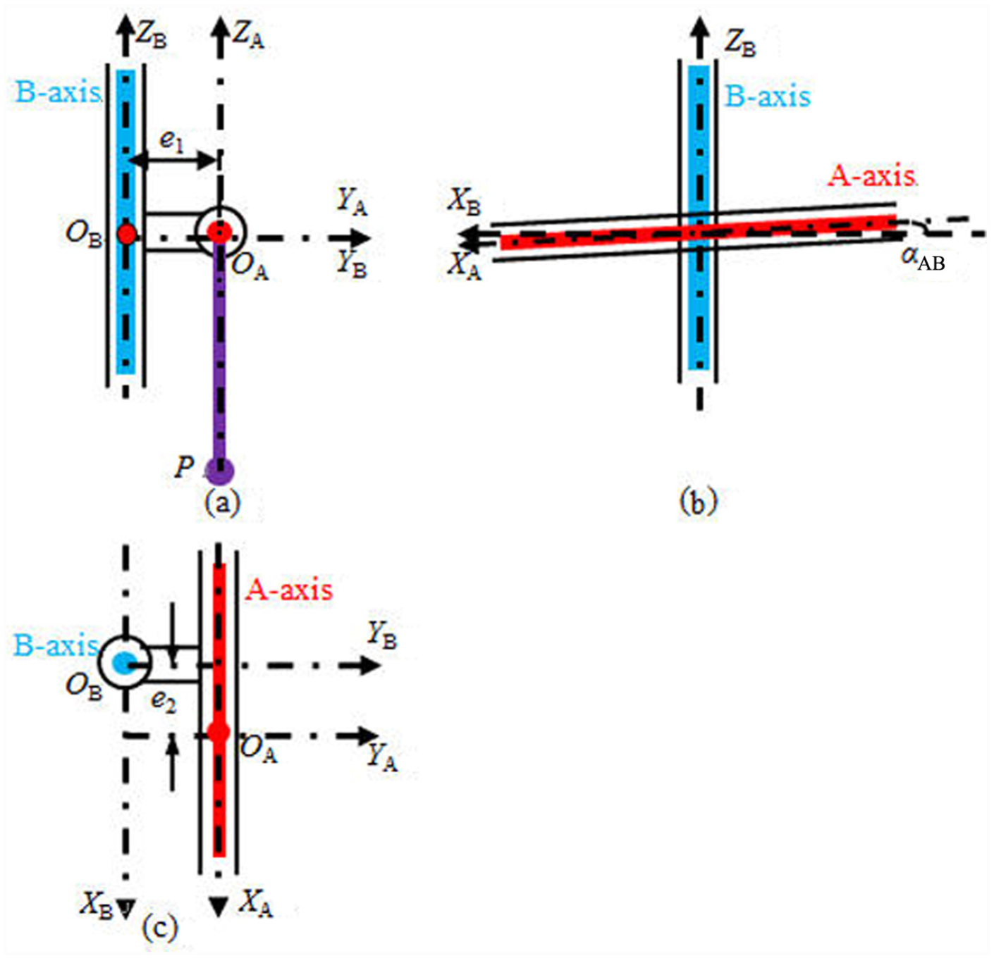
B-axis coordinate system: (a) Front view (b) Side view (c) Top view.
ZB, the primary axis of B-axis coordinate system, is along B-axis, the positive direction of which points up in Figure 5(a). YB is in the direction of the common perpendicular between XA and ZB, the positive direction of which points from ZB to XA. XB is perpendicular to both YB and ZB. XB, YB and ZB form a right-hand coordinate system. The origin OB of B-axis coordinate system is located at the intersection point of ZB with the common perpendicular between XA and ZB. For the purpose of getting the position of P in B-axis coordinate system, it is necessary to identify both the directions of XA, YA and ZA and the coordinates of OA in B-axis coordinate system. As can be seen from Figure 5(b), XA should turn a certain angle, which is the error of perpendicularity αAB between XA and ZB, around YB to be parallel to XB. The zero position of α, which is the rotary angle of XA, is defined as the position at which the stylus is parallel to the direction of ZB. At the zero position of α, YA is parallel to YB.
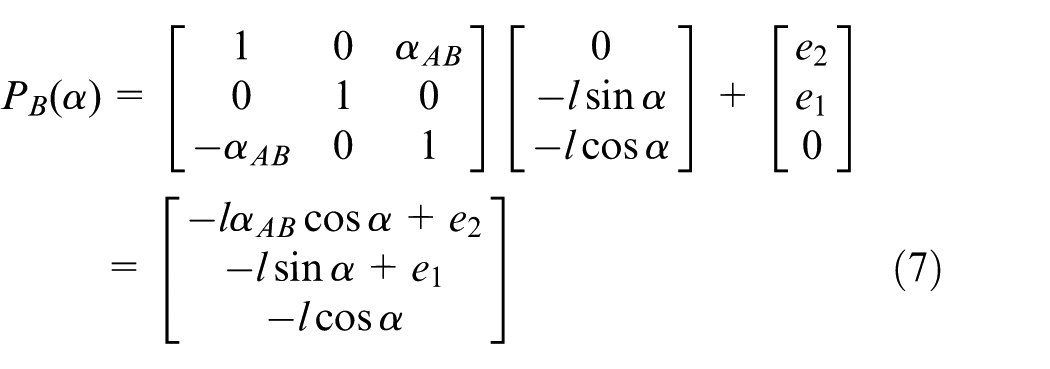
As presented in Figure 5, the coordinates of OA in B-axis coordinate system are (e2, e1, −e2αAB). And e2αAB can be neglected as a result of the values of e2 and αAB are all minor enough. So, the coordinates of OA in B-axis coordinate system are (e2, e1, 0).
When stylus rotates an angle α around XA, the coordinates of tip center in B-axis coordinate system relative to the position of α = 0° equal
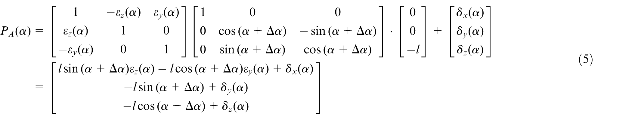
where Δα is the error motion of α; εy(α) and εz(α) are the tilt motions of A-axis around YA and ZA, respectively; δx(α), δy(α) and δz(α) are the linear error motions of A-axis along XA, YA and ZA, respectively. The high-order error is ignored during calculation.
The advanced air bearing technology is applied on A-axis and B-axis to provide a rigid measuring platform, brushless motors connected with precision encoders whose resolution are 0.08 arcsecond to guarantee the fast and ultra-high positioning accuracy. As a result, the errors stated above can be neglected, and equation (5) can be simplified as
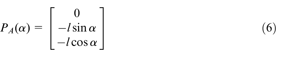
Translate the coordinate system to B-axis coordinate system, then
REVO coordinate system
β represents the rotary angle of ZB. In order to be accordance with settings of REVO five-axis system, the zero position of β is defined as the position at which the stylus points to the negative direction of Y4 when α is 90°. Unlike A-axis and B-axis coordinate systems, REVO coordinate system is stationary. At the zero position of β, the coordinate axes XR, YR and ZR are parallel to XB, YB and ZB, respectively, and the origin OR is coincident with OB. Then, the coordinates of OB in REVO coordinate system are (0, 0, 0).
When stylus rotates an angle β around ZB, ignoring the error motions of B-axis as the same reason, then
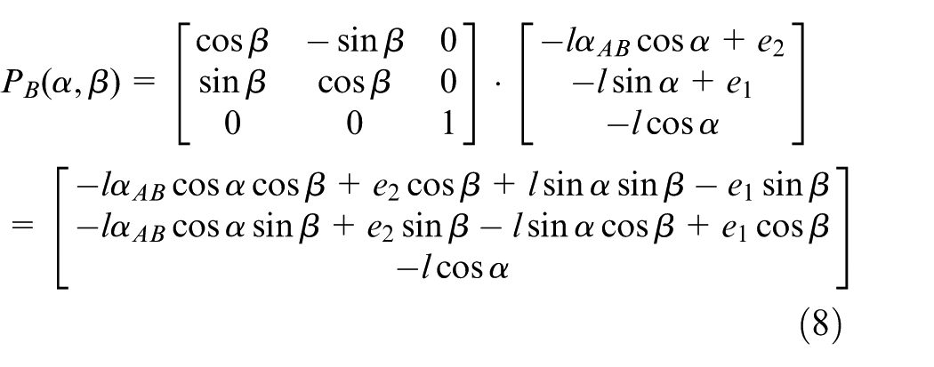
Translate the coordinate system to REVO coordinate system, then
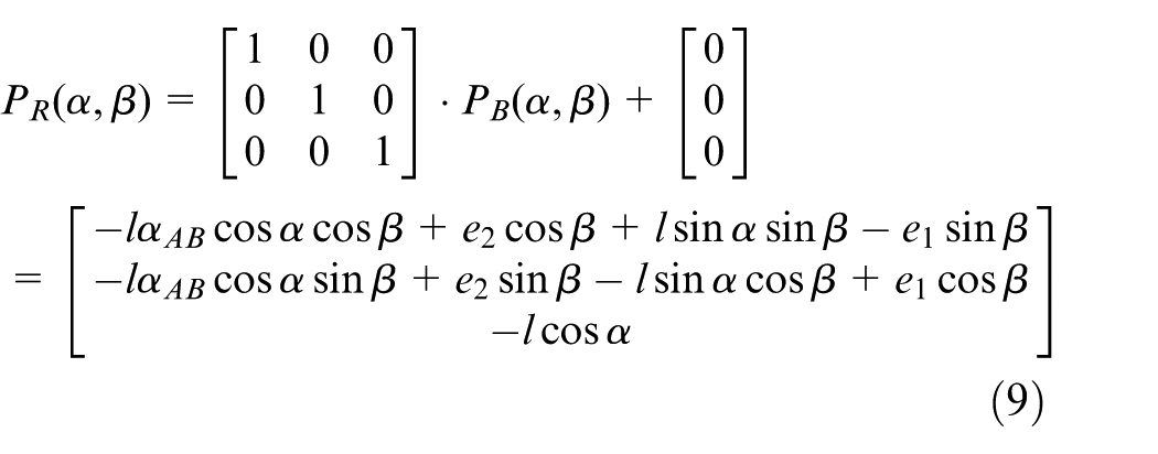
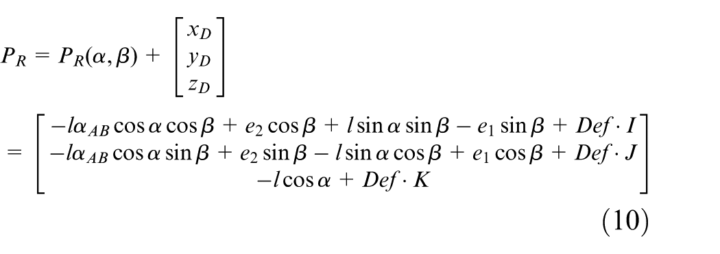
Stylus will be deflected while measuring, and the deformation will introduce displacements in X-, Y- and Z-directions, respectively. And then, the coordinates of measured points are as follows
Experiments and results
The effectiveness of the separation of scale values is proved by experiments. The gauge block is placed in different directions of working volume as shown in Figure 6.
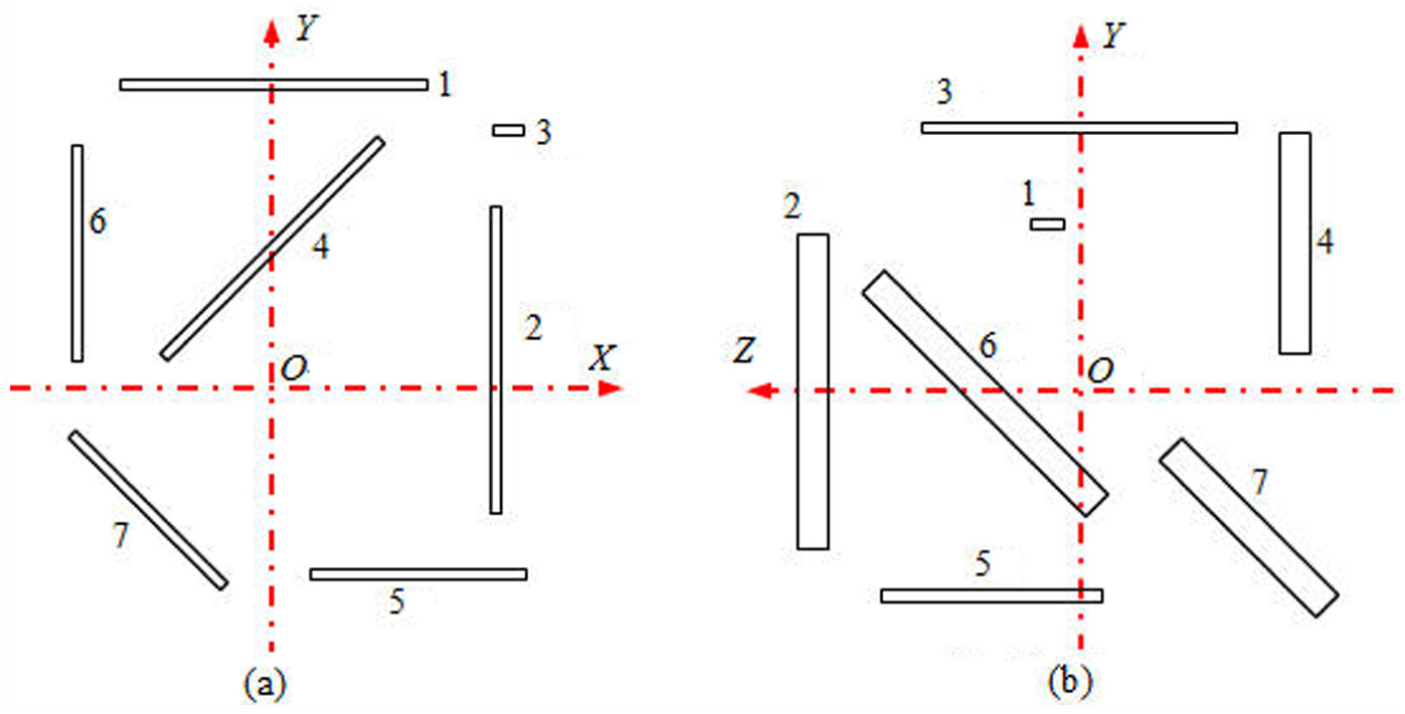
Placements of the gauge block: (a) top view and (b) side view.
At every position, the two faces of gauge block are measured by the motion of REVO while the axes of the non-orthogonal CMM stay motionless. The scale values of each axis are separated from the measurement data returned by the measuring system, and the difference of scale values is obtained at the same position, as shown in Table 1. At positions 1, 2 and 3, the gauge block is placed in X-, Y- and Z-directions, respectively. At positions 4, 5 and 6, the gauge block is placed in plane XOY, XOZ and YOZ and has an intersection angle of 45° with the X-, Y- and Z-axes, respectively. At position 7, the gauge block is placed to have an intersection angle of 45° with all the three axes.
Results of the separation of scale values.
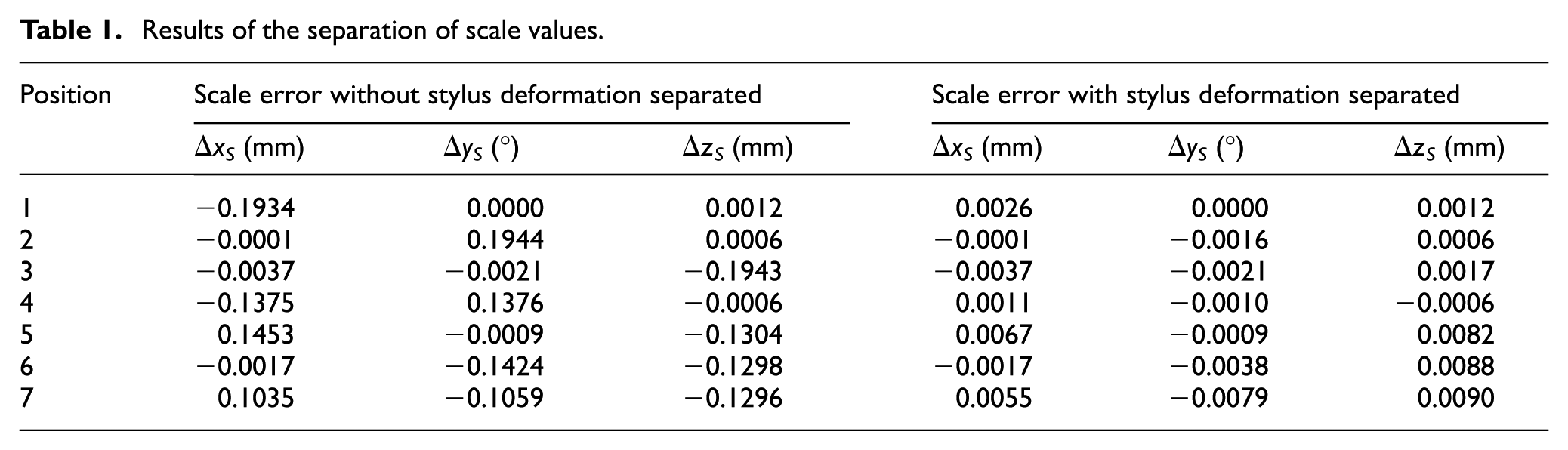
It is a fact that the scale values of every axis of the non-orthogonal CMM should be same when measuring in the condition that the axes of the non-orthogonal CMM stay motionless. As shown in Table 1, the scale values separated from the measurement data change a lot with the probe sensing direction without consideration of the stylus deformation. The absolute value of error can be above 0.19 when probing in X-, Y- and Z-directions, which is inconsistent with the actual situation. Considering the stylus deformation, the separated scale values nearly stay the same. Take position 1 and position 2 for example, the difference in scale values of X-axis and Y-axis has decreased from −0.1934 mm and 0.1944° to 0.0026 mm and −0.0016°, which proves that the separation of stylus deformation from the measurement data is valid and effective. The error values at positions 5, 6 and 7 are a little bit. The probable reason is that the stylus deformation is measured in real time in REVO, but it is derived from the measurement data based on the theory analysis and experiments in this article.
The effectiveness of the mathematical model of REVO is proved by experiments stated above. But the structure and error parameters of REVO should be calibrated beforehand.8–11 The calibration methods are discussed in detail in Li et al. 12 The evaluation results are shown in Figure 7 and Table 2.
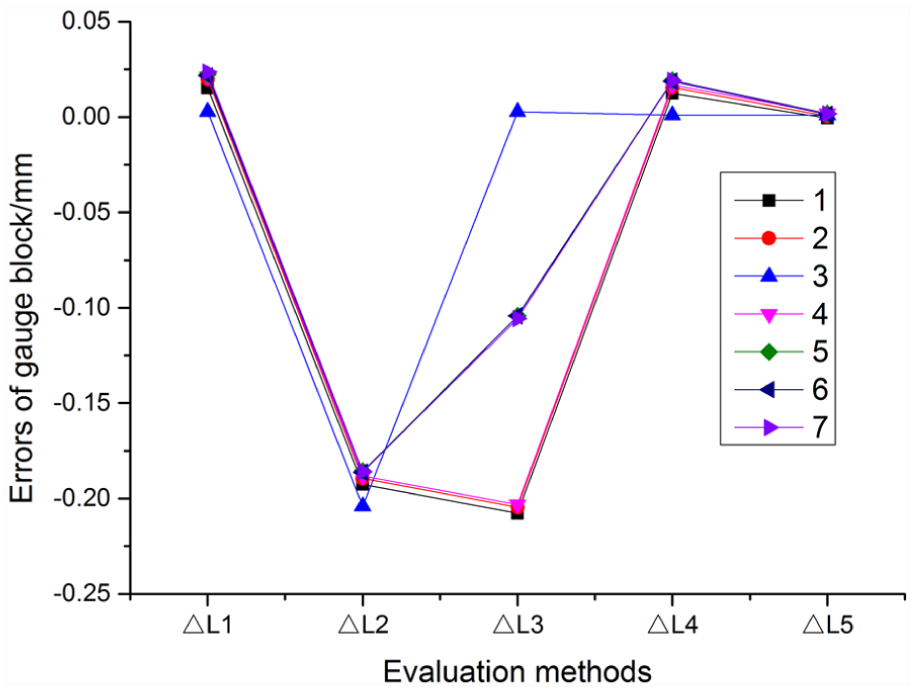
Evaluation results by different methods.
Evaluation results of measurement data.
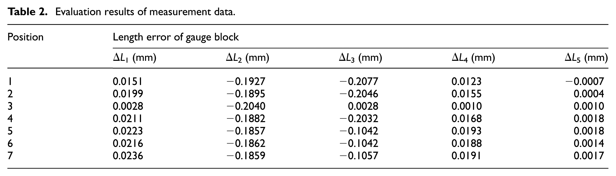
In Figure 7 and Table 2, ΔL1 represents the results evaluated directly by the measurement data returned by the measuring system. ΔL2 represents the results evaluated without consideration of both error parameters and stylus deformation. ΔL3 represents the results evaluated without consideration of stylus deformation. ΔL4 represents the results evaluated with consideration of stylus deformation only. ΔL5 represents the results evaluated with all errors compensated by the mathematical model of REVO proposed in this article.
The measurement data returned by the system can be directly used to evaluate the measurement results in condition that the axes of the non-orthogonal CMM are motionless. Without consideration of both error parameters and stylus deformation (ΔL2), the length errors of gauge block are all above 0.18 mm in seven different positions. It is obvious that stylus deformation accounts for a great proportion for the error from ΔL4 compared with ΔL2. The compensation of stylus deformation is effective from the comparison between ΔL1 and ΔL4. After compensation by the mathematical model proposed in this article, the difference between evaluation result and the truth value of the gauge block is no more than 0.002 mm in all seven different positions, which demonstrates an effective compensation effect of the mathematical model.
Conclusion
REVO five-axis system must be reconfigured when applied in non-orthogonal CMM. The measurement data returned by the measurement system consist of displacements of REVO head motions, scale values of the orthogonal or non-orthogonal CMM axes and displacements of stylus deformation. The mathematical model of REVO can be established on the basis of the quasi-rigid body model. The compensation for the stylus deformation is of great importance to improve the accuracy of both separation of scale values and measurement results. The research of this article has great significance to the application of REVO five-axis system in non-orthogonal CMM.
Footnotes
Appendix 1
Declaration of conflicting interests
The author(s) declared no potential conflicts of interest with respect to the research, authorship and/or publication of this article.
Funding
The author(s) disclosed receipt of the following financial support for the research, authorship, and/or publication of this article: This work was supported by Natural Science Foundation of Tianjin (No. 13JCZDJC34500).