
Abstract
The creation of textures and structures on contact surfaces is of importance for improving contact conditions for mating surfaces. Laser machining shows promise as a prospective technique in the fabrication of micro- and nanometre scale structures on difficult-to-cut materials. This study provides new information on manufacturing process operating variables for the use of femtosecond lasers in structuring the carbide tool rake face with a view to improving the tool–chip contact phenomena. Experiments were based on a femtosecond Ti:sapphire laser system with a wavelength of 800 nm, pulse duration of 100 fs and repetition rate of 1 kHz. The effect of laser fluence and scanning speeds on the geometry and quality of the structures was investigated. The research draws upon the requirements for cutting tools and defines the best laser process parameters to preserve the effectiveness of the carbide material in machining. This work is important for innovative development of cutting tools, alleviating critical contact conditions on the tool–chip flow faces and reducing energy demand in machining.
Introduction
Laser processing is a key technology for precision machining and micro-fabrication. 1 When laser pulse duration is reduced to an ultrashort timescale (e.g. from nano, pico and femto, that is, 10−9, 10−12 and 10−15 s, respectively), thermal damage becomes less dominant, and this favours high workpiece integrity and product precision in micro-manufacturing. However, a compromise has to be reached in selecting laser processing conditions for improving product quality against the need for reduced cycle time in manufacturing.
With the advent of femtosecond laser systems, the ability to create micro-structures in metals, semiconductors, ceramics and carbide tooling is promising. 2 The main advantages of commercially available femtosecond lasers over other pulsed lasers are as follows: negligible heat-affected zone (HAZ), high repeatability, precise control to ablate feature geometry 3 and very rapid energy interaction. Most of the femtosecond laser processing applications for micro-machining or micro-structuring fall under a category of surface features, such as grooves or holes, while other applications include surface relief and sub-surface micro-grating. 3 Some authors have explored the use of femtosecond lasers for creating patterns or structures in the form of micro-holes on ceramics (SiC, Si3N4 and Al2O3) 4 and slots on glass. 5 Features were fabricated by translating the specimen relative to the laser beam or vice versa.
The femtosecond laser surface structuring was explored for different objectives that include improving wear resistance on diamond-like carbon (DLC) coated on silicon, 6 reducing friction on AISI 440C and WC–10Co 7 and improving lubrication on SiC mechanical seals. 8 Table 1 summarizes several key studies on the machining of carbides with femtosecond lasers.
Summary of prior work on femtosecond laser machining of cemented carbide.
Information not available.
Tan et al. 9 used low fluence and moderate scanning speed and concluded that femtosecond laser ablation had no effect on the hardness of the carbide material. They further investigated the effect of laser ablation on the composition of the surface material. Through energy-dispersive X-ray analysis (EDXA) sampling, it was established that the surface material becomes considerably non-uniform with unwanted surface oxidation and high residual stresses. Tan et al. 9 suggested that an increase in stress in the tungsten carbide phase was compensated by stress relaxation due to a phase change in cobalt as the irradiance increased. Pham et al. 10 laser drilled micro-holes on cemented tungsten carbide and studied the effect of scanning speed, focus position and laser polarization on the shape of drilled holes. It was found that focussing on the surface, a low scanning speed and a circularly polarized beam resulted in less tapered holes and more round holes. Dumitru et al. 11 concluded that laser-processed carbide parts show an increase in surface functionality (e.g. tribology, optical structures and replication). Dumitru et al., 12 using a mild ablation regime up to 10 J/cm2, demonstrated that laser ablation improved friction and wear behaviour of the coated carbide surface without affecting the protective films of coated tungsten carbide.
There have also been other studies focussed on surface structuring of carbide material. It is noted here that authors referred to their work as texturing. For consistency and because these features were periodic, in this research, they will be referred to as structures. Table 2 summarizes some key research on structuring of cemented carbides. The results show that micro- or nano-structures fabricated on the carbide surface and filled with lubricant have the potential to reduce forces,13–15 material adhesion, 16 friction15,17 and wear rates in the ball-on-structured disc friction test. 17
Summary of research on structuring of carbide.
Information not available.
However, from Tables 1 and 2, a number of essential process parameters are missing, largely because the research was focussing on proof of concept rather than developing a robust manufacturing process. The aim of this article is to undertake a comprehensive study to establish a range of operating variables for femtosecond laser structuring of carbide tool materials.
Experimental details
Machining of slot structures using a femtosecond laser on tungsten-based uncoated flat cemented carbide cutting tool inserts (Sandvik TCMW 16T308 5015) was carried out using a Coherent Libra Ti:sapphire laser system. The laser has a wavelength of 800 nm, pulse duration of 100 fs, repetition rate of 1 kHz and energy of 1 mJ, with maximum power of 1 W. The TEM00 beam mode was used for this research.
Figure 1 shows the experimental set-up for the femtosecond laser used during this research. The laser beam was manipulated using a number of mirrors, and the laser pulse energy was varied using a neutral density filter wheel. The power was measured by a Gentec power meter, and measurements were taken before the focussing lens. A 15× REFLX objective lens with a numerical aperture (NA) of 0.28 and a focal length of 13.3 mm was used to focus the laser beam on to the surface of the cemented carbide cutting tool insert. The cutting tool inserts were screw mounted on a fixture on a three-axis computer numerical control (CNC) stage supplied by Aerotech. This stage was programmed to translate the insert perpendicular to the axis of the laser beam. The laser beam was focussed to a spot size of 30 and 50 µm. For each experiment run, to confirm the laser spot size, the focussed laser beam was fired on a carbide surface and then the spot size was measured by optical microscopy. This method has been proposed for measuring focussed Gaussian beam/spot size by Kiang and Lang 18 and has been used by other researchers.19–22
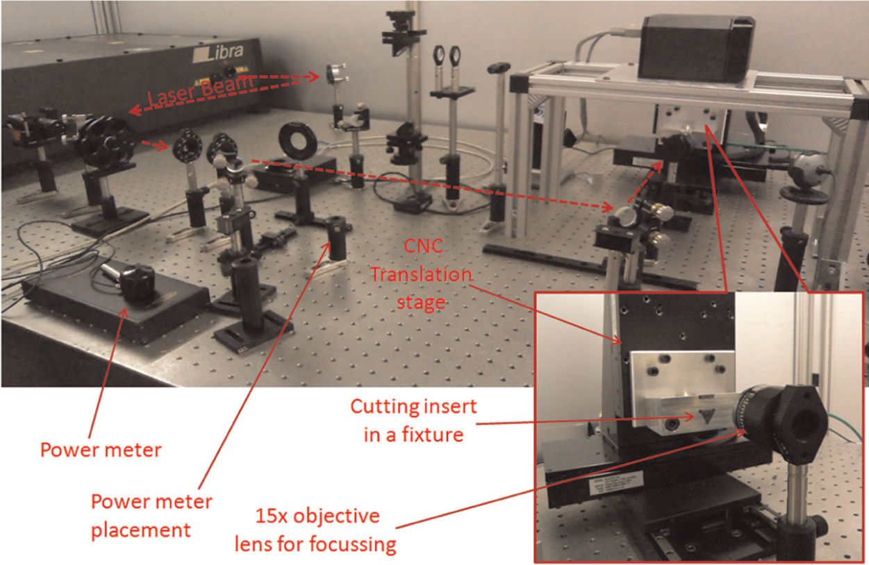
Experiment set-up.
Laser machining of cemented carbide was carried out at room temperature and pressure. Both before and after the experiments, each sample was washed with deionized water in an ultrasonic vibration tank for 8 min to facilitate removal of deposited particles. The 8-min duration was established from a pilot cleaning test as a period that gives satisfactory cleaning. Low to high fluence, ranging from 2 to 102 J/cm2, was used in these experiments. It was established through pilot tests that a fluence lower than 2 J/cm2 did not lead to material removal. The 2 J/cm2 lower end fluence is comparable to the value used by Tan et al. 9 and Dumitru et al. 11 As shown in Table 2, Dumitru et al. 11 also used a fluence of 10 J/cm2. In the interest of investigating more rapid machining, the highest fluence available for the laser power and spot size, 102 J/cm2, was used as the higher end of the window to be investigated. At each fluence, seven different scanning speeds were used (0.5, 1, 4, 6, 10, 15 and 20 mm/s). The femtosecond laser beam was used to machine a linear track in a single pass.
The laser machined geometry (kerf) was characterized using a Wyko NT1100 white-light interferometer and optical three-dimensional (3D) microscopy. Figure 2(a) and (b) shows the data obtained from the white-light interferometer for the fluence of 37 J/cm2 at 0.5 mm/s. Data obtained from such measurements were used to evaluate kerf geometry. Hardness values were measured using an MVD micro-hardness tester manufactured by Buehler. The micro-hardness variation around the kerf was used as a proxy to infer the extent of the HAZ.
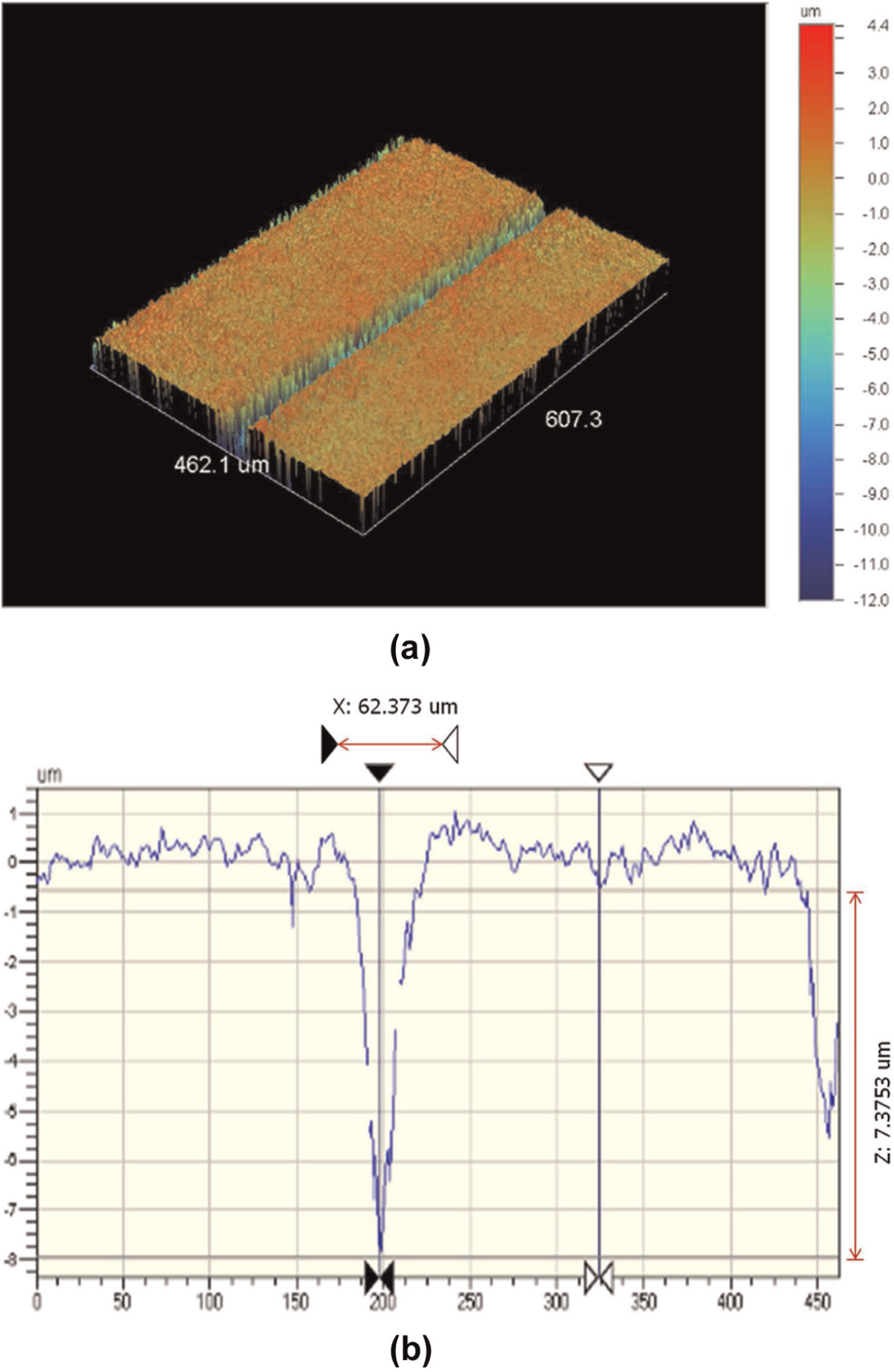
(a) 3D white-light microscopy image and (b) cross section through the laser kerf (kerf width = 62.373 µm and kerf depth = 7.3753 µm).
Results
Kerf width
Figure 3(a) and (b) shows the variation in top kerf width with the fluence (energy density) for different scanning speeds for 30- and 50-µm-diameter laser beam spot sizes, respectively. For both spot sizes, the kerf width was found to increase almost linearly with higher fluence and reduce with increasing scanning speed. This is logical because with high fluence and low laser scanning speed, more energy is delivered and the interaction time is longer. From Figure 3(a), two different regimes are evident in that data for the 20, 15 and 10 mm/s scanning speeds are closer together compared to processing in a lower scanning speed regime between 0.5 and 6 mm/s. For higher spot size, the two regimes are less distinguishable.
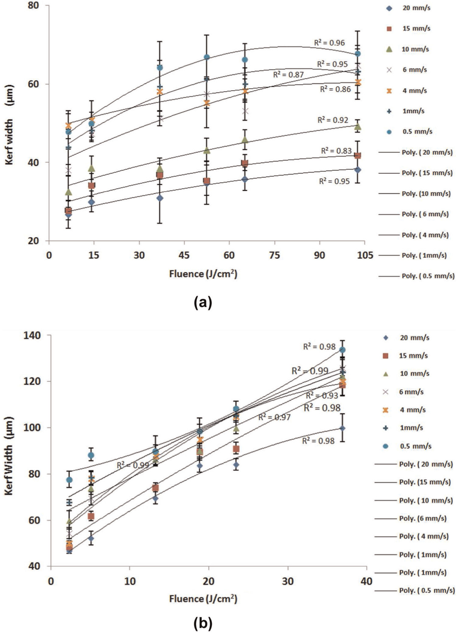
Variation in kerf width with fluence at different cutting speeds for a spot size of (a) 30 µm in diameter and (b) 50 µm in diameter.
Depth of kerf
The effect of fluence at different scanning speeds on the kerf depth is shown in Figure 4(a) and (b). It can be seen that the depth of kerf increases with fluence and reduces with scanning speed. This trend is similar to the kerf width and hence driven by the same principles. Owing to the TEM00 mode, a smaller spot size has a higher beam intensity and is therefore concentrating energy flux, resulting in a deeper penetration into the material. From Figure 4(a) and (b), it can be recommended that if deeper structures are required, the smaller spot size Gaussian beam, higher fluence and minimum scanning beam should be selected, provided this does not compromise the surface integrity of the material. From Figures 3 and 4, it is clear that the geometry of the machined kerf is more predominantly influenced by the scanning speed than the changing fluence. This suggests that thermal coupling is a significant factor in defining the geometry of the slots. This observation highlights the importance of exploring a wide range of processing conditions if the goal is to customize the geometry of slots for different applications.
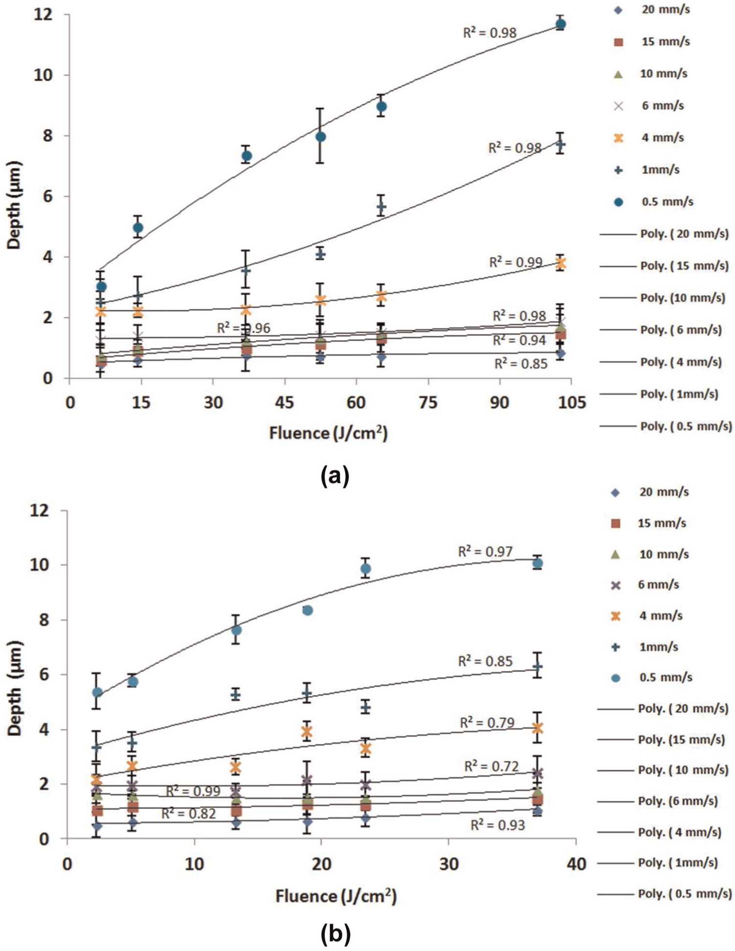
Variation in kerf depth with fluence at different cutting speeds for a spot size of (a) 30 µm in diameter and (b) 50 µm in diameter.
Surface roughness
When structuring is performed on tooling, the surface roughness inside the kerf or on the pitch islands can be critical for the performance of the product. To assess the impact of femtosecond laser machining on surface roughness, the surface roughness was measured within a distance of 135 µm on the side of machined kerf. Results are shown in Figure 5(a) and (b). Figure 5(a) shows that the surface roughness decreases as the scanning speed is reduced from 20 to 15 to 10 mm/s. When the speed is further reduced to 6, 4, 1 and 0.5 mm/s, the surface roughness deteriorates and is worse than at the three higher speeds. On this basis, it is clear that the use of 10 mm/s gives the best conditions in terms of reducing deposits on the side of the channels. This is comparable to 0.181 µ Ra, the average measured surface roughness on the rake face of the cutting insert prior to laser machining. The variation in surface roughness is due to the presence of debris and formation of a recast layer of molten material on the kerf edge (Figure 6(a)).
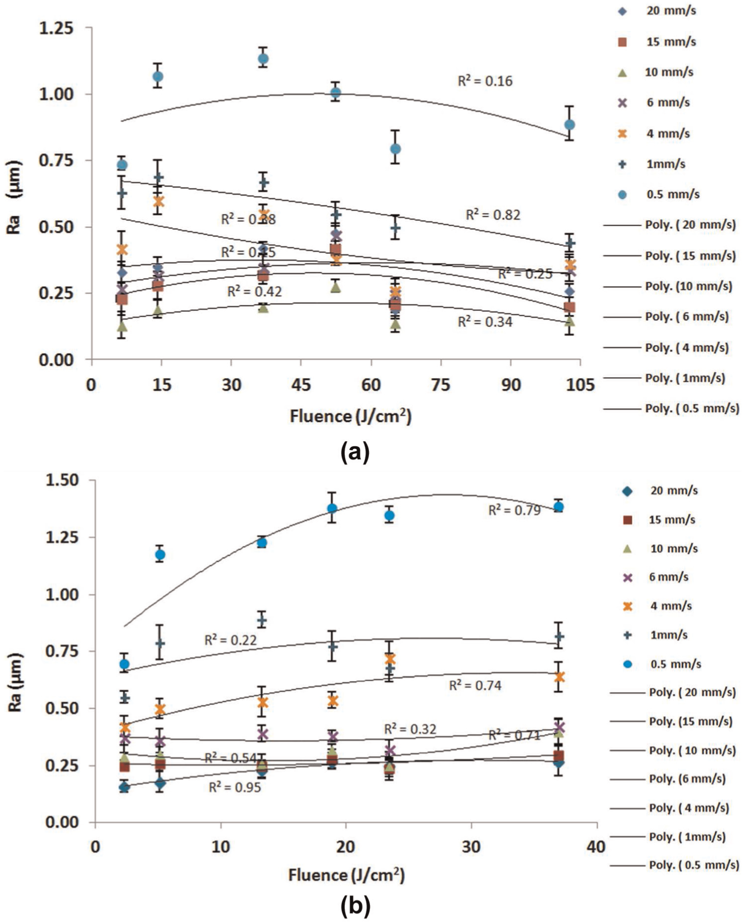
Variation in surface roughness with fluence at different cutting speeds for a spot size of (a) 30 µm in diameter and (b) 50 µm in diameter.
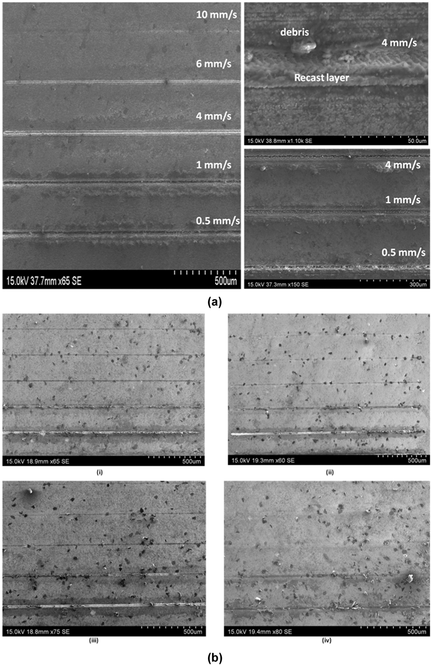
(a) Surface qualities at a fluence of 37 J/cm2 for different speeds for a spot size of 50 µm in diameter and (b) surface qualities at a fluence of (i) 102, (ii) 65, (iii) 52 and (iv) 14 J/cm2 for a spot size of 30 µm in diameter.
Moreover, it can be noted that there is a slight decrease in surface roughness as fluence was increased from 52 to 65 J/cm2 (Figure 5(b)). It is conceivable that in this range, the degree of material vaporization becomes dominant compared to melting/decomposition. According to Dumitru et al. 11 and Li et al., 23 cemented carbide material removal mostly takes place through melting and vaporization, and this depends upon the WC grains and Co binder. 11 Co binder boiling temperature lies in the vicinity of WC melting temperature. Due to the specific feature of WC–Co, Co melts and vaporizes first and material ablation occurs. This allows small WC grains to be dissolved, reprecipitated or ejected from Co melt or Co vapour. 11 However, at higher fluence, the temperature surpasses WC melting temperature, allowing materials to eject from the melt. 23 This result suggests that the selection of fluence or energy density can alter the mechanism of material removal and influence the cleanliness and quality of structured areas (Figure 6(b)). It is clear from Figure 5(a) and (b) that the improved surface quality while machining cemented carbide can be obtained by using scanning speed of 10 mm/s at almost any fluence value. A similar trend but with high values for surface roughness was obtained when laser beam size was increased to 50 µm.
Taper angle
In this study, the taper angle was measured by white-light interferometry (Wyko). The relationship between the spot size, fluence and scanning speed is shown in Figure 7(a) and (b). The value of the taper angle decreased with an increase in fluence. This occurs as a result of an increase in pulse energy density and hence improved penetration of the laser beam. For reduced scanning speed, there is more interaction time and greater opportunities for heat to widen the kerf, increasing the taper angle. On average, the taper angle was higher when a spot size of 50 µm was used compared to 30 µm. This is because the 50-µm spot has a lower average energy intensity for the Gaussian beam used in the experiments. These results suggest that using a smaller laser spot size, higher fluence and faster scanning can reduce the taper of slots machined by femtosecond laser. Larger spot sizes may be desirable for making a dished profile.
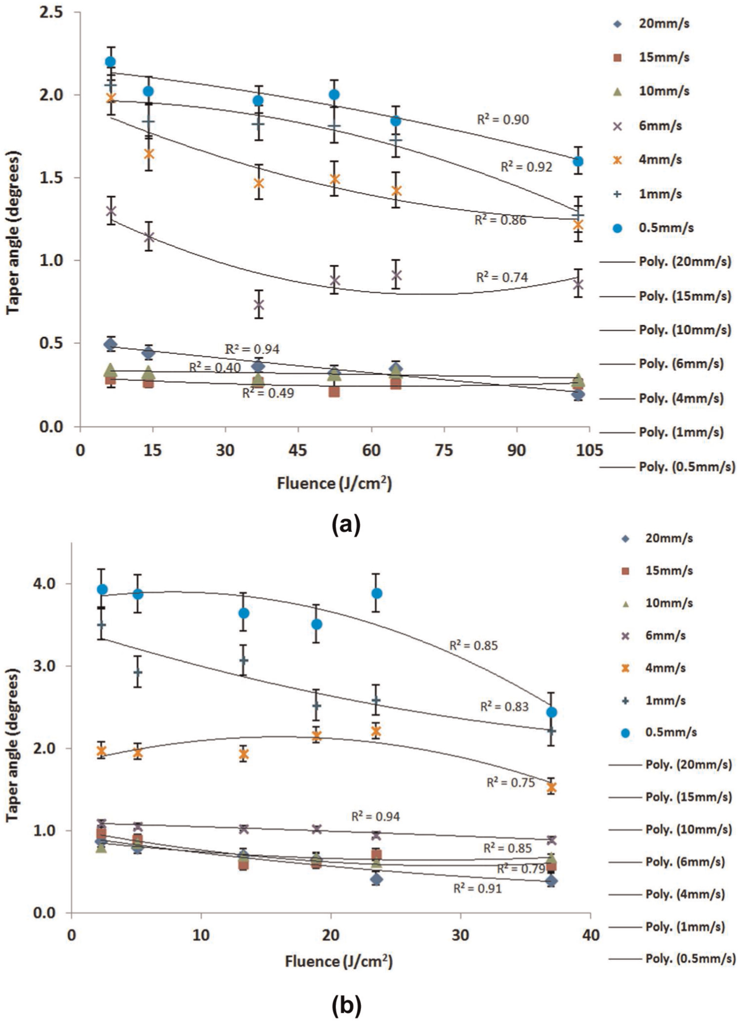
Variation in taper angle with fluence at different cutting speeds for a spot size of (a) 30 µm in diameter and (b) 50 µm in diameter.
Material removal rate
Material removal rate (MRR) was calculated by using equation (1)

where MRR is the material removal rate (mm3/min), w is the average width of cut (µm), d is the average depth of cut (µm) and v is the scanning speed (mm/s).
It can be noted from Figure 8(a) and (b) that maximum MRR is at highest fluence and lowest scanning speed. The depth and width of a laser kerf were higher at highest fluence and lowest scanning speed, respectively. Considering Figure 8(a) and (b), it can be noted that there is no significant increase in MRR as scanning speed decreased from 20 to 6 mm/s. However, there is considerably more material removed as the speed is further lowered from 6 mm/s.
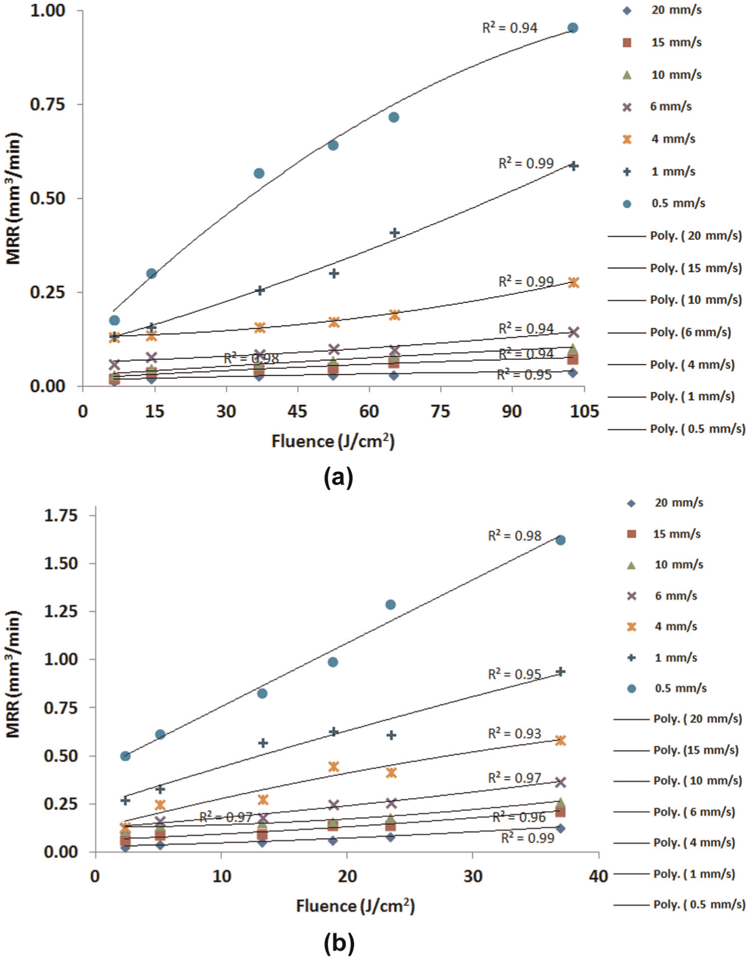
Relationship between material removal rate and fluence at different cutting speeds for a spot size of (a) 30 µm in diameter and (b) 50 µm in diameter.
Hardness and HAZ
In the laser cutting process, there is an outer periphery of a kerf which is heated but not ablated. This heated area can result in thermal cracking, change in metallurgical properties or a phase change. HAZ analysis allows any change in hardness that takes place in this area due to re-crystallization/re-solidification to be assessed. For this study, HAZ was assessed by performing micro-hardness test at 2 µm away from the kerf edge at three different locations along the cut for every experimental run.
The results obtained from the test are plotted in Figure 9(a) and (b). It can be noted that there is no significant change in hardness for almost every fluence value at high scanning speed. Furthermore, at the speed of 10 mm/s, the hardness value shows a very small change, on average (24.84–26.84 GPa) for both values of spot size. These results suggest that with high scanning speed and with ultrashort pulse (fs), the material is removed without diffusing excessive heat to the base material because of dominant material vaporization. It means that the pulse energy is predominately used to raise the temperature of material to undergo a vaporization state and produce HAZ-free results. However, as the speed is decreased, a considerable change in hardness was observed. This can be due to high thermal load and a longer duration of vapour/plasma formation that reheats the surface which in turn causes a recast layer to transfer excessive heat to the base material. 24 It was observed that the average hardness at a distance of 3.5 µm away from kerf edge was almost constant and in the range of 26.52–26.54 GPa, which is comparable to the parent material hardness (which on average was 26.53 GPa as measured on the insert before laser machining). A scanning speed of 10 mm/s does not lead to a significant compromise in reducing carbide hardness even for a wide range of fluence values.
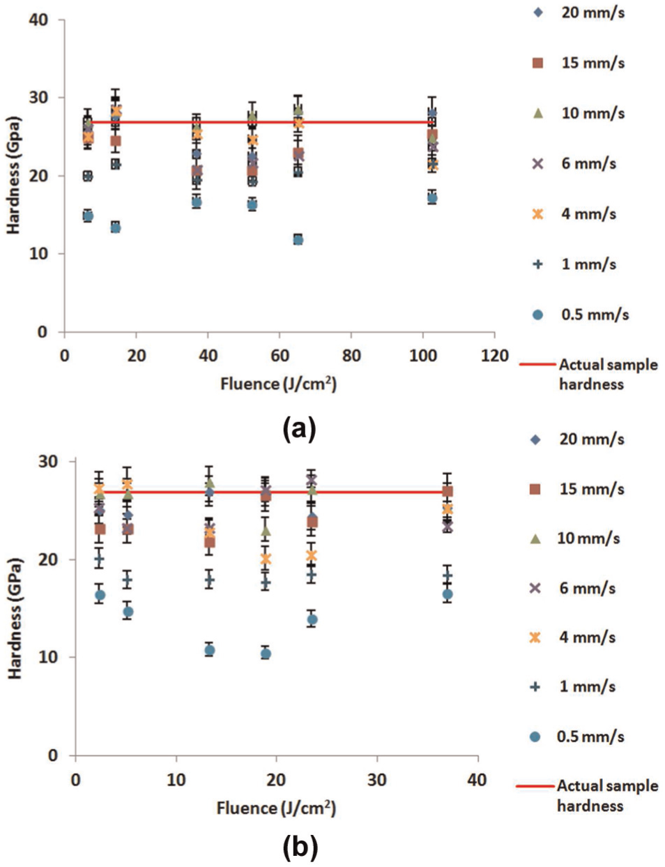
Relationship between heat-affected zone and fluence at different cutting speeds for a spot size of (a) 30 µm in diameter and (b) 50 µm in diameter.
Composition
Table 3 shows the EDXA of the surfaces before and after laser machining at different fluences for the spot size of 30 µm in diameter and scanning speed of 10 mm/s. All laser-processed surfaces show some change in oxygen content. This is expected as all the processing was accomplished without a protective atmospheric environment.
Average weight percent of elements measured by EDXA.
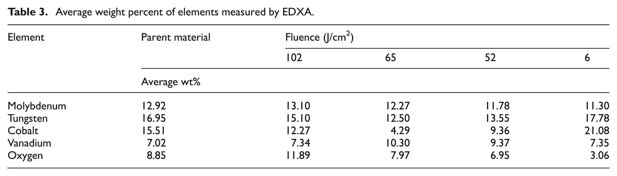
In addition, the results in Table 3 show a major change in cobalt content. It has been suggested by Li et al. 25 and Pham et al. 10 that lasers can selectively ablate cobalt from carbide material. It is possible that at 6 J/cm2, there is phase transformation that resulted in a reaction of carbon in tungsten carbide with the oxygen in the air to form gases, thus decreasing the overall oxygen content. 26 However, it is noted that data present relative percentage by weight composition. Evaluation of precise changes in element composition would require further analysis.
Case study application in orthogonal machining
One of the main objectives for developing femtosecond surface structuring is to modify the rake face surface of cutting tools so as to induce changes to tool–chip contact phenomena in machining. Based on the above performed femtosecond laser experiment, it was observed that a set of suitable parameters to rapidly create regular rectangular slot structures on the rake face are a spot size of 30 µm, scanning speed of 10 mm/s and the highest fluence. To test the application of structures in orthogonal machining, structures were fabricated on the tool rake face of the cutting tool at a distance of 300 µm from the cutting edge using above selected laser parameter (Figure 10(a) and (b)). The orthogonal cutting tests were performed on a Denford lathe machine. A Sandvik TCMW 16T308 5015 insert and Sandvik STGCR 2020K-16 tool holder were used. Forces in both cutting and feed directions were measured using a Kistler type 9263 SN 75623 dynamometer. Cutting experiments were performed on AISI/SAE4040 workpiece material, in the form of a tube with an outer diameter of 200 mm and thickness of 2.5 mm.
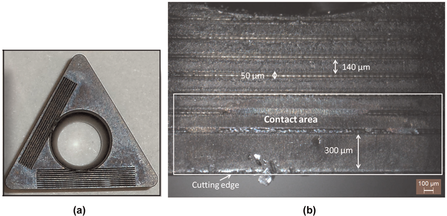
(a) Structured insert and (b) structure dimensions on insert after cutting.
The feed rate was fixed at 0.3 mm/rev while cutting velocities of 100, 198, 283 and 394 m/min were used. Length of cut was 5 mm and was kept constant for all experiments. Figure 11 shows the cutting forces experienced when machining with a femtosecond rake face structured and unstructured insert. It is clear from Figure 11(a) and (b) that rake face structuring reduces the cutting and feed forces for a number of cutting velocities. The structures provide sites for retaining cutting fluids and help improve chip flow on the rake face. Without structures, excessive pressure build up on the chip–tool interface can exclude cutting fluid access.
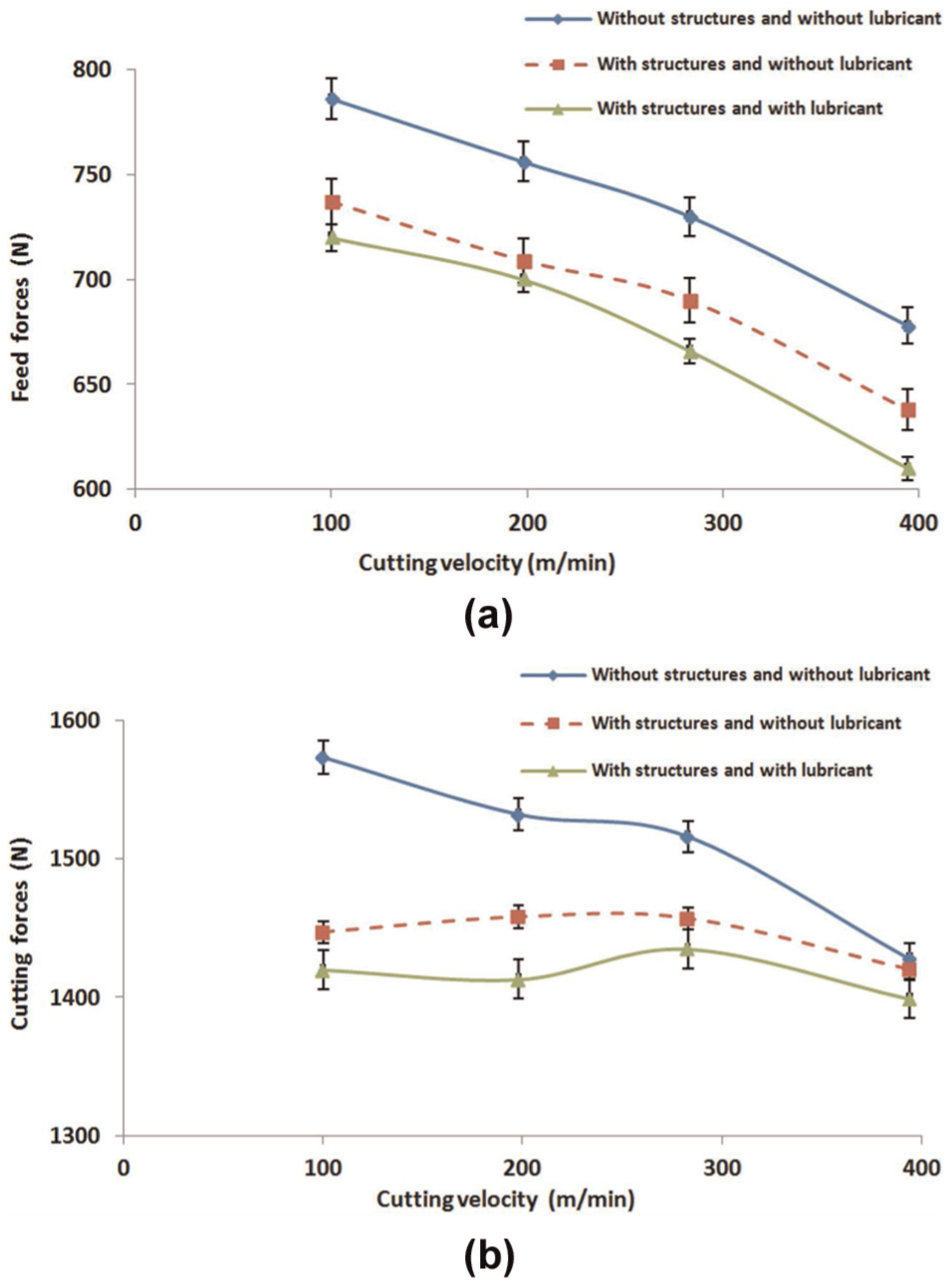
Variation in (a) feed forces with cutting velocity and (b) cutting forces with cutting velocity.
Discussion
The variation in the kerf geometry as a function of laser fluence and scanning speed reveals that the depth and the width of kerf increases with increased fluence, mainly because of increased energy input. On the other hand, as the scanning speed is increased, the depth and the width of kerf decrease since the corresponding interaction time between the laser beam and material decreases. It was noted that when structuring with higher scanning speed and at almost any fluence, the material’s micro-hardness remains almost unchanged. This could be due to the shorter interaction time associated with high scanning speeds. At lower scanning speeds, increased heat deposition to the adjacent areas promotes an annealing effect when the material cools.
The damage threshold in structuring with lasers depends on the product application. The EDXA in Table 3 shows oxygen levels, and this could be a proxy for oxidation or thermal damage. For a cutting tool, damage would occur if the effectiveness of the cutting edge was compromised. The key parameter is the hardness. The hardness of the tool has to be at least 1.5 times the hardness of the workpiece for a cutting edge to act effectively. Data reported in this article show that for all the fluences used at 20–6 mm/s, there is no significant reduction in hardness. Lower scanning speeds (4 mm/s and below) show significant reduction in hardness and this could be treated as damage.
The selection of the scanning speed of the laser beam plays a critical role in influencing slot geometry, surface hardness and surface finish. At all fluences and at scanning speeds from 20 to 6 mm/s, there was no significant change to the functional hardness required for the cutting tool and surface finish. High power and slow scanning speed lead to melt pool material deposition or an uneven surface. Choice of laser parameters is important to preserve the hardness and surface finish of the carbide tool rake face and to control kerf geometry. The machining evaluation clearly showed force reduction benefits when rake face structured tools were used.
Conclusion
This research set out to define processing conditions for rapid femtosecond laser machining of carbide tooling, to create pocket structures that can retain cutting fluid on the tool rake face and also to reduce real contact area.
The selection of laser fluence in structuring of tooling has an impact on the cleanliness of the surface. Better surface finish can be promoted by the use of higher fluence which leads to low particle deposition because of predominant material vaporization.
Changing laser scanning speed led to larger differences in slot geometry compared to setting different fluences. Thus, laser machining with a wide range of laser scanning speeds gives greater flexibility to control the slot geometry and size. This is important for different applications for the structures.
The taper of the slots machined by femtosecond lasers can be reduced by using a smaller laser spot size, higher fluence and faster scanning. Larger spot sizes may be desirable for making a dished profile.
Carbide hardness is a critical property for the effectiveness of the cutting edge. A scanning speed of 10 mm/s does not lead to a significant compromise in carbide hardness even for a wide range of laser fluence values.
Based on established relationships in metal cutting, the tool should be at least 1.5 times harder than the workpiece. For a 30-µm spot diameter, this hardness condition is met for scanning speeds of 4–20 mm/s, while for 50 µm, it was at scanning speeds of 6–20 mm/s.
The case study on AISI 4040 showed that rake face texturing can reduce cutting forces. The structures provide a fluid reservoir site and improve lubrication conditions.
Footnotes
Declaration of conflicting interests
The authors declare that there is no conflict of interest.
Funding
This research received no specific grant from any funding agency in the public, commercial or not-for-profit sectors.