
Abstract
For a number of years, the rise in the number of titanium alloy grades and therefore of microstructures has hampered the productivity of titanium parts. In order to understand the phenomena involved, this study presents a comparison of the chip formations between two microstructures obtained from the same alloy. The first part presents the two alloys, their microstructures and their methods of production. The chip formation of each material is then presented and shows two completely different processes. The first process is classical, for which shear mechanisms appear to be cyclical. Conversely, the second process depends on the orientation of the microstructure when the shear occurs. For a better understanding of the phenomena, the effect of cutting speed and feed is also discussed. Finally, in the last section, chip formations for the two microstructures are summarized and perspectives are presented.
Introduction
For many years in the aeronautical industry, the machining of titanium alloys has been very problematic due to their low machinability. Moreover, the high diversity of alloys (Ti-64, Ti-1023, Ti-5553, Ti-17, etc.) does not allow application of the same cutting conditions or the same cutting tools on all titanium alloys. Different points explain this low machinability. The first is its low thermal conductivity which is always lower than the cutting conductivity of the cutting tool material. Consequently, the temperature is directed to the tool and rapid wear occurs. The second point is the chemical affinity of the titanium alloys with the cutting tool materials, favoring the diffusion of wear and limiting the tool life. Added to this is the behavior of titanium: its high mechanical properties and its high surface integrity sensitivity. To control these points, the cutting conditions chosen are always very low, reducing productivity. Over a number of years, certain works have explored chip formation for different alloys. The first among them focused on Ti64, an α + β structure, and were conducted by Komanduri and Von Turkovich,
1
Komanduri
2
and Cotterell and Byrne.
3
These works describe chip formation in a homogeneous structure where the cutting process is never modified by material heterogeneity. Other works addressed chip formation during titanium alloy machining, with the turning of
Chip formation during Ti1023 milling when (a)
The aim of this work is to provide a comparison of the chip formation of two structures generated with the same alloy. After the experimental set-up presentation and the highlighting of differences between the two structures, the chip formation for each structure is exposed. The following section concerns the effect of the cutting conditions on chip formation and chip geometry. The relation between chip formation and cutting conditions is also explained by the Oxley model. 8 Finally, all results are summarized in the conclusion.
Experimental set-up
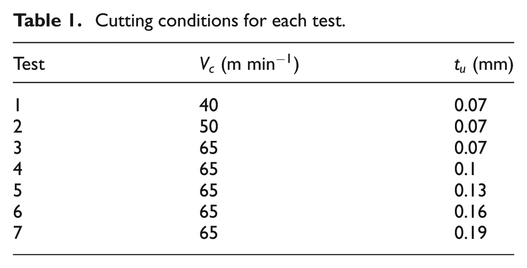
All tests have been carried out on CNC lathe Somab Genimab 900. The inserts used were CCMX 120408 with TiN PVD coating, the rake angle was 20° and inserts had a chamfer edge preparation of 0.02 mm. The tool material and geometry were classical for titanium machining. To simplify the analysis, all tests were carried out in orthogonal cutting configuration and in dry machining. The cutting conditions were defined according to the French Tool Material Pair standard 9 and they are summed up in Table 1.
Cutting conditions for each test.
The cutting forces were measured using a KISTLER quartz three-component dynamometer type 9129A. Cutting force acquisition was carried out with Dynoware software. The cutting forces are separated into two components: Fr and Fc which are, respectively, the component co-linear to the feed direction and to the cutting speed direction. All tests and all measures were performed three times and the standard deviation is often lower than 5% of the range.
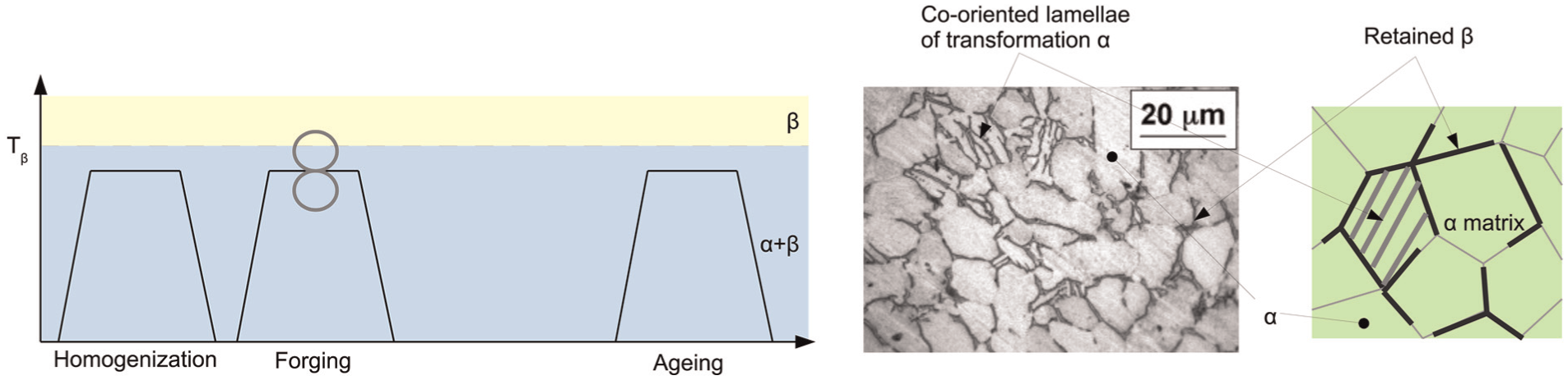
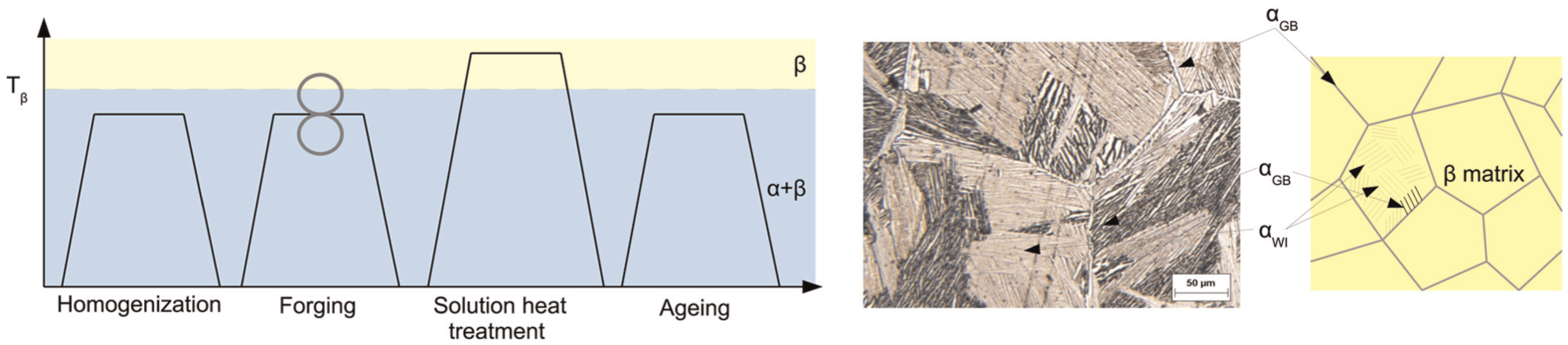
The recrystallization process comprises different steps and forms the Ti64 microstructure. Figures 2 and 3 show the heat treatment and the microstructure analysis. The aim of this section is to outline the heat treatment and the different phases of the titanium alloys obtained.
Ti64
Ti64
For this study, the classical structure is obtained with all heat treatments made below the transus temperature. As presented by Wanhill, some
In opposition, the Ti64
The mechanical properties for the Ti64
Cutting forces
First, cutting forces were compared between the two alloys (Figure 4). The monitoring of cutting forces serves to characterize the titanium’s behavior during machining. Concerning the Ti64
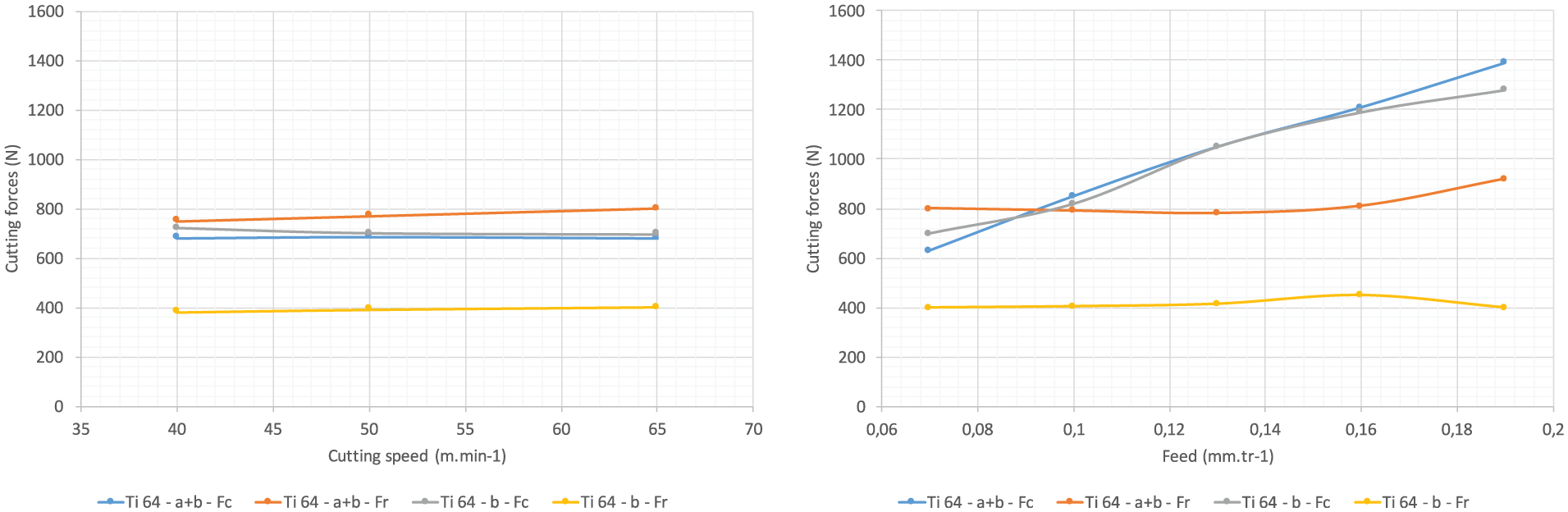
Effect of cutting speed and feed on cutting forces for Ti64
Chip formation for Ti64
and Ti64
This section focuses on the study of the chip formation. The first structure is the Ti64
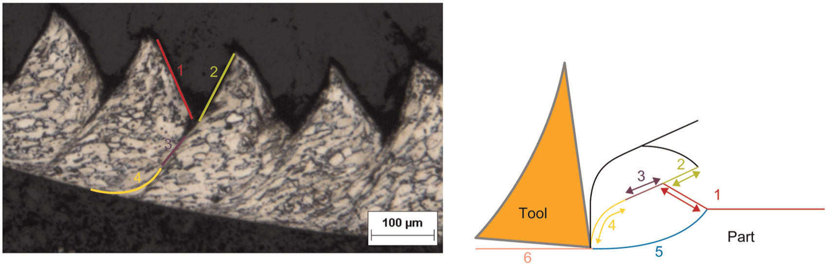
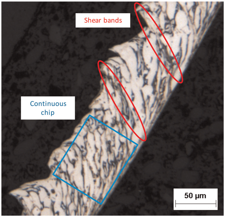
Chip formation during Ti64
The chip formation corresponds to assessments made by Komanduri and Von Turkovich
1
where the chip formation is described in several steps (Figure 5): (1) represents the chip’s undeformed surface. (2) is the
For the second structure
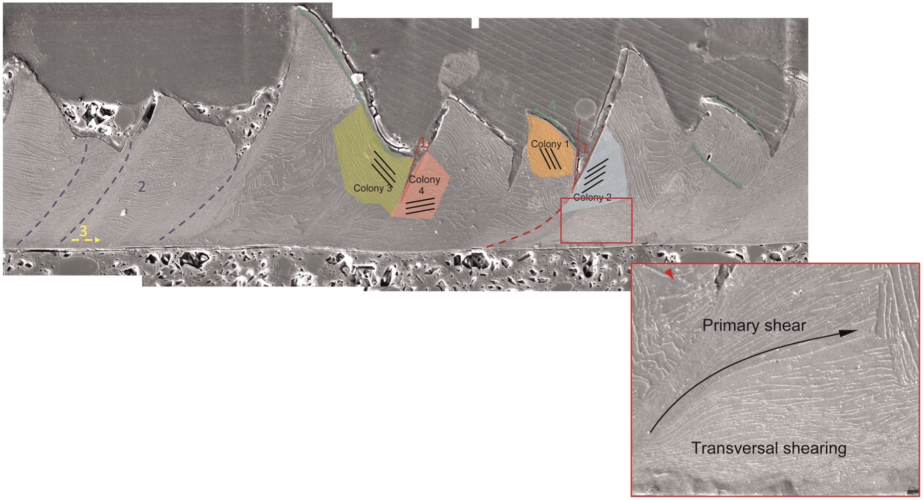
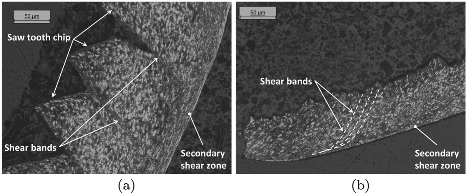
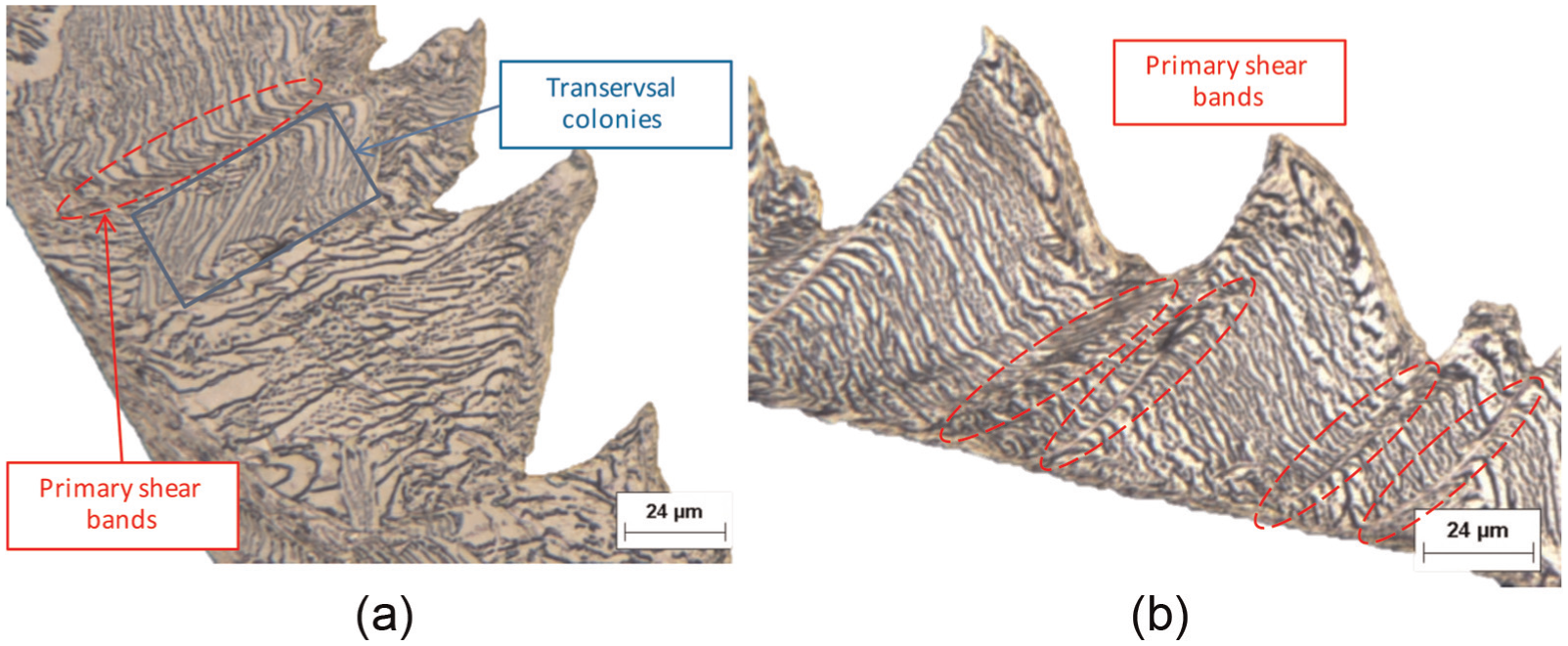
Chip morphology for Ti64
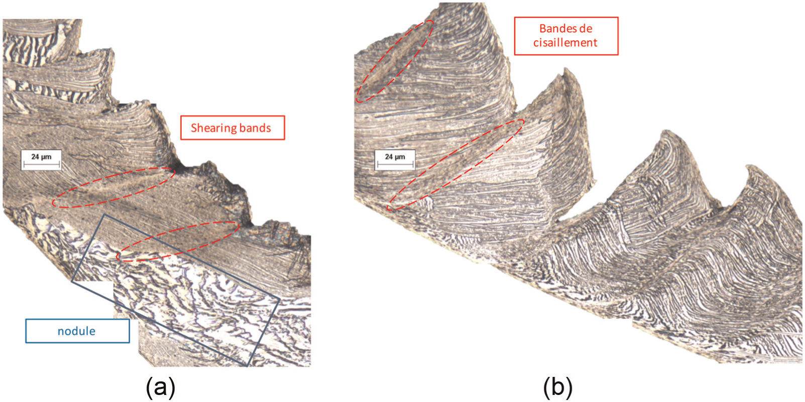
As seen in Figure 6, four configurations are identified:
First configuration. For all cutting conditions, some cracks may be created close to the primary shear band (Figure 6). Two causes are also identified. The first is comparable to the bi-modal structure
Second configuration. The primary shear bands spread preferentially through transverse colonies (Figure 6, blue zone). This preference is explained by the existing stress gradient between the different lamellae with the highest value located at the interface. So, the deformation needed to shear the interface is greater than the deformation required to shear the
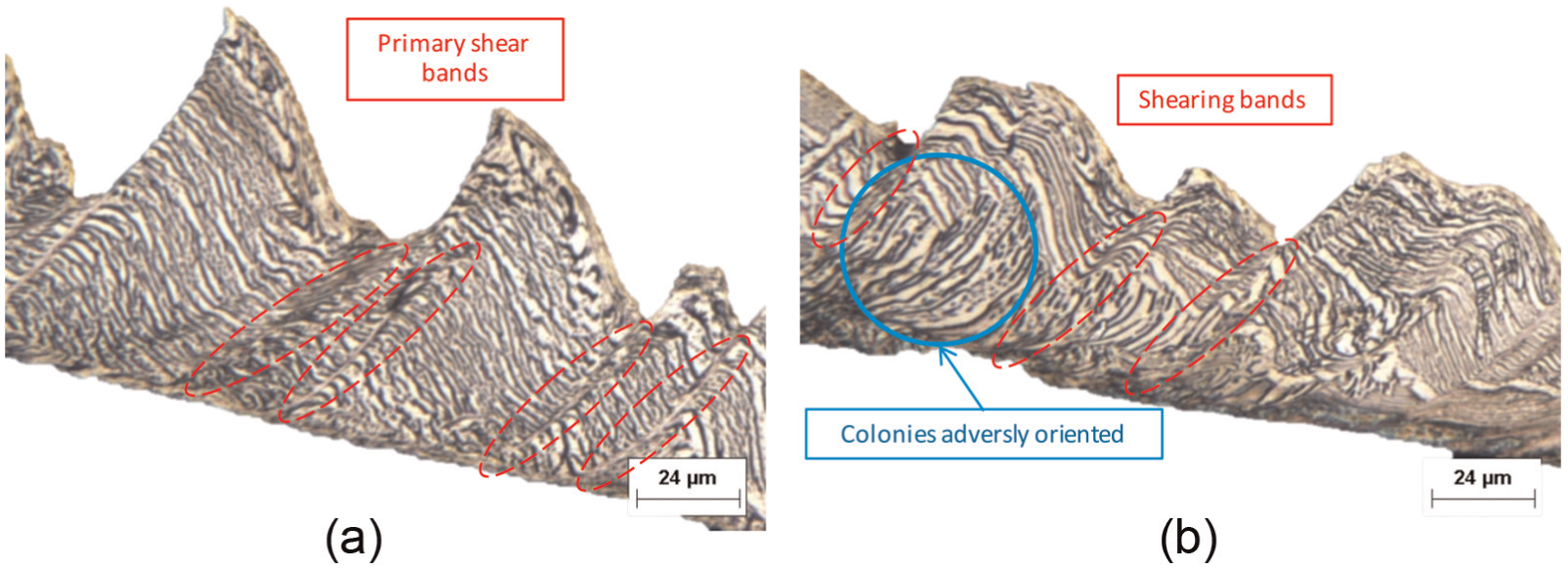
Third configuration. Transverse shear bands may occur when the colonies are co-linear to the shear band direction. This shearing is imposed by the motion between surrounding colonies. Indeed, two shearing directions are observed. The first is co-linear to the upper grain boundary, whereas the second direction is co-linear to the interface between the observed colony and the secondary shear zone.
Fourth configuration. Even though the chip formation can be assimilated to the segmented chip, a continuous shearing can still occur. This phenomenon is mainly observed near the free edge of the upper section of the chip. This shearing is explained by the motion of the highest colony (upper green arrow) and the lowest colony (lower green arrow).
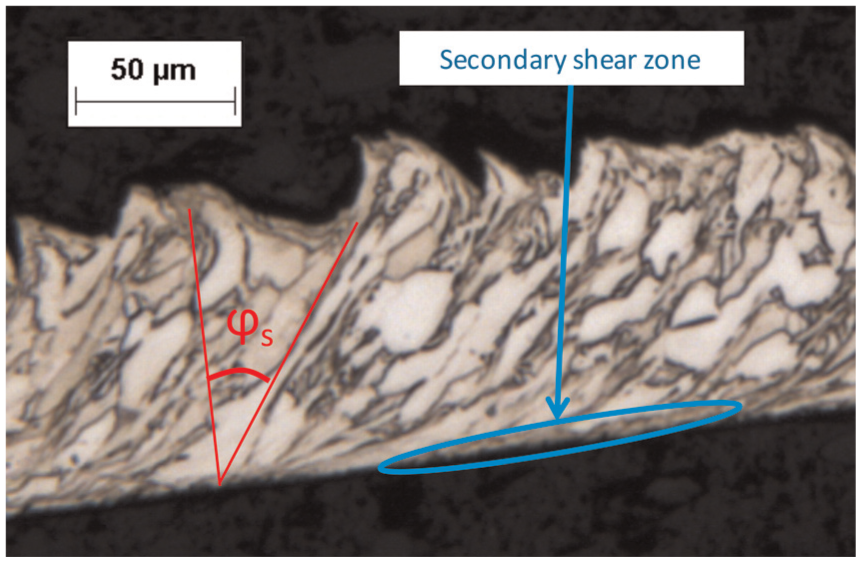
The secondary shear zone is difficult to study because the thickness is variable due to the structure. However, the phenomena observed are similar to those explained by Komanduri and Von Turkovich 1 where a strong shearing co-linear to the chip velocity is observed.
Cutting conditions effect
The next section focuses on the effect on the feed and cutting speed on the chip formation. For each cutting condition, the first analysis was carried out on Ti64
Cutting speed effect
Ti64
Concerning the
Chip morphology when
When the cutting speed increases
Chip morphology when
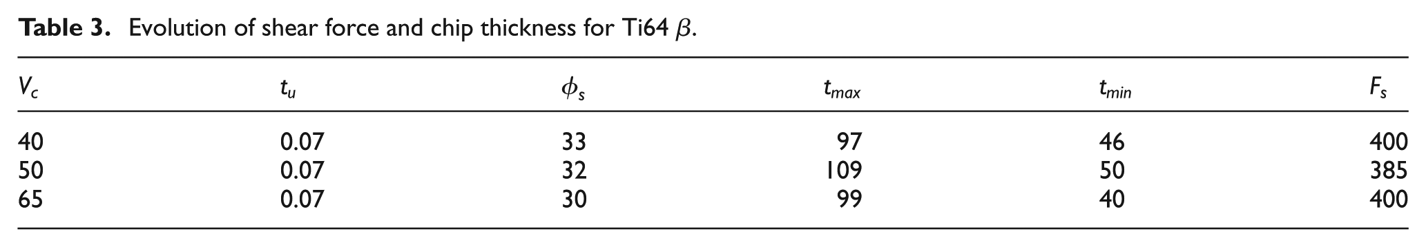
Using the Oxley model,
8
it is possible to define the shear force

Evolution of shear force and chip thickness for Ti64
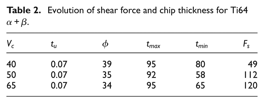
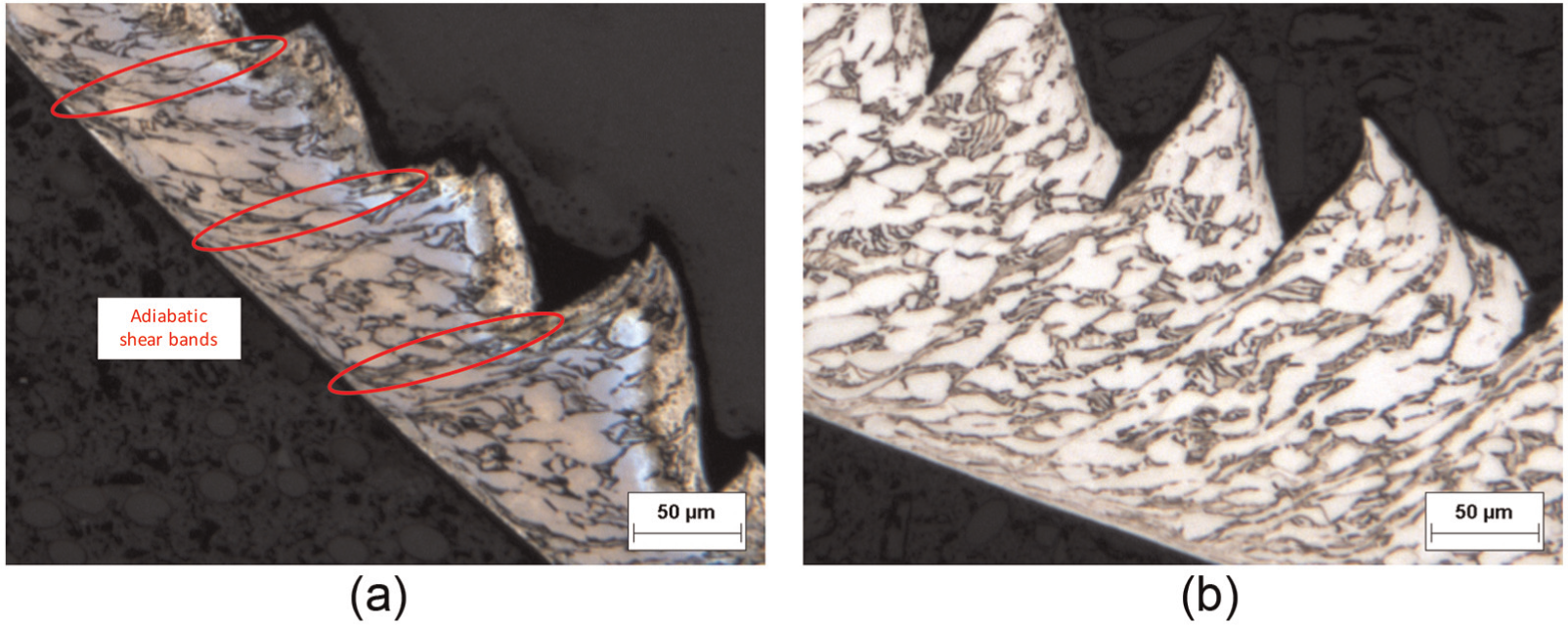
The maximal chip height (between chip base and the highest chip segment) is stable whatever the cutting speed. However, the minimal height decreases drastically between 40 and 50 m min−1. Indeed, adiabatic shear bands occur and generate some segments in the chip. 1 The minimal length evolution is also due to two phenomena:
The deformed segments (mostly sheared), which is a function of the shear band formation frequency;
The intensity of cracking formation due to the compression which occurs under the surface to be machined.
Consequently, between a continuous chip and a segmented chip, the minimal height decreases. Between two chips segmented with different cutting conditions, the height increases with shear band frequency. It should be noted that this supposition must be considered only when the cracking mechanisms are the same (same cutting forces, as in this study). The segment formation is explained in Figure 9. Point A, located initially at the intersection between the chip roots and the alloy (at the free surface), moves when the tool feeds (a) and some segments occur in the chip (b and c). When the frequency of adiabatic band formation increases, the minimal height of the chip
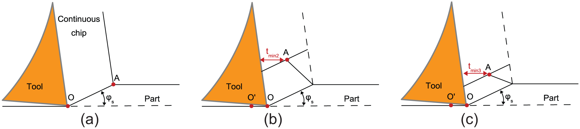
Impact of frequency on minimal thickness of chip: (a) initial state, (b) low-frequency segmentation and (c) high-frequency segmentation.
Concerning the secondary shear zone, it increases with the cutting speed. Indeed, the secondary shear zone thickness rises when the cutting speed grows. The rise in sliding speed due to a higher cutting speed generates a greater gradient velocity. Actually, the variation increases because the speed at the chip interface is equal to zero, unlike the one located at the highest point of the chip. The chip thickness, affected by the velocity gradient, increases with the sliding speed and coincides with the secondary zone thickness. The same observations have been made by Wagner and colleagues4,6 for two different titanium alloys, Ti1023 and Ti5553.
Ti64
The analysis of the Ti64
Chip morphology when
When
Evolution of shear force and chip thickness for Ti64
Chip morphology when
For the upper cutting speed
Chip morphology when
As with the previous structure (Ti64
Feed effect
This section concerns the effect of feed on the chip morphology. As with the previous structure, the analysis was conducted first on the Ti64
Ti64
When the feed exceeds
Chip morphology when
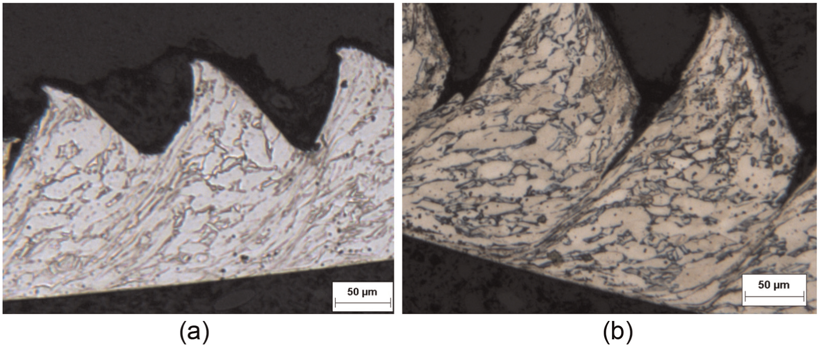
Chip morphology when
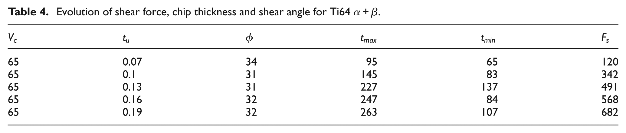
For the upper feed, the frequency and the shear angle are stable. Concerning the shear forces, their values increase with the feed (Table 4). The dissipated energy is higher. This affects the thermal softening and the shear band generation is constant. Moreover, when the feed exceeds
Evolution of shear force, chip thickness and shear angle for Ti64
Ti64
Concerning the
The chip shown in Figure 15(a) explains the complexity of the chip formation which occurs in this material. Indeed, due to the increase in feed, some colonies occur on the chip which are positively oriented for the shearing bands (transversal colonies). There is the significant presence of a hardness phase and of some colonies, which are collinear to the shearing band generation. Consequently, the chip is irregularly segmented with some strong strain concentrations and so some cracks. The chip morphology is also imposed by the nodule size. Moreover, the shearing forces (Table 5) are not sufficient to impose a constant shearing band generation.
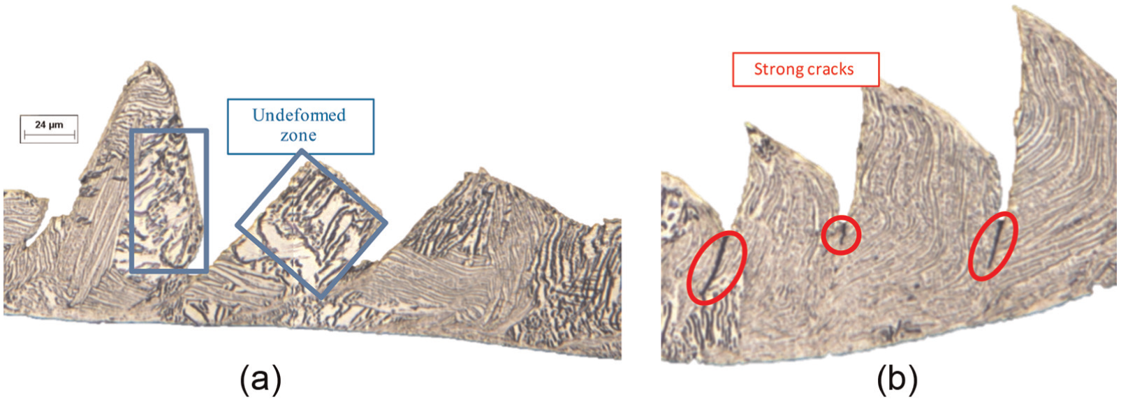
Chip morphology when
Evolution of shear force, chip thickness and shear angle for Ti64
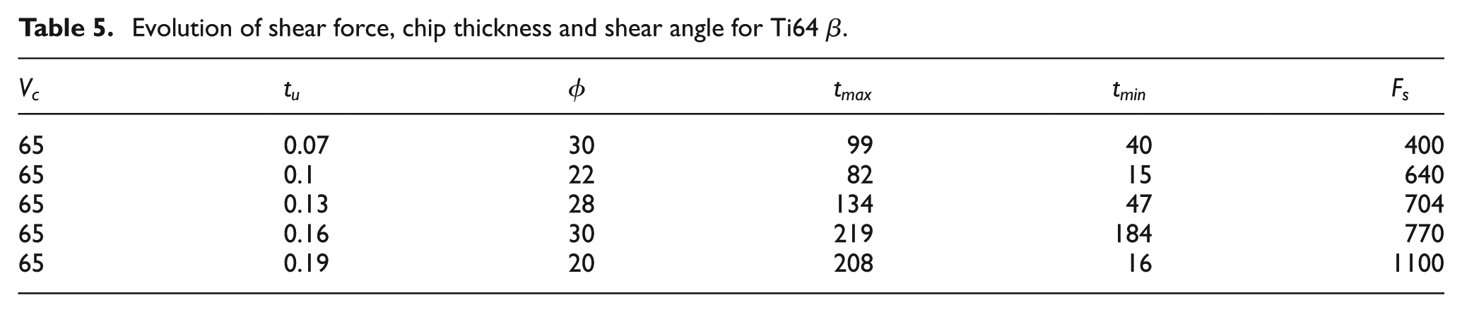
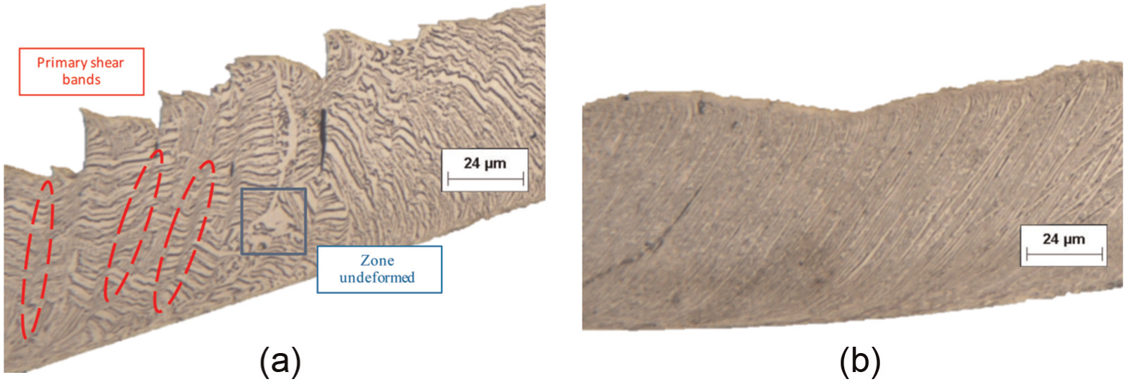
However, the observation of segments mainly comprising transversal colonies shows an increase in crack depth along the shearing bands (Figure 15(b)). When the feed increases to
Chip morphology when
The size of the cracks is still greater. This is due to the increase in shearing forces and the existence of many colonies which are unfavorably oriented to each other in the same thickness. The heterogeneity of some nodules or old
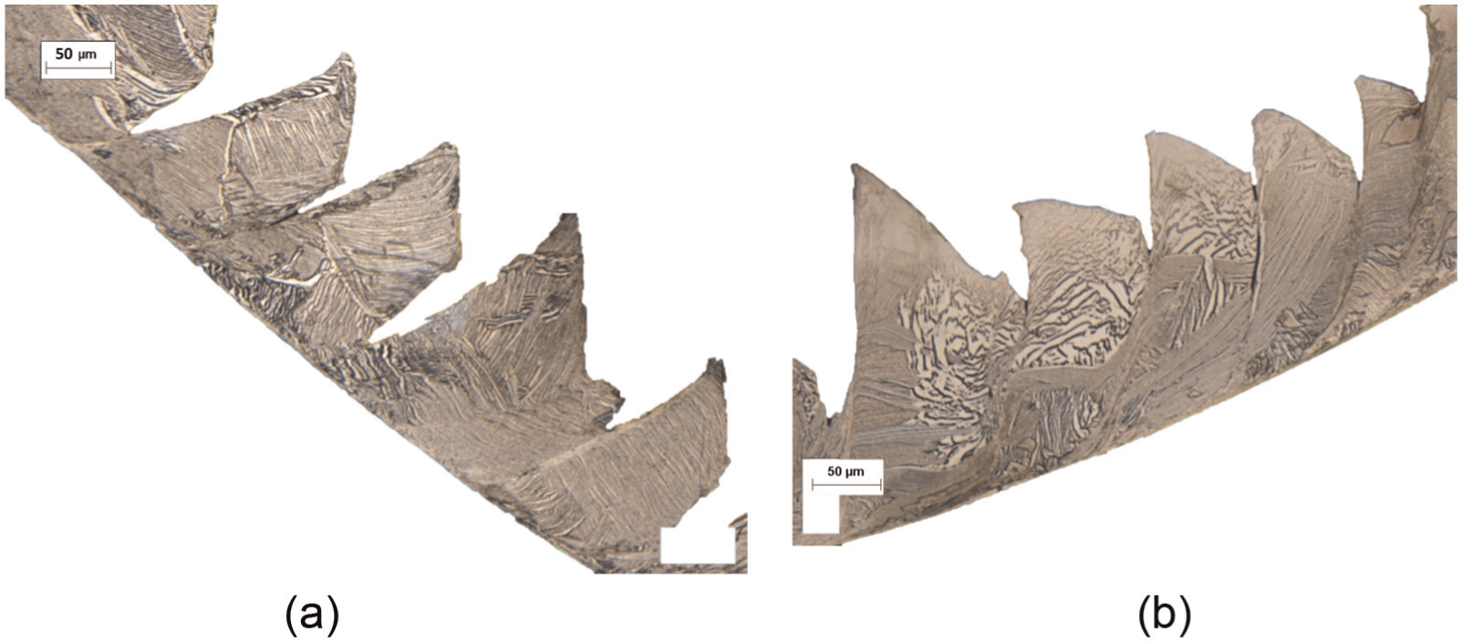
Chip morphology when
Conclusion
The article presents a study of the chip formation of two structures obtained from the same alloy. The study is broken down into two sections.
The first concerns the chip formation of a two-phase structure: the Ti64
The second section describes the analysis of the chip formation of a specific structure obtained from the same alloy. Indeed, contrary to the previous structure, it is not homogeneous. Some zones are observed where the structure is different. This heterogeneity generates a specific chip formation. The study of the chip formation shows that the primary shear band formation is a function of the cutting conditions, but especially a function of the relation between the primary shear band direction and the lamella inclinations. For example, for a single colony, if the primary shear band direction is collinear to the lamellae, a continuous chip is generated, while if the shear band direction is transverse to the colony, a shear band is created and the chip is a saw-tooth chip.
This study shows that the machining of titanium alloy is a function of the microstructure, and this dependency can lead to non-classical phenomena during chip formation. Moreover, this study emphasizes the need to develop new behavior laws which include material heterogeneity to improve machining modeling of these materials. Finally, as mentioned in section “Introduction,” the surface integrity of titanium alloys is very sensitive, thus phenomena observed within the chip can also be generated in the machined surface and need to be studied.
Footnotes
Appendix 1
Declaration of conflicting interests
The author(s) declared no potential conflicts of interest with respect to the research, authorship and/or publication of this article.
Funding
The author(s) received no financial support for the research, authorship and/or publication of this article.