
Abstract
The manufacture of polymer components for biomedical applications is an area that has received much attention from polymer scientists, with high levels of wear resistance achieved, but relatively little research has been done into the machining operations required to manufacture the complex geometries used in total joint replacement. Traditional metal cutting theories have been shown to be insufficient for the analysis of polymer machining, as polymers exhibit viscoelastic behaviour, and unique chip formation mechanisms. This article details an experimental investigation into the effect of tooling and machining parameters on the cutting forces, surface roughness and chip formation in ultra-high-molecular-weight polyethylene, a common material used in biomedical applications. This research quantifies the relative importance of each parameter, the chip formation mechanisms and resulting surface roughness for the given machining parameters and provides new insight into applied research on the machining of polymers.
Introduction
The machining of polymers is an area which has received relatively little interest from the academic community.1,2 While cutting conditions for metals are well understood and well modelled, the viscoelastic behaviour 3 typically seen in polymers complicates analysis and causes some counterintuitive results. Kobayashi and colleagues4,5 were one of the first researchers to perform tests into optimal cutting conditions for a range of polymers.
Viscoelastic behaviour of polymers
In viscoelastic materials, the strain response to an applied load has both instantaneous, or elastic, and transient, or viscous components. The exact nature of the response is a function of the strain history of the material, the temperature of the material and the strain rate at which the load is applied. 6 Typically, higher strain rates and lower temperatures will deliver higher moduli. This behaviour can be easily seen in the form of creep under constant applied stress, or stress relaxation under constant applied strain. There is also significant hysteresis associated with load/unload cycles.7,8
Above the glass transition temperature, the viscous element will dominate the response, while below this temperature the elastic element will dominate. 9 Many polymers have glass transition temperatures below room temperature, so favourable elastic-dominated behaviour can be obtained using low-temperature, or cryogenic, machining, 10 although this often requires careful consideration of contraction rates 11 and a process control system to maintain the appropriate temperature. 12
Chip formation in polymer machining
Achieving favourable chip formation is one of the main challenges in the machining of polymers. 13 The complex rheological behaviour displayed by polymers means that metal cutting theories are not applicable,14,15 and that some of the chip formation mechanisms are unique. 5 The types of chip seen in polymer machining are shown in Table 1. The continuous chip types are those which are of interest, as discontinuous chips provide poor surface roughness and dimensional accuracy. 5 The continuous-flow* type of chip (The asterisk is used to denote that this is a different type of chip formation than the similarly named continuous-flow type, which is encountered in metal cutting. Flow* type chips are never formed in metal cutting.) is produced by high elastic deformation and tends to produce chips of similar thickness to the depth of cut (DOC), while continuous-shear chips tend to be thicker than the DOC, being produced by similar phenomena to that which produces continuous-flow chips in metal cutting. The transition from plastic to elastic yield behaviour complicates analysis and has implications for cutting forces and temperatures. Chip management after machining is also a challenge, as the chips tend to be ductile, and thus will not break easily, instead wrapping around workpieces and tools, and sometimes interfering with the cutting operation.
Types of chip formed in polymer machining.
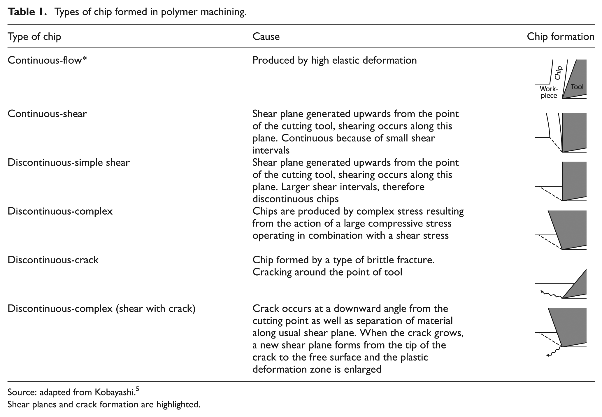
Source: adapted from Kobayashi. 5
Shear planes and crack formation are highlighted.
Ultra-high-molecular-weight polyethylene
In total joint replacement, the use of polymer as a bearing surface in conjunction with metal components is common.16,17 In the case of a hip replacement, the acetabular cup is manufactured from polymer, while in a knee replacement the condyle surfaces of the tibia are replaced by a polymer insert. 18 Polymers also find use in other areas, such as replacement patellas, and in ankle, shoulder and spinal disc replacement surgery. In these applications, the component is subject not only to the standard biomedical rigours of operating in the hostile environment of the human body but also to mechanical loads and the inherent issues of creep, fatigue and wear.
Ultra-high-molecular-weight polyethylene (UHMWPE) is an example of a polymer that has found widespread use in the biomedical industry. The popularity of UHMWPE is a result of the wear characteristics 19 and biocompatibility of the material rather than any inherent machinability or ease of processing.20–22 There is little knowledge in the literature about cutting parameters for use with UHMWPE, as manufacturers of biomedical components tend to closely guard their machining parameters. 22
Research aim
This research is being carried out to provide basic insight into the machining of biocompatible polymers above the glass transition temperature. Fundamentally, this takes the form of analysis of the effects of machining parameters and tool geometry and sharpness on the cutting forces and chip formation mechanism. Also of interest is the effect of changes in the material, either through additives or through cross-linking of the material, on the machinability of the material. The effect of tool sharpness in particular is not well understood with regard to polymer machining.
Experimental materials and method
In order to quantify the phenomena occurring during the machining of polymers, a multisensor measurement chain is required.23,24
Methodology
The experimental methodology shown in Figure 1 was used. It can be seen that this methodology involved an initial phase of material characterisation, subsequent in process measurement of cutting forces and chip formation, and post-process measurement to characterise the machined surface and chip. The pre process measurements were carried out to attempt to measure differences between materials at a molecular level.
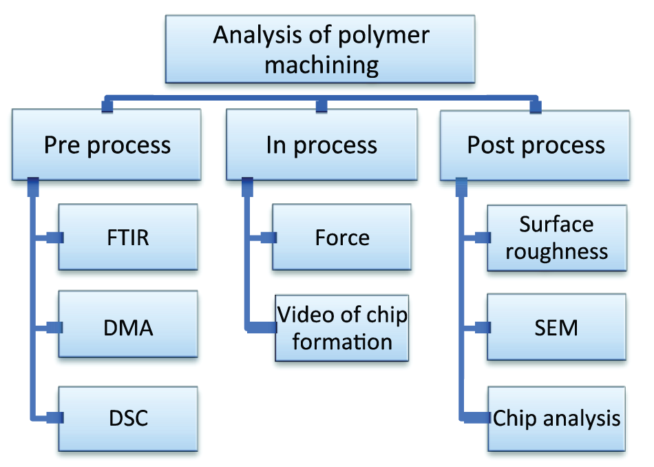
Experimental methodology, showing three phases of quantification.
Materials under study
Three types of UHMWPE were studied:
Plain GUR 1020 (blend of UHMWPE produced by Ticona) (UHMWPE);
GUR 1020 with antioxidant material added (AOX – UHMWPE with antioxidant additives);
Cross-linked GUR 1020 (XLK).
AOX is produced by adding a Food and Drug Administration (FDA)–approved antioxidant material, known as Covernox™, to the base resin before consolidation.25,26 The cross-linking process used in the production of XLK was as follows: 50 kGy gamma irradiation at room temperature, followed by melting at 155 °C for 24 h and annealing at 120 °C for 24 h. Melting and annealing are carried out in a reduced oxygen atmosphere. 22
Typical properties for extruded GUR 1020 are given in Table 2. While it is known that cross-linking improves the wear characteristics of UHMWPE, it can also degrade the mechanical properties, 27 depending on the process used to cross-link the material. In contrast, the addition of typical antioxidants to UHMWPE has been shown to have little to no effect on static mechanical properties, but may act as a plasticiser, 22 which may alter the chip formation mechanism in machining.
Properties of extruded GUR 1020.
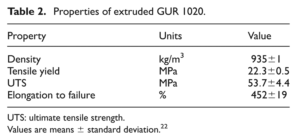
UTS: ultimate tensile strength.
Values are means ± standard deviation. 22
Workpiece design
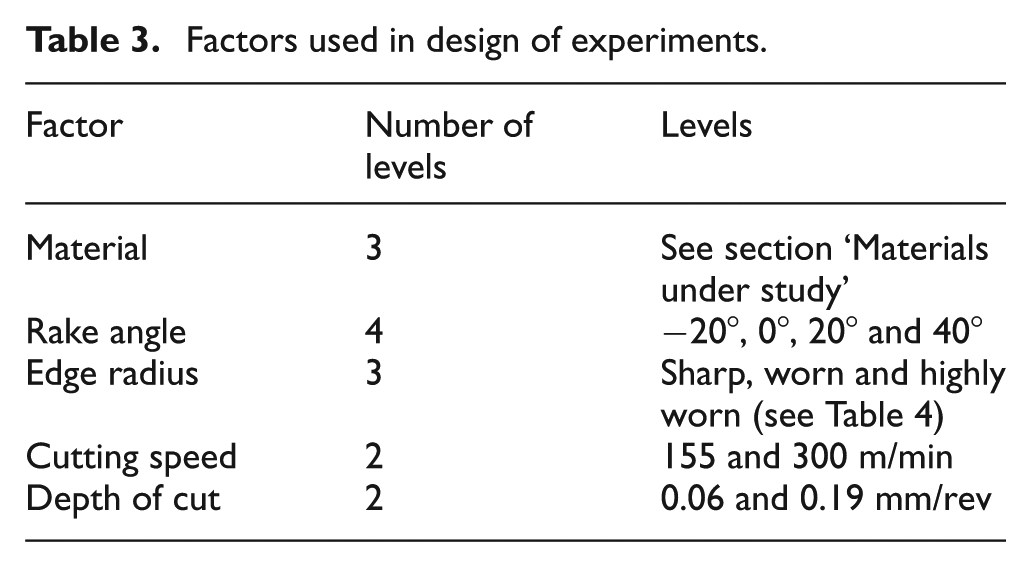
Orthogonal cutting on prepared workpieces was carried out. The workpiece dimensions are shown in Figure 2(a). The cutting operations were carried out using an Okuma LT15-M, using high-speed steel tooling. The constant surface speed feature of the machine was used to provide a constant cutting velocity. The lathe was programmed to carry out machining operations at a range of combinations of cutting speed and DOC, with the DOC being the feed of the tool into the workpiece disc, in millimetre per revolution. The levels used for these parameters are detailed in Tables 3 and 4. It was found that chip build-up leads to issues with corruption of force data. In order to avoid this, a slot was cut in the discs, as shown in Figure 2(b), to prevent a single continuous chip from forming.
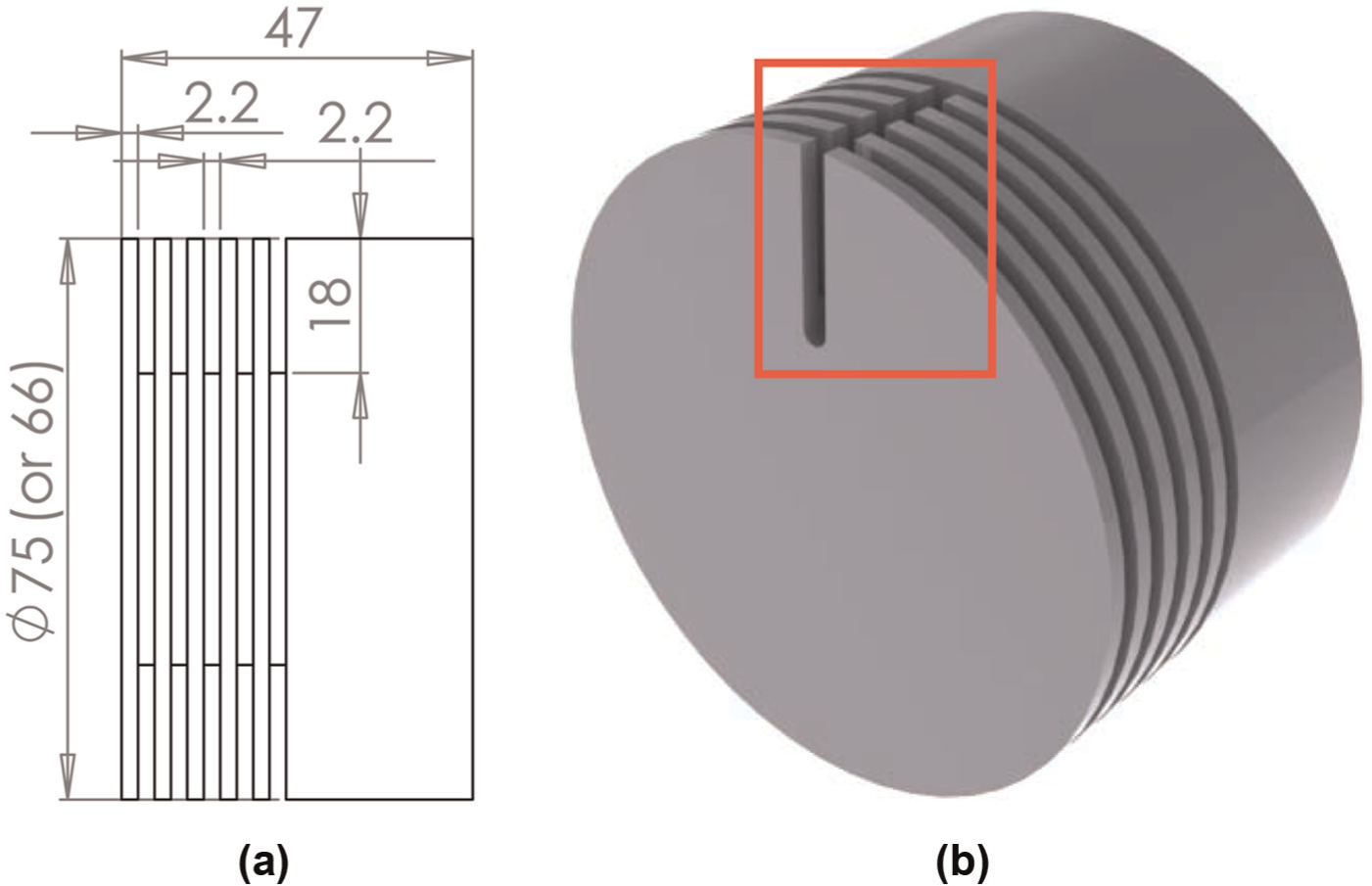
Workpiece design: (a) dimensions (mm) and (b) slot cut in discs.
Factors used in design of experiments.
Sharpness levels.
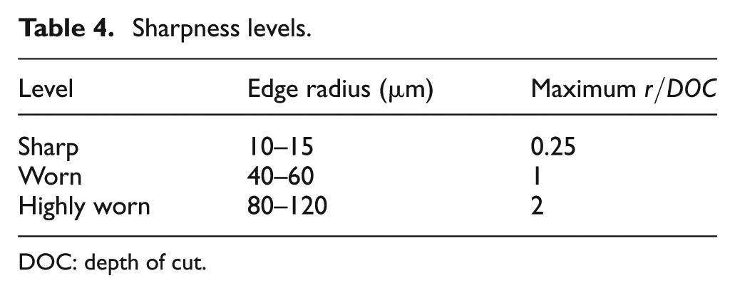
DOC: depth of cut.
Force measurement
Force was measured using a Kistler type 9602 force sensor, mounted as part of a custom tool holder to allow direct force measurement. Calibration was carried out in accordance with ISO 7500-1. 28
Measurement of chip formation
Chip formation was analysed using a high-speed camera (a PixeLINK type 782 with Edmund Optics fixed focal length lens, capable of 180 frames/s) mounted to the tool holder, with the lens parallel to the axis of the spindle. This allowed a side-on view of the cutting operation. A computer rendering of the mount is shown in Figure 3. Chips were also collected from each machining operation, and the cut chip thickness was measured five times for each sample.
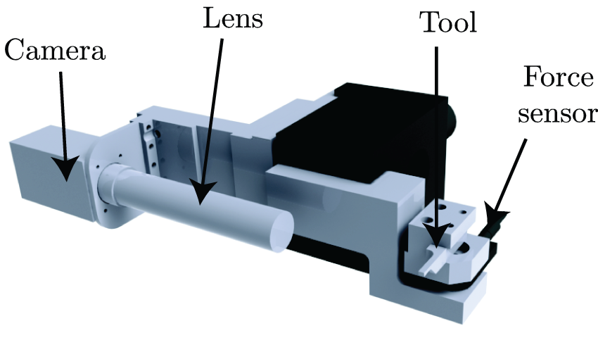
Integration of force and chip formation measurement showing high-speed camera mount.
Surface roughness measurement
Surface roughness measurement was carried out using a Mitutoyo Surftest SJ-400 portable surface roughness tester. Measurements were carried out on five separate locations on each disc to prevent unusual observations from skewing the results.
Data processing
Data acquisition was carried out using a National Instruments CompactDAQ 9178 carrier, using NI LabVIEW SignalExpress software to record the data. Sample force data are shown in Figure 4.
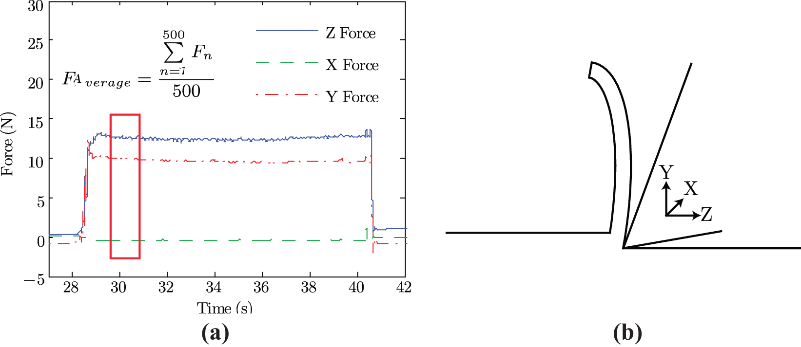
Sample force data and relationship with cutting forces. Cutting parameters were 0° rake angle, sharp tool, 155 m/min of cutting speed, 0.06 mm/rev of depth of cut and material XLK: (a) sample force data and (b) force components.
From these raw data, an average of 500 points of steady-state cutting force was extracted for each axis. An average of 500 points was used as in some conditions, the duration of the machining operation was <1 s, and thus, it was decided to average over the same number of points, with 500 being found to still allow the extraction of steady-state cutting forces for the shorter cuts. The area of interest is highlighted in Figure 4. It can be seen from Figure 4(b) that the Z force corresponds to the cutting force, while the Y force corresponds to the thrust force. In order to compensate for any errors in the mounting of the force sensor, the resultant of the X and Y forces was used as the thrust force. Statistical analysis was performed on these extracted data using Minitab 16.
Analysis of tool–workpiece engagement
The effect of increasing edge radius can be expressed by the ratio of the edge radius of the cutting tool,

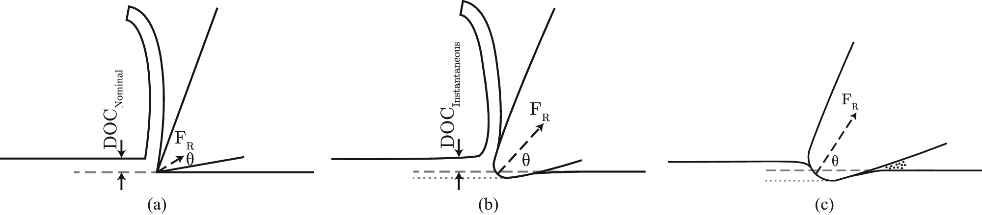
The effect of this parameter on cutting is shown in Figure 5. In the case of a tool with negligible edge radius and a correspondingly small ratio, as shown in Figure 5(a), there will be a single well-defined cutting point, minimal contact on the rake face and close to zero contact on the clearance face of the tool. Increasing the edge radius, as shown in Figure 5(b), increases the contact areas on these two faces, thus increasing friction. This increase in friction will generate more heat and increase cutting forces, and the increased contact area on both faces of the tool will allow a larger heat flux to be transmitted to the tool. This is taken to an extreme level in Figure 5(c), where the edge radius exceeds the DOC, and the material is compressed rather than cut by the tool. In this case, any material removal is likely to be due to compressive cracking of the material, leading to spalling of a layer of material after the tool has passed, and an extremely rough cut surface. There may also be a reduction in heat transmission to the tool due to the lack of a chip in contact with the rake face of the tool.
Cutting arrangement for increasing tool edge radius
In a viscoelastic material such as UHMWPE, it is anticipated that workpiece deformation will occur, 4 even in favourable cutting conditions. If the cutting forces have a large component into the workpiece, then the material will have been compressed and will tend to return to an undeformed state after the tool has passed. As discussed previously, polymers have viscoelastic responses to applied loads, so any expansion of the material after removal of a compressive force will have elastic and viscous components. The elastic component is shown in Figure 5, where it manifests as a difference between the nominal DOC, which is the displacement or penetration of the tool below the original surface of the material, and the instantaneous DOC, which will be less than the nominal value due to the material expanding after unloading. Expansion of the material due to viscous relaxation over time will also alter the effective DOC. Thus, the DOC has three components: the nominal DOC, the instantaneous expansion after unloading and expansion over time due to viscoelastic relaxation.
It is worthy noting that as the ratio of edge radius to DOC increases, the cut surface experiences what is effectively a negative rake angle. When the edge radius approaches or exceeds the DOC, as shown in Figure 5(c), the nominal rake angle of the tool is no longer a factor, as only the rounded edge is in contact with the workpiece.
Design of experiments
In order to identify dominant factors, a full factorial experiment was undertaken. The factors and levels used are shown in Table 3. All tests were performed without the use of coolant, with each test being performed once. The factors were chosen to allow analysis of the effect of material and tool geometry and sharpness, while also reflecting the effect of machining parameters.
The levels for material correspond to the materials under study, while the rake angles were chosen to allow comparison with the study of Kobayashi 5 and to reflect a range of rake angles typically used in industry. The edge radii corresponding to each sharpness are shown in Table 4, along with the maximum values of the ratio between edge radius and DOC for each sharpness level. The sharpness levels were based on the observations from industrial investigations, and DOC levels were then chosen to provide a range of values for the ratio between edge radius and DOC from close to 0 to greater than 1. The cutting speed levels were chosen to provide a large range within the capabilities of the machine used, while allowing comparison with past work.
The following responses were used for statistical analysis:
Cutting force,
Thrust force,
Surface roughness,
Cut chip thickness.
In addition, visual data from the high-speed camera and scanning electron microscope (SEM) were examined on a qualitative basis.
Results and discussion
Analysis of variance methodology
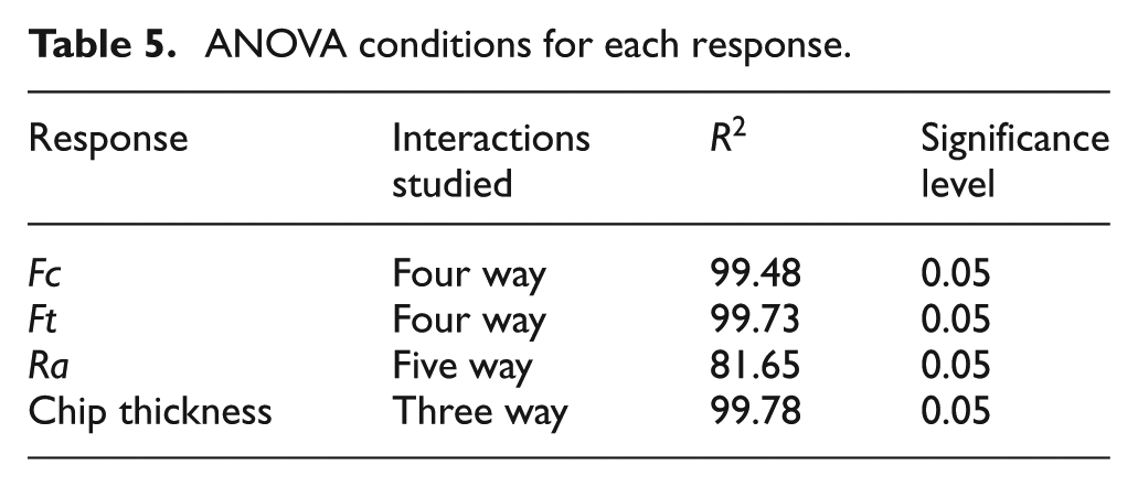
As mentioned in the data processing section, statistical analysis was performed using Minitab 16. This took the form of a general linear model for each response. Details of the analysis of variance (ANOVA) conditions can be found in Table 5.
ANOVA conditions for each response.
Cutting force
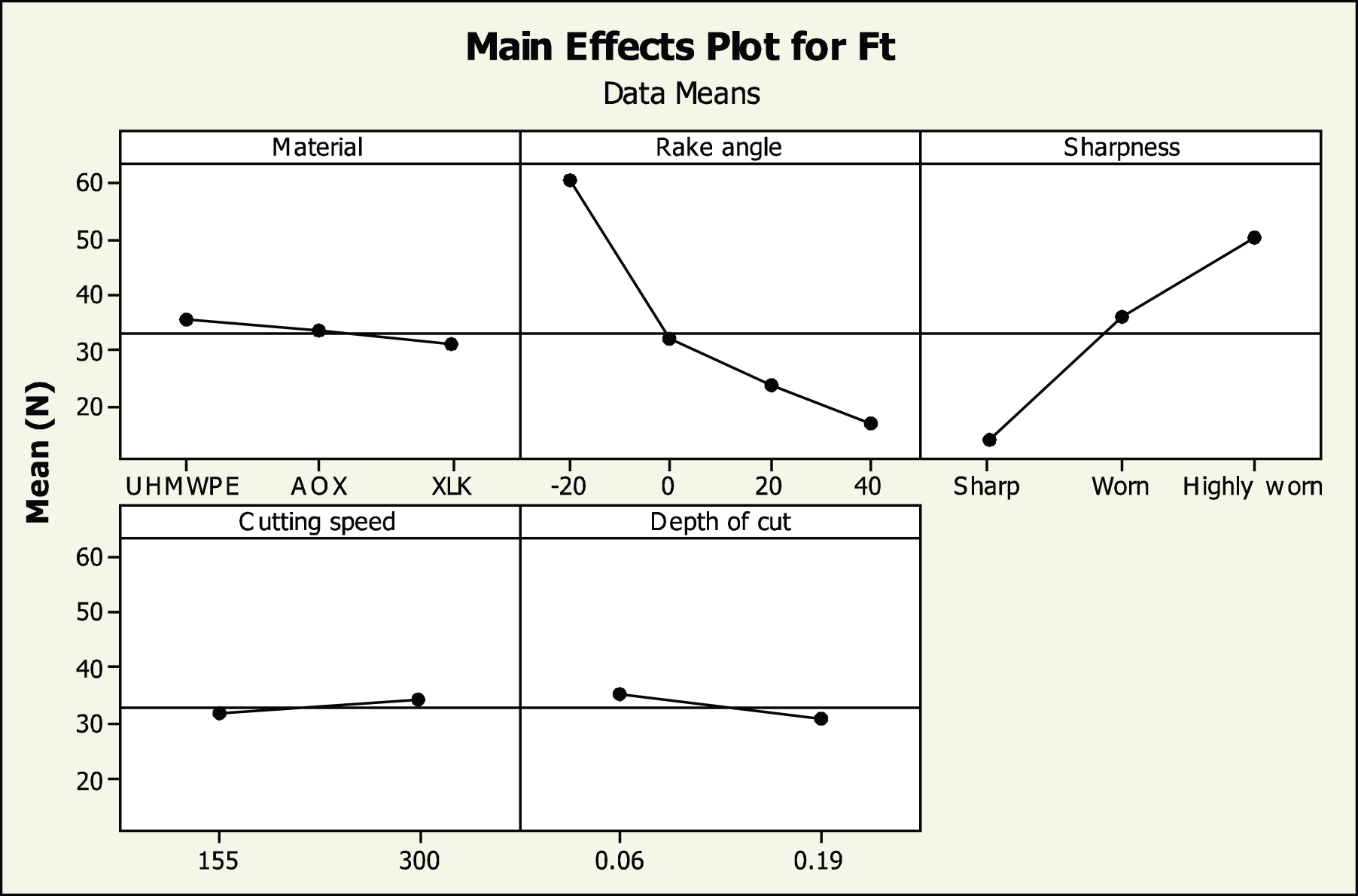
The main effects for cutting force are shown in Figure 6. Cutting force increases with DOC and tool wear, as expected, and decreases with rake angle, indicating easier cutting at higher rake angles. Workpiece material has a small effect, with plain UHMWPE showing higher forces than AOX or XLK. This may indicate that the addition of antioxidant or the cross-linking of the material has an adverse effect on the mechanical properties of the material, with the antioxidant effect due to the additive acting as a plasticiser. It is possible that the relatively small effect of cutting speed is a result of the effects of increased strain rate and softening of material due to frictional heating offsetting each other at the levels used.
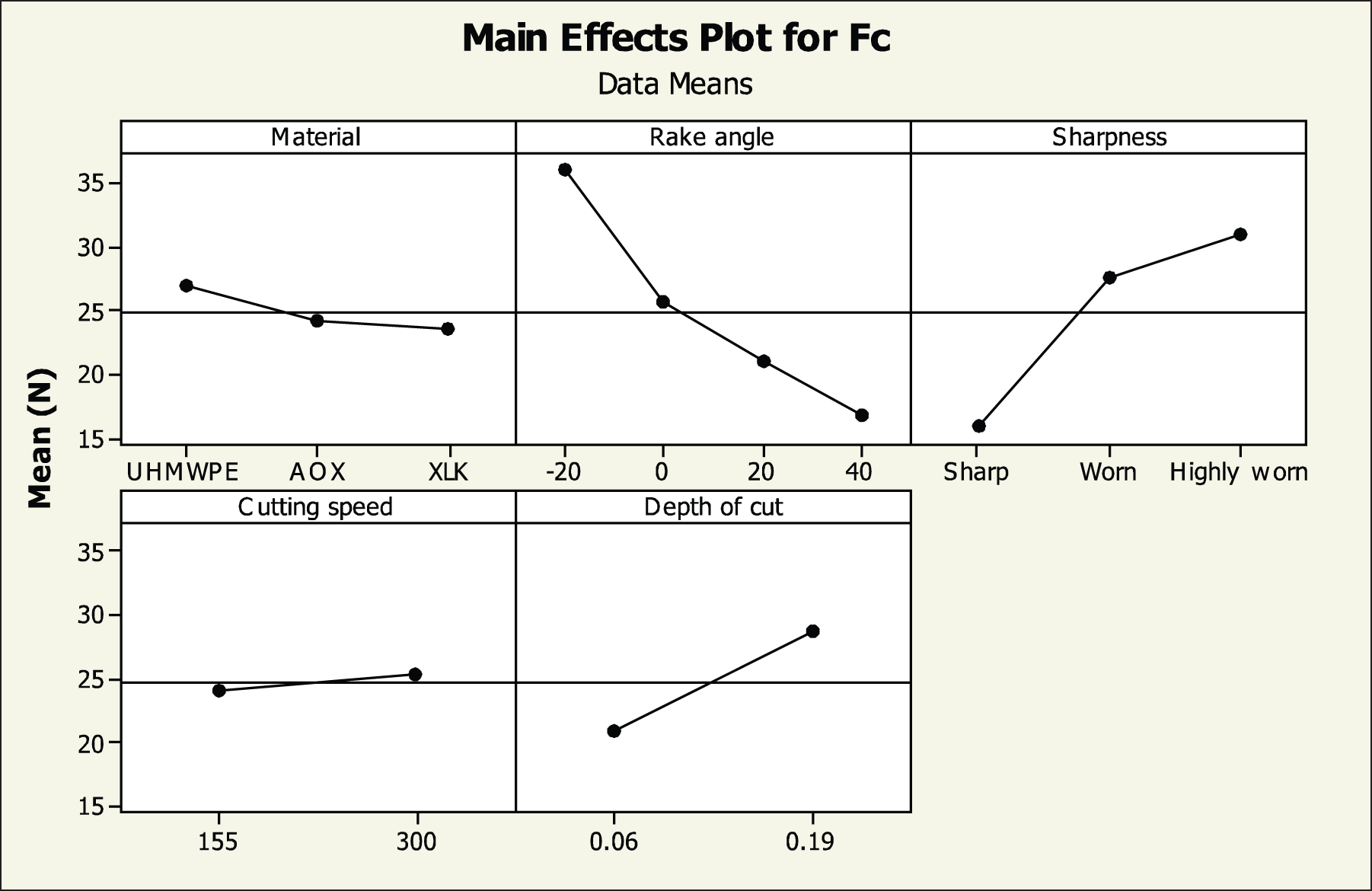
Main effects’ plot for cutting force.
The two-way interactions for cutting force are shown in Figure 7, with a full table of p values from the ANOVA, as shown in Table 6 in Appendix 1. Six of the 10 two-way interactions appear significant, with the material–DOC interaction being marginally significant (
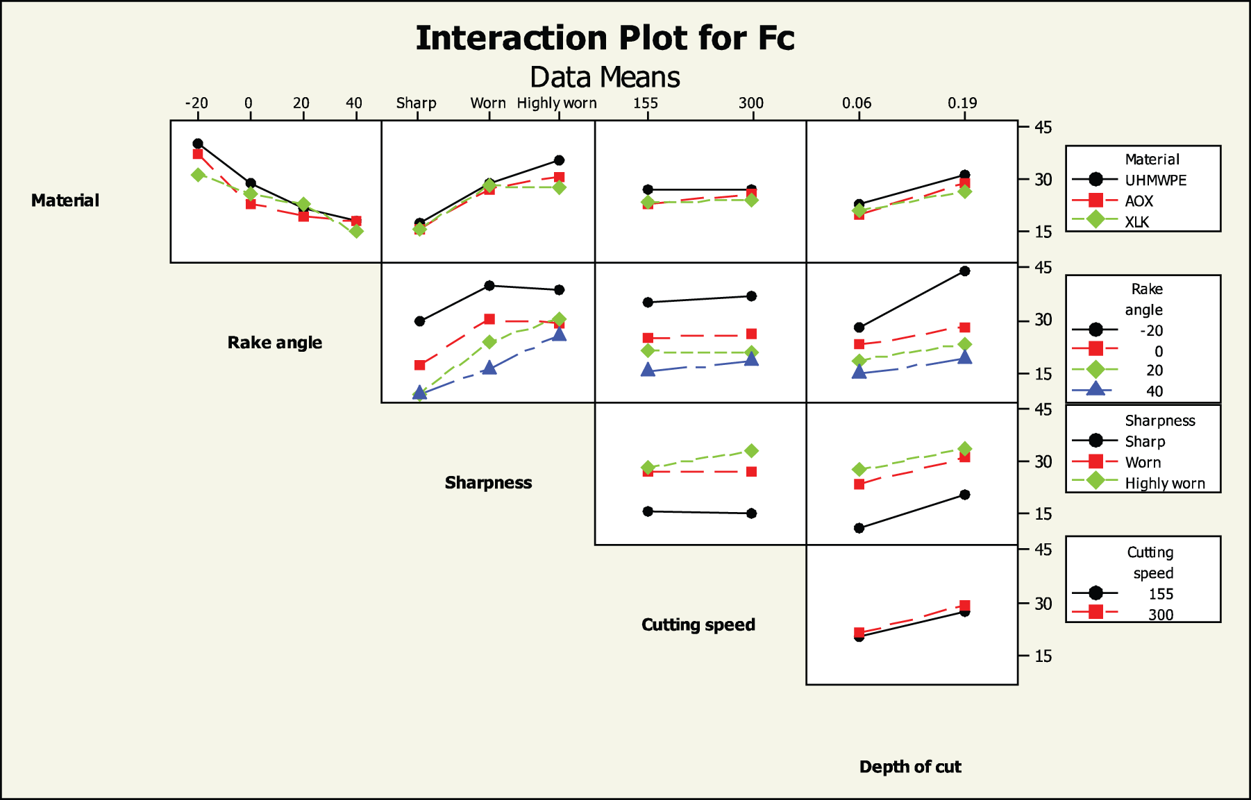
Interaction plot for cutting force.
In addition, the three-way interactions of material–rake angle–sharpness and rake angle–sharpness–DOC were significant, as was the four-way interaction of rake angle–sharpness–cutting speed–DOC. This complex dependency of cutting force on the cutting parameters further indicates that transitions in chip formation mechanism are occurring within the parameter levels studied. Of interest is that cutting speed has the highest p value of the main effects and is significant in only a single two-way interaction and no three-way interactions, but is significant in the four-way interaction. This indicates a relatively weak overall effect from cutting speed compared to the other factors.
Thrust force
The main effects for thrust force are shown in Figure 8. The same overall trends hold as for cutting force, with the exception of DOC, with thrust force decreasing with increasing DOC. This is consistent with the analysis shown in the analysis of tool-workpiece engagement section, as for the large DOC the ratio of edge radius to DOC remained small for all cutting operations.
Main effects’ plot for thrust force.
The two-way interactions for cutting force are shown in Figure 9, with a full table of p values from the ANOVA, as shown in Table 6 in Appendix 1. Seven of the 10 two-way interactions appear significant, with the material–cutting speed interaction being marginally significant (
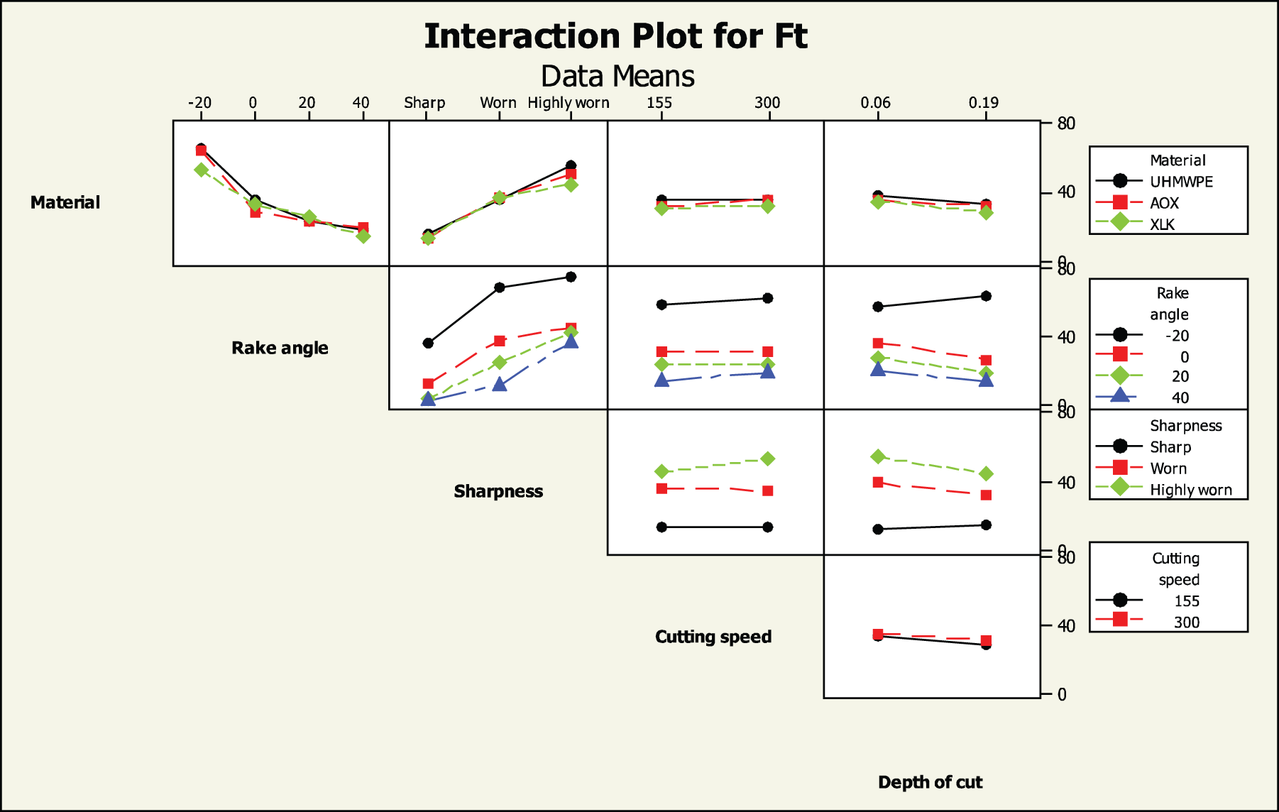
Interaction plot for thrust force.
The three- and four-way interactions for thrust force show the same pattern as for cutting force. The high
Surface roughness
The main effects for surface roughness are shown in Figure 10. Due to the extremely rough nature of the machined surfaces for highly worn tools, as shown in SEM images presented later in this work, it was decided to restrict analysis to sharp and worn tools. It is clear that the change in sharpness from sharp to worn has a large effect on surface roughness. A higher DOC gives a better surface roughness. The main effects’ plot for material shows AOX giving a higher surface roughness result on average compared to UHMWPE and XLK, which could suggest a slight change in chip formation mechanism in AOX compared to UHMWPE and XLK, again possibly due to the additive acting as a plasticiser.
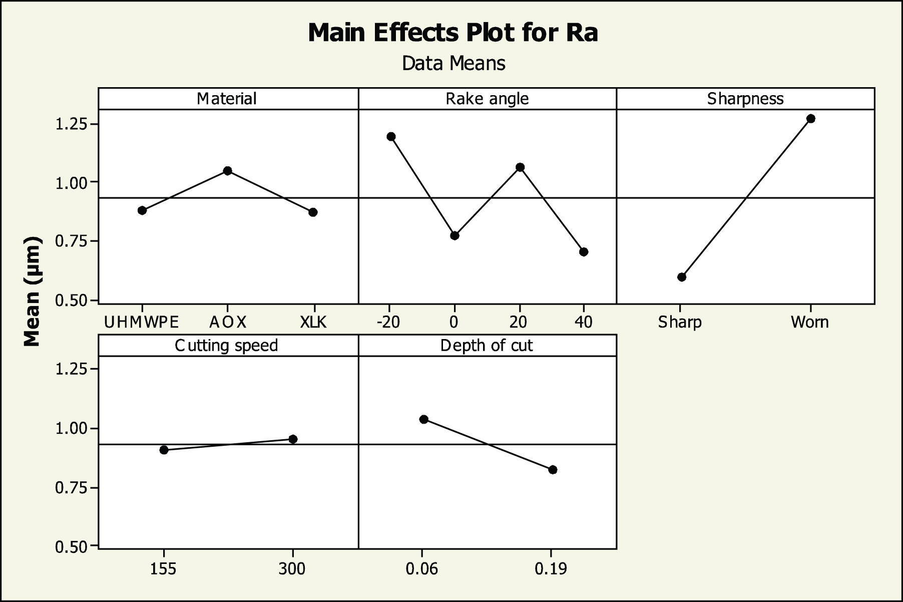
Main effects’ plot for surface roughness.
The two-way interactions for surface roughness are shown in Figure 11. The ANOVA indicates that all of the two-way interactions are significant, with the exception of the cutting speed–DOC interaction. There is an interaction between sharpness and DOC due to the size effect, as the maximum
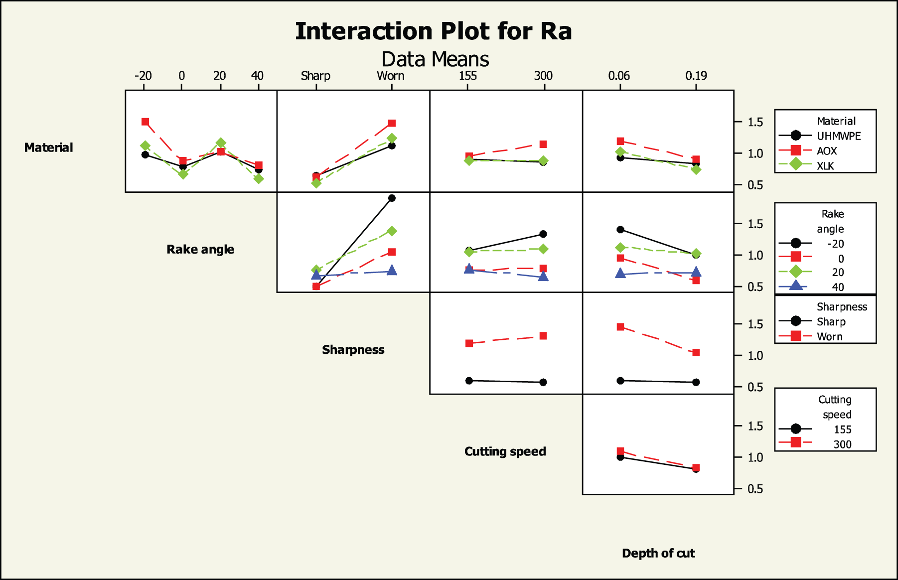
Interaction plot for surface roughness.
The ANOVA also indicates that all but one of the three-way interactions, all the four-way interactions and the five-way interactions are all significant. This coupled with the
Chip thickness
The main effects for the difference between cut and uncut chip thicknesses are shown in Figure 12. Worn and highly worn tools did not produce a continuous chip in all machining conditions, so this analysis was only performed on data from experiments performed with sharp tools. The low correlation between DOC and chip thickness is expected, as the variation due to DOC has been removed. It is clear that the −20° rake angle produces, on average, a chip which is significantly thicker than the uncut chip thickness, indicating that negative rake angle cutting is of the continuous-shear type, as detailed in Table 1. Cutting at neutral and positive rake angles produces a difference close to 0, indicating that the cut is of the continuous-flow* type. The ANOVA indicates that cutting speed is not statistically significant for chip thickness (
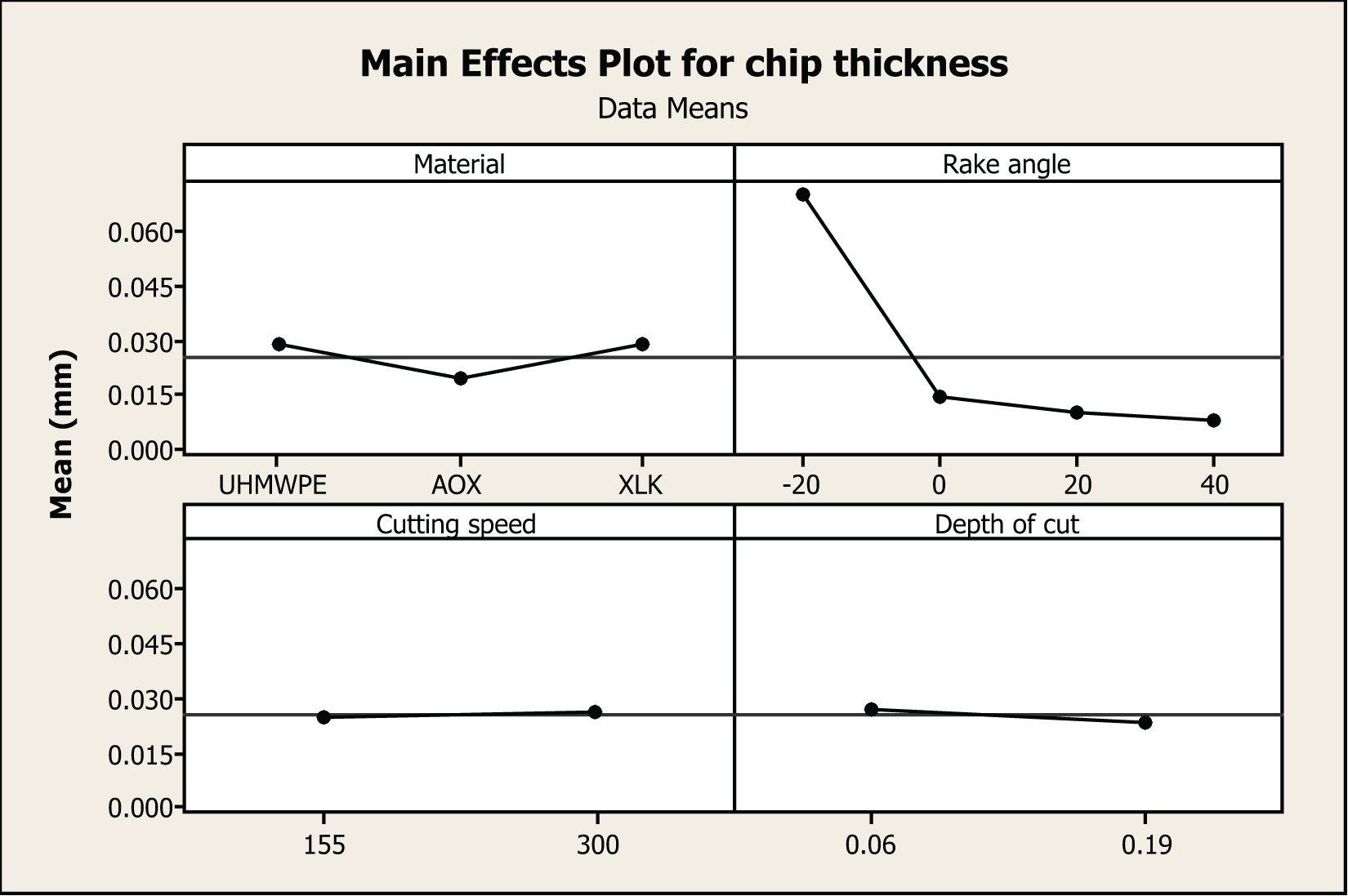
Main effects plot for chip thickness.
The two-way interactions for chip thickness are shown in Figure 13. The interactions involving cutting speed are all statistically insignificant (
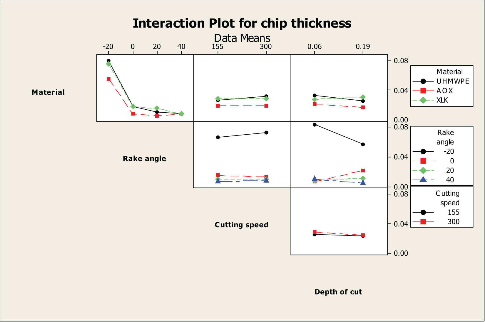
Interaction plot for chip thickness.
Only one three-way interaction is significant for chip thickness, the material–cutting speed–DOC interaction, possibly indicating that the plasticising effect of the additive is sensitive to machining conditions. This is the only level at which cutting speed appears significant for chip thickness, indicating an extremely weak effect overall.
SEM and high-speed video
Varying sharpness
The effect of varying tool sharpness on the surface finish is shown in Figure 14, with high-speed video of chip formation at low depths of cut shown in Figure 15. An example of favourable cutting conditions is shown in Figure 15(a). There is a single cutting edge evident, with no contact on the clearance face and little contact between the chip and the rake face. A smooth continuous chip of the same thickness as the DOC is being formed. The machined surface is shown in Figure 14(a). Based on the chip thickness results, it appears that the continuous-flow* chip formation mechanism is occurring when the sharp tool is used.
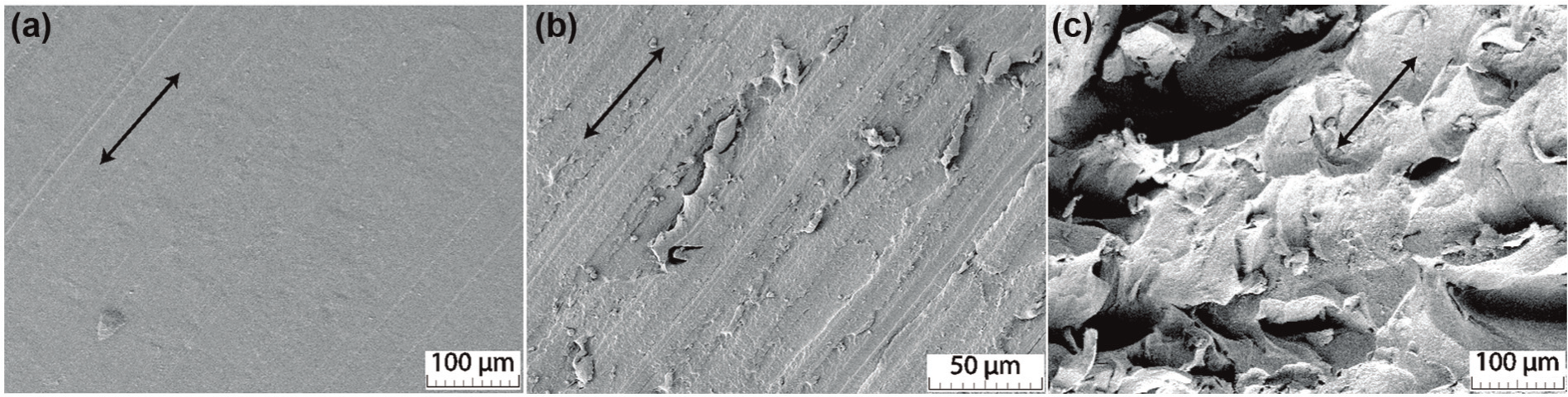
SEM images showing effect of varying tool sharpness. Arrows show direction of cut. Material is XLK, rake angle is
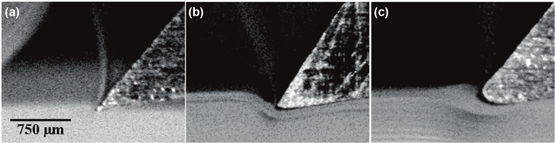
High-speed camera images showing effect of varying tool sharpness at low depth of cut. Workpiece moving left to right relative to tool: (a) sharp tool, (b) worn tool and (c) highly worn tool.
It is clear that while there is a slight degradation in surface quality when the tool is worn, transition to the highly worn state causes a marked decrease in the quality of the machined surface. The chip formation for a worn tool, as shown in Figure 15(b), shows some workpiece deformation around the cutting edge and contact between the workpiece and the clearance face of the tool, but there is still a continuous chip being formed, indicating that the continuous-flow* chip formation mechanism is still occurring.
The surface shown in Figure 14(c) displays an undulating machined surface, unlikely to be of use in any engineering application. The chip formation for this cutting condition is shown in Figure 15(c). There is a discontinuous chip of either the discontinuous-simple shear or the discontinuous-crack type being formed, with very large deformation of the workpiece occurring before the cutting point of the tool, and contact between the workpiece and the clearance face of the tool. This is an example of machining with a tool edge radius exceeding the DOC, as detailed in section shown in Figure 5(c). The expansion of the workpiece after the tool has passed is also evident, as discussed previously.
Varying rake angle
The effect of varying tool rake angle on the surface finish is shown in Figure 16, with high-speed video of chip formation at low depths of cut, as shown in Figure 17. For all four rake angles studied, the SEM images for sharp tools show a surface, which appears free of major defects, and reflect the profile of the tool used in machining. There is nothing to disagree with the surface roughness results for sharp tools presented earlier.
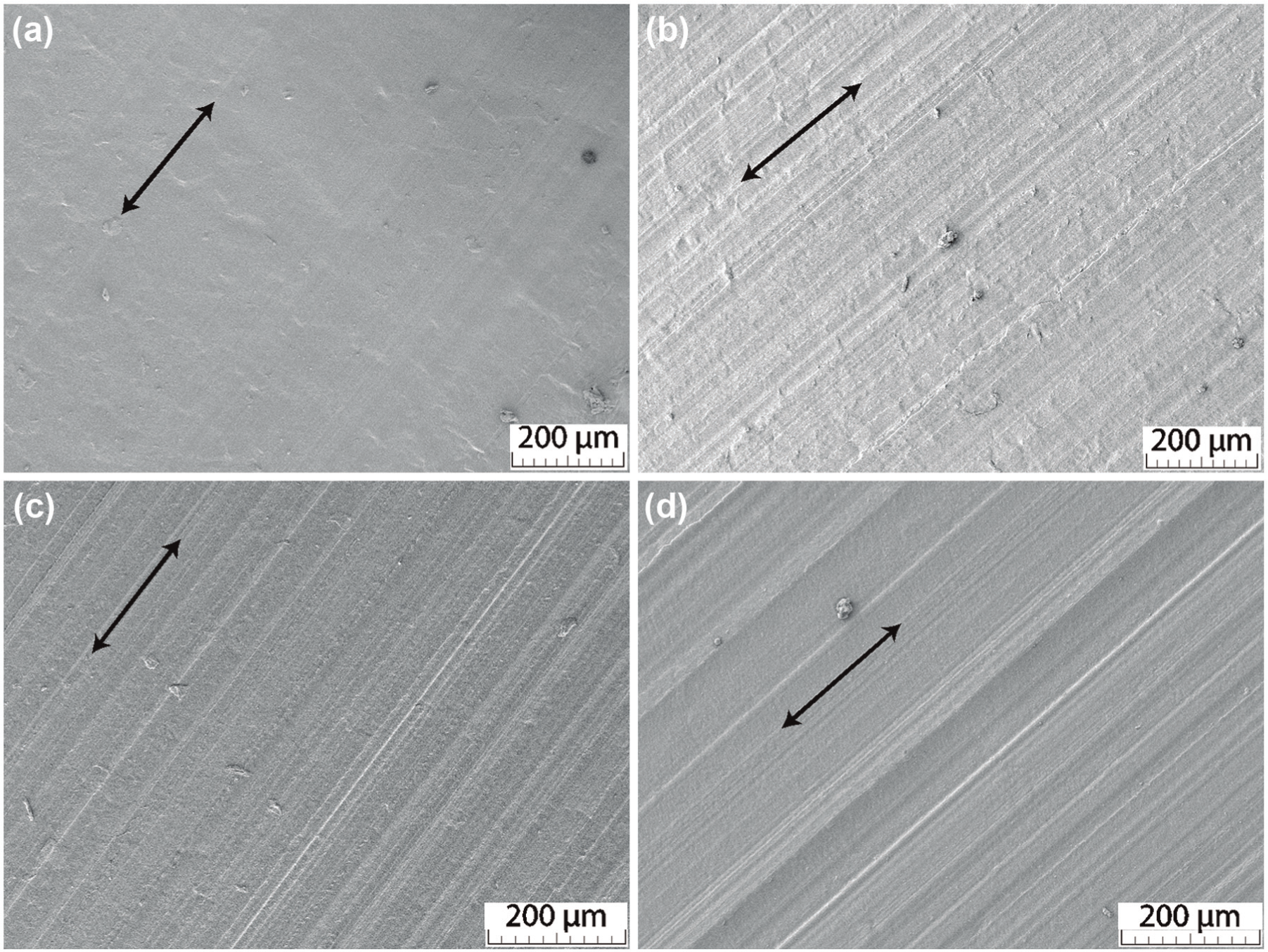
SEM images showing effect of varying tool rake angles for sharp tools. Arrows show direction of cut: (a) −20° rake angle, (b) 0° rake angle, (c) 20° rake angle and (d) 40° rake angle.
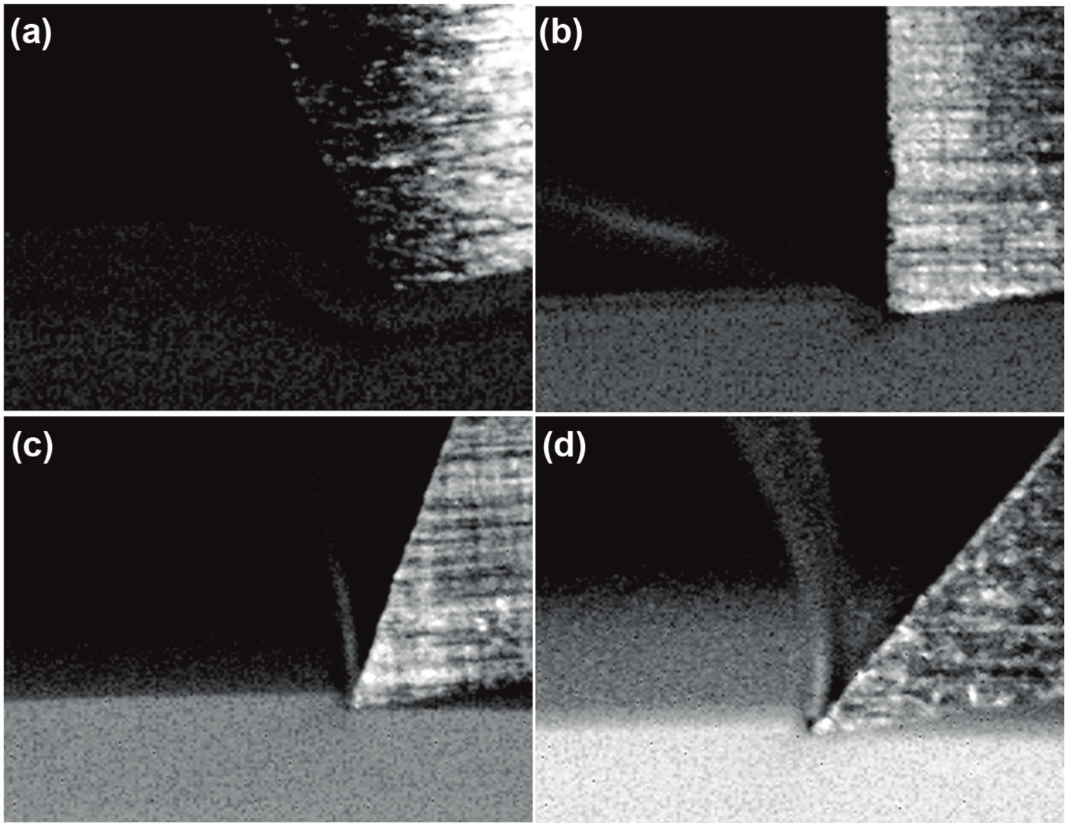
High-speed camera images showing effect of varying tool rake angles at low depth of cut. Workpiece moving left to right relative to tool: (a) −20° rake angle, (b) 0° rake angle, (c) 20° rake angle and (d) 40° rake angle.
High-speed images show continuous chip formation for all rake angles, with some workpiece deformation evident at the negative rake angle, as shown in Figure 17(a). The chip formation mechanism at the negative rake angle appears to be continuous-shear type, while at the neutral and positive rake angles it appears to be continuous-flow* type.
Conclusion
A preliminary investigation into the effect of tool sharpness, rake angle and machining parameters on the machining of UHMWPE was carried out and statistical analysis was performed on the results. From this, the following conclusions can be drawn:
At low depths of cut with worn tools, the area of engagement between the tool and workpiece will present what is effectively a negative rake angle to the workpiece. Negative rake angles deliver higher forces, temperature, surface roughness and chip thickness than neutral or positive rake angles. The chip thickness result for negative rake angle tools indicates that chip formation is of the continuous-shear type, while the continuous-flow* chip formation mechanism is occurring at positive rake angles. This change in chip formation mechanism may account for the increased forces, temperature and surface roughness, as the material is undergoing different yield behaviours.
The models for cutting force, thrust force and chip thickness displayed high
Cutting speed was found to be the least significant factor out of the five responses measured. This leads to a hypothesis that the stiffening effect of a higher strain rate and the softening effect of higher frictional heating may offset each other, within the parameters used. Further investigation is warranted to ascertain the exact effect of cutting speed.
There exists a large two-way interaction between tool rake angle and edge radius for the response of workpiece surface roughness. This can be important for tool life analyses, as a larger rake angle will deliver acceptable surface roughness for longer. Conversely, using a negative rake angle and/or allowing the tool to blunt excessively will lead to extremely poor surface finish.
Workpiece deformation around the cutting edge increases dramatically as edge radius increases. This is reflected in an increase in force on the tool, particularly the thrust force. This indicates that the tool is compressing the workpiece as it cuts, which for a viscoelastic material such as polyethylene may lead to issues with workpiece relaxation, which will cause problems with dimensional accuracy in a manufacturing environment. Further study is required to effectively characterise the effect of compressive cutting forces on polymer relaxation.
Footnotes
Appendix 1
Acknowledgements
The authors would like to thank J.J. Ryan of the Department of Mechanical and Manufacturing Engineering, Trinity College Dublin, for his assistance during testing.
Declaration of conflicting interests
The authors declare that there is no conflict of interest.
Funding
This research project was supported by DePuy Ireland and the Irish Research Council.