
Abstract
To bore elliptical hole, the present research proposes hydraulic servo system and the control method to control the shaft center movement orbit. Considering the control difficulty when there are a small number of collocation points, the present research uses optimal control method to solve the control difficulty. Gauss pseudospectral method, which is often used in aerospace field, is applied to obtain relation between shaft center coordinate and load capacity of bearing. And the relation between load capacity and servo valve spool displacement is deduced with flow continuity equation. After the two steps above, the mathematic relation between shaft center coordinate and spool displacement is eventually obtained. The simulation results indicate that compared to the Eulerian control method, optimal control method has better self-adaptation, faster control rate, and higher control accuracy. Even if the starting movement point of shaft center is not on the expected elliptical orbit, or shaft is disturbed by instantaneous external force or dynamical force, the optimal control method still makes the shaft center orbit quickly get close to the expected ellipse. The present research lays theoretical foundation for new boring method of elliptical hole.
Introduction
As mechanical equipment power and rotation speed increase, the hole in mechanical equipment has to stand increasingly high loading strength. An experiment 1 indicates that ordinary circular hole can generate severe stress concentration in hole’s inner side, which greatly reduces hole’s working lifespan. The fatigue resistance of non-circular piston pin hole is 30% larger than that of circular pin hole, 2 which has numerous advantages in technology and economy. Elliptical hole, such as pin hole of piston,3,4 is one kind of non-circular holes. And there are some kinds of traditional machining methods for elliptical hole, such as mechanical copying method and intelligence boring bar method based on piezoceramics. German KS (a machine company) applied mechanical copying structure to the machining of elliptical hole. 5 The key to precisely machining elliptical hole depends on precise radial feeding mechanism. 6 Kim et al. 7 and Gosiewski et al. 8 presented the machining methods of non-circular holes based on the electromagnetic actuation and conducted the fine boring experiments of elliptical pin hole. Weck and colleagues9,10 and Pasek and colleagues,11,12 respectively, developed their own rapid cutting tool servo mechanisms on the basis of piezoceramics. Moller 13 and Kim et al. 7 applied magnetic bearing to manufacturing process of elliptical hole. This kind of magnetic bearing system can be applied to bore non-circular holes with any shape, but requires a rather complicated structure with high control precision because of the unstable open-loop property of electromagnetic bearing.
Currently, there are those conventional processing approaches (mechanical copying method, intelligence boring bar method based on piezoceramics, etc.) for elliptical hole. But they all, except Moller’s 13 and Kim et al.’s, 7 need aided feeding device fixed on boring bar. Therefore, some disadvantages are inevitable for those traditional approaches, such as complex mechanism, small installation interspace of boring bar, and highly difficult control in precision. Thus, it is necessary to find a new processing approach. The literature 14 brought up a novel and interesting boring approach for elliptical hole and obtained the following conclusion: When movement orbit of shaft center is an ellipse, motion synthesis between the shaft center’s revolution orbit and cutting tool’s rotation orbit is able to form the elliptical tool nose orbit. Elliptical hole’s processing will be realized. So, as long as the orbit of shaft center is an expected ellipse, elliptical hole is able to be processed. In the previous research, literature 15 adopted Eulerian method to control shaft center orbit and made the orbit approach the expected ellipse. Though the control precision of Eulerian method is good, the number of collocation points (i.e. control points) for Eulerian method is up to 300. To complete a lap of the ellipse, the shaft center should move following the 300 collocation points on expected ellipse, which means that the control parameters (i.e. spool displacements of four electro-hydraulic servo valves) should change 300 times per lap. And if the rotation speed of shaft is 50 rps, then the frequency response of electro-hydraulic servo valve will reach up to 15,000 Hz. Such high-frequency response (15,000 Hz) servo valve will make the hydraulic control system’s cost very high, for the price of electro-hydraulic servo valve increases as its frequency response increases. In order to reduce the cost of hydraulic control system, the number of collocation points should be small. Therefore, it is necessary to find a control method which can still maintain high precision under the condition of small number of collocation points, and that is the aim of the present research. It should be noted that the new method should control the shaft center orbit to approach the expected ellipse with less collocation points (i.e. control points). Optimal control method based on Gauss pseudospectral method (GPM) is a method with high precision 16 applied in the present research. Furthermore, the control mechanism of shaft center in the present research may be helpful to the research on rotor vibration abatement.
GPM17,18 is one kind of direct collocation methods, and the method has been widely applied in aerospace field, such as orbital transfer and trajectory design. The reason why that method is widely applied is that GPM has advantages of good accuracy 16 and fast convergence rate 19 in complicated optimal control problems. Huntington et al. 20 worked out the optimal control issue of tetrahedral formation flying with GPM. The results demonstrated the good precision as well as excellent applicability of the GPM for that issue. A new method 21 combining model predictive control and the GPM was successfully applied to nonlinear optimal issue. Huntington and Rao 22 used GPM to work out the issue of determining fuel-optimal trajectories.
GPM is primarily applied to trajectory optimization in spaceflight field, and almost no literature about its application in the control of shaft center movement orbit has been found. In the present research, the expected (or reference) movement orbit of shaft center is an ellipse and very similar to satellite movement orbit. Therefore, the present research attempts to apply the optimal control method based on Gauss pseudospectral theory to the active control of shaft center movement orbit.
Based on the previous work, 14 in order to bore elliptical hole and control shaft center movement orbit to form an ellipse, the present research puts forward hydraulic control scheme and builds mathematic model of bearing-rotor system. And this research adopts GPM to obtain optimal state variables (shaft center coordinates and velocities) and optimal control variable (load capacity of bearing). Electro-hydraulic servo valve is a key to realize the active control of shaft center movement orbit, and the spool displacement of servo valve influences bearing load.23–25 So, it is necessary to establish the relation between the two parameters (spool displacement and bearing load). The above two steps can build the relation between shaft center movement coordinate and spool displacement of electro-hydraulic servo valve. In order to research the advantages of optimal method in controlling the shaft center orbit, the shaft center orbits controlled by the two methods (optimal control method and Eulerian control method) are compared. The compared results indicate that optimal control method has advantages of better self-adaptation, faster control rate, and higher control accuracy. The present research not only discusses the feasibility of realizing new boring method 14 with hydrostatic bearing system but also provides a reference for rotor vibration abatement using the optimal control method.
Analysis
Hydraulic control scheme
In the present research, the shaft center orbit is controlled to form an expected ellipse using a hydraulic system. Figure 1 shows the hydraulic control system of shaft center movement orbit. Compared to previous hydraulic control system with four servo valves in literature,
15
the new system in the present research has only two servo valves. The new scheme not only simplifies the control system but also decreases the cost of the system. Therefore, the new scheme improves the feasibility of machining method.
14
In Figure 1, servo valve
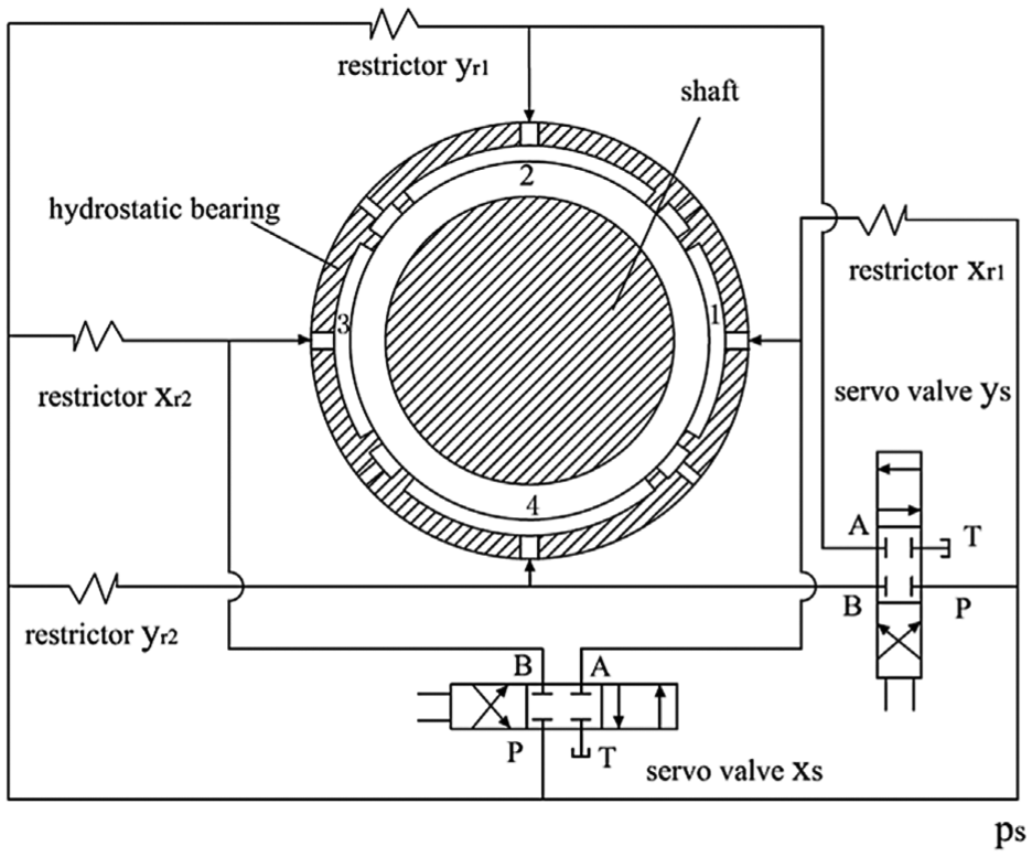
Hydraulic control scheme.
Mathematical model
Figure 2 demonstrates the force analysis of shaft in bearing. In this figure,
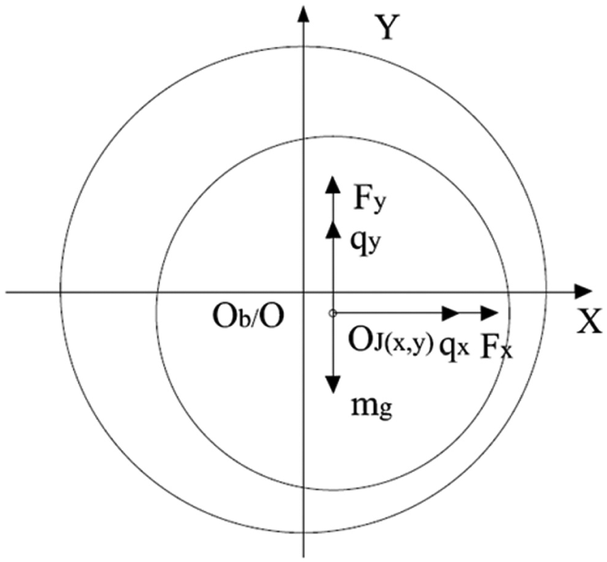
Force analysis of shaft.
The relations between shaft center coordinates

where
Governing dynamic equations of shaft in bearing can be written as
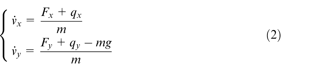
where
If collocation point number is N,
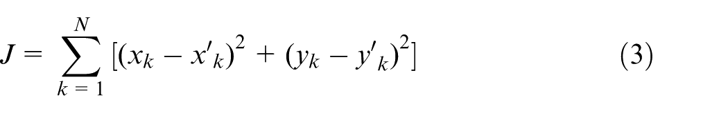
Based on equations (1) and (2), equation (4) can be obtained and given as follows
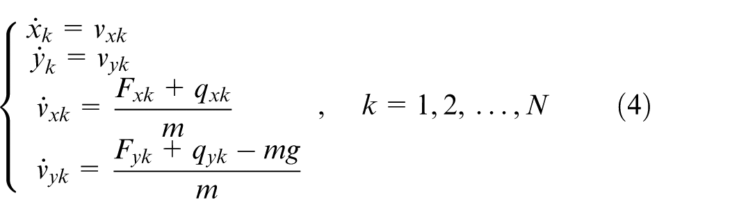
where
Because shaft moves inside the bearing, shaft center coordinates satisfy the following inequations
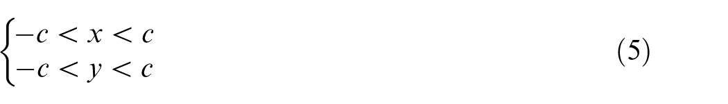
where c is the bearing radial clearance.
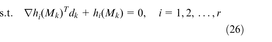
For convenience, the above discussion is summed up as the issue of optimal control


where t is the time,
With the following GPM, the above optimal control issue will be converted into the issue of nonlinear programming (NLP).
GPM
GPM, an excellent optimal control method, is widely applied in spaceflight field. In the present research, when the expected movement orbit of shaft center is an ellipse, GPM will be used to optimize coordinates and velocities of shaft center, and bearing load.
Trajectory optimization problem’s temporal interval is
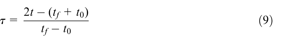
The number of interpolating points of trajectory optimization problem is N + 2, and interpolating points are
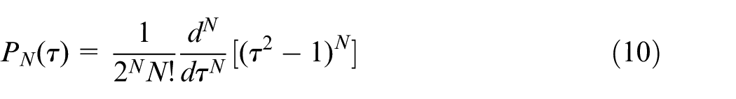
The expression of N order Legendre multinomial can be written as
With L-G points and
where
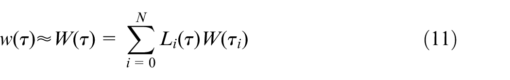
Based on the above method, control variable
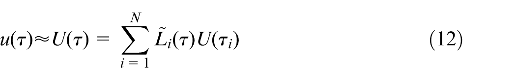
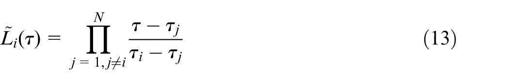
The first-order derivative of equation (11) can be calculated, and the approximate value of
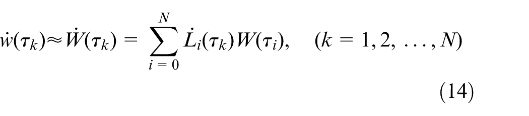
Differential matrix
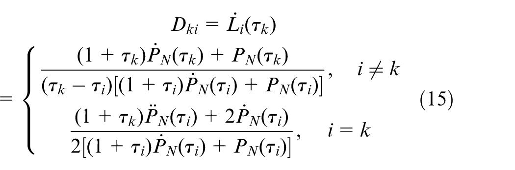
where
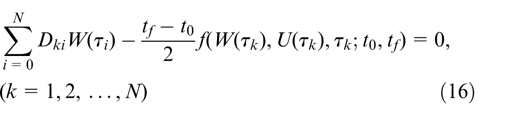
Thus, dynamic constraint (equation (7)) can be rewritten as
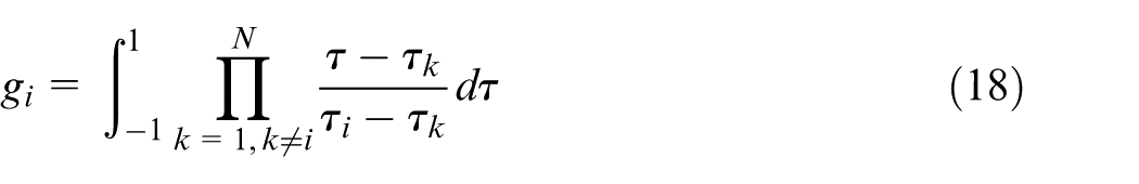
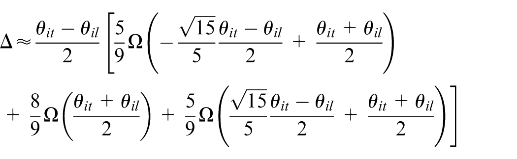
As to a function
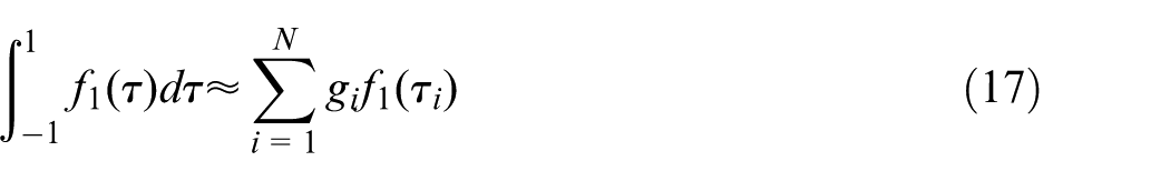
where
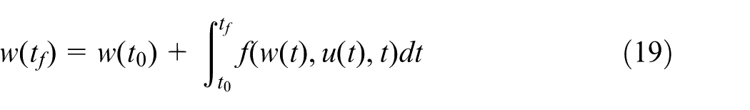
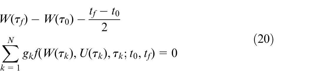
Terminal status satisfies kinetic equation constraint, that is
Combining the equations (17) and (19), one can obtain equation (20) as
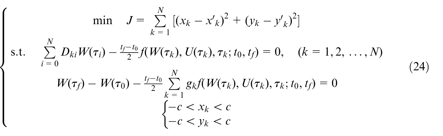
After above conversions, the optimal control problem is changed into NLP problem. The expression of NLP can be given as


where
At present, there are many methods for solving NLP problem, and sequential quadratic programming (SQP) is considered as one of the most effective methods.
SQP method is used to generate a sequence {
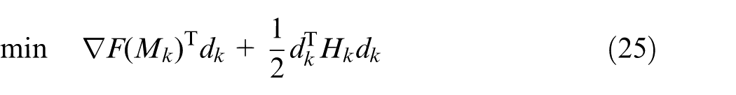
where
where
Step 1. Start with an initial estimate
Step 2. Set k = 0;
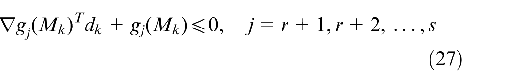
Step 3. Find the solutions of search direction
Step 4. If some convergence criterion such as
Step 5. Update
With the above steps, the optimal parameters of equation (25) can be obtained. When the simulations are carried out, the present research will use SQP method to solve NLP problem by directly using Quadprog function in MATLAB software, getting optimal control parameters.
In this part, GPM can be adopted to establish relations between optimal movement coordinates (
Mathematic relation between load capacity and spool displacement
As seen in Figure 1, hydraulic system can control recess pressure and bearing load by adjusting spool displacement of electro-hydraulic servo valve, so it is necessary to obtain the mathematic relation between load capacity (
When bearing land of hydrostatic bearing is very small,28,29 hydrodynamic effect exerted on the bearing land is very low and can even be neglected. Oil-film force of bearing land is obtained through linearization assignment method, 29 and analytical expression of recess pressure can be solved with flow continuity equation. Moreover, from the literature, 29 the analytic formula for pocket pressure has not only wide application but also high computational accuracy.
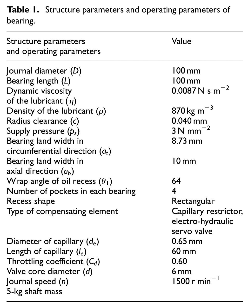
The bearing structure can be seen in Figure 3, and the structure parameters (such as
where
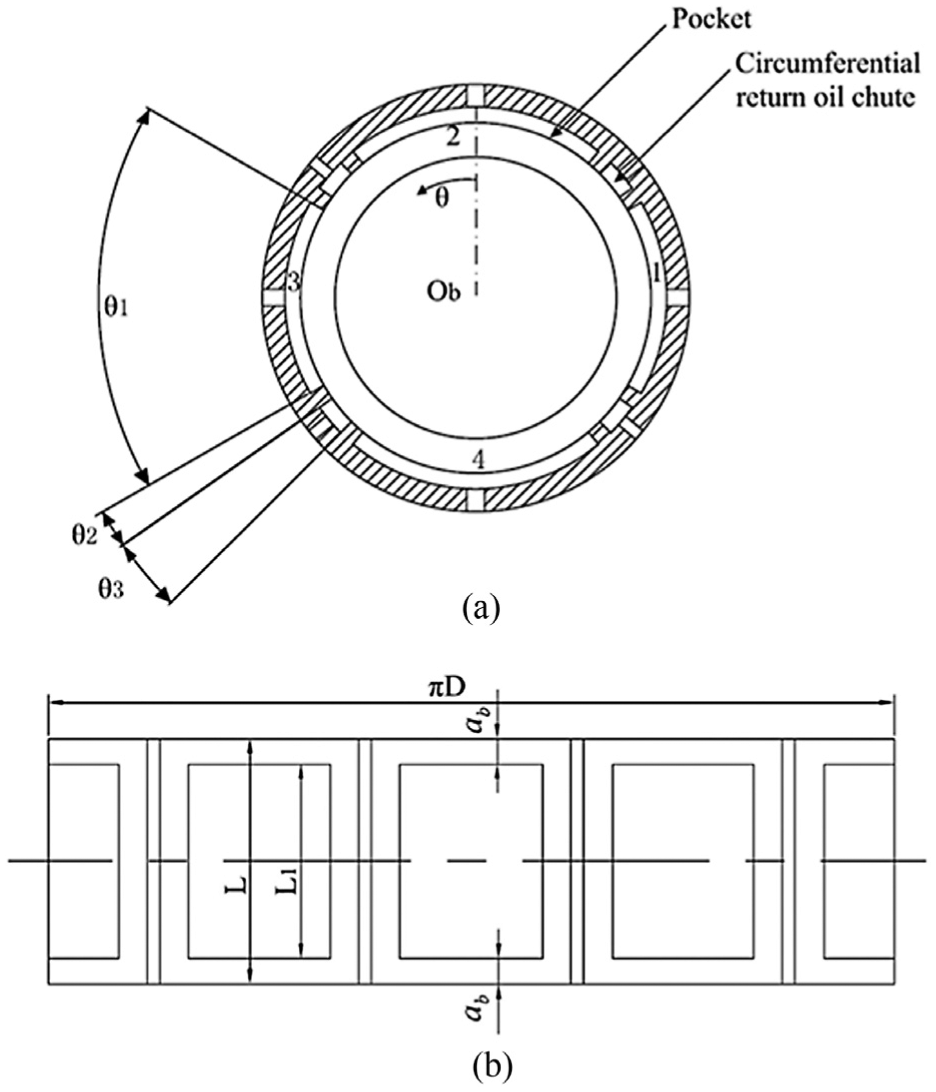
(a) Journal bearing and (b) developed journal bearing.
Structure parameters and operating parameters of bearing.
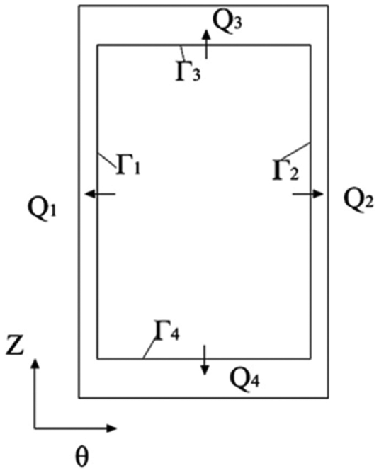
Schematic diagram of boundary flow of bearing pocket.
Variable
where
When valve core position is different, the expression of flow through servo valve is also different, that is
where
The expression of flow through capillary restrictor is given as follows
where
The equation of flow flowing into the ith pocket is

According to the flow continuity equation, the flow into the ith pocket is equal to the flow out of the ith pocket. Therefore, the flow continuity equation can be expressed as

If the values of
Defining

Solving equation (34), one can obtain the recess pressure expression as
When the inequation
According to definitions of variables

Solving the above equation gives
The recess pressure analytical expressions can be obtained by combining equations (35) and (38) as
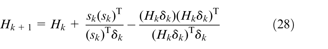
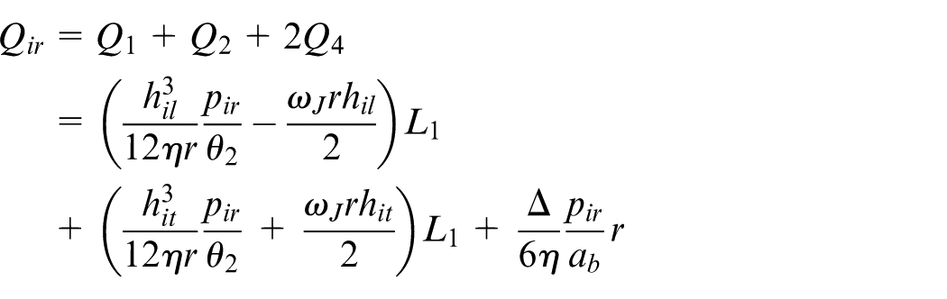
To simplify the calculation, pressure on bearing land will be neglected and only recess pressure will be considered. Therefore, the expressions of load capacity generated by the ith pocket are
where
The expressions of load capacity generated by four pockets are 15
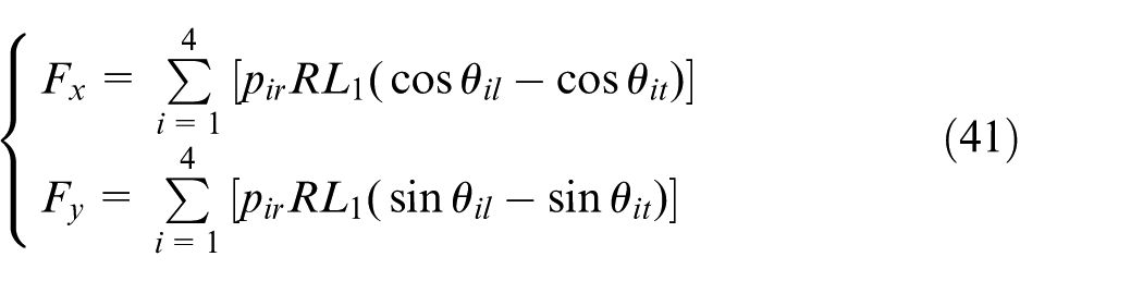
Thus, combining equations (39) and (41) can establish the relationship between spool displacement (
Results
The whole computational process is as follows: first, GPM is used to get optimal coordinates of shaft center and optimal load capacity, and then equations (39) and (41) are adopted to gain relation between load capacity and spool displacement. After the two steps, mathematic relation between the spool displacement and the optimal coordinates of shaft center will be obtained.
In the following part, an example is used to show the feasibility and controlling effects of optimal control method in the control of shaft center orbit.
Here, suppose elliptic equations of expected movement orbit of shaft center to be
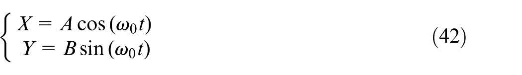
where
In order to implement the control of shaft center movement orbit, a certain number of control points (i.e. collocation points) on expected ellipse orbit of shaft center need be selected. The present research selects only 10 collocation points (i.e. N = 10). According to equation (10), Legendre multinomial equation of 10 collocation points is
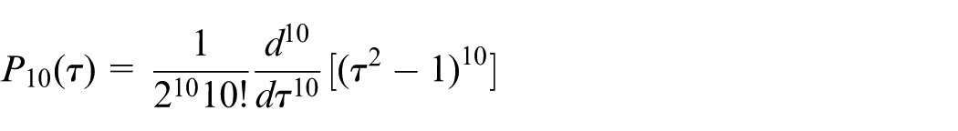
In total, 10 null points of Legendre multinomial equation can be obtained by solving the equation
In equation (42), variables A and B are set as 0.5 and 0.25, respectively. The shaft rotation speed is 1500 r min−1, and the rotational speed
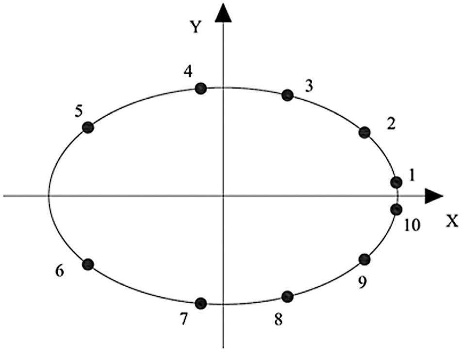
Ten collocation points on elliptical shaft center orbit.
In the present research, the ultimate object of optimal control is to make the optimal coordinates of shaft center approach the expected points’ coordinates (i.e. the collocation points in Figure 5). Table 1 indicates the structure and operating parameters of hydrostatic bearing system in Figure 3. Combining equations (24), (39), and (41) can establish the relations between shaft center’s optimal movement coordinates (
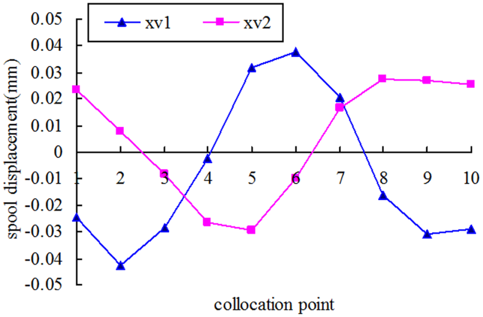
Variations of spool displacements of servo valves.
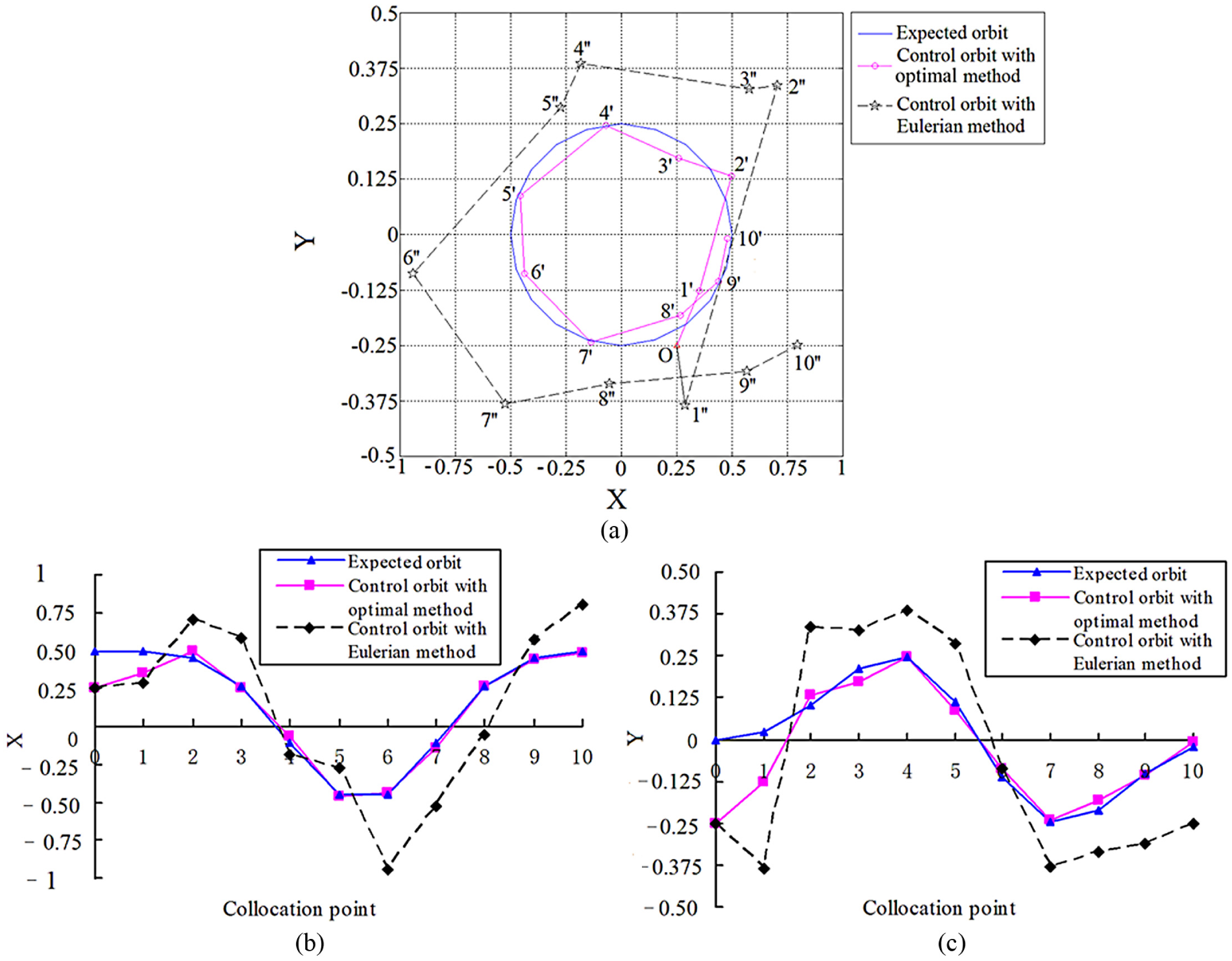
The present research first studies the control simulation of shaft center movement orbit (seen in Figure 7) when there is no external force, that is, the equations
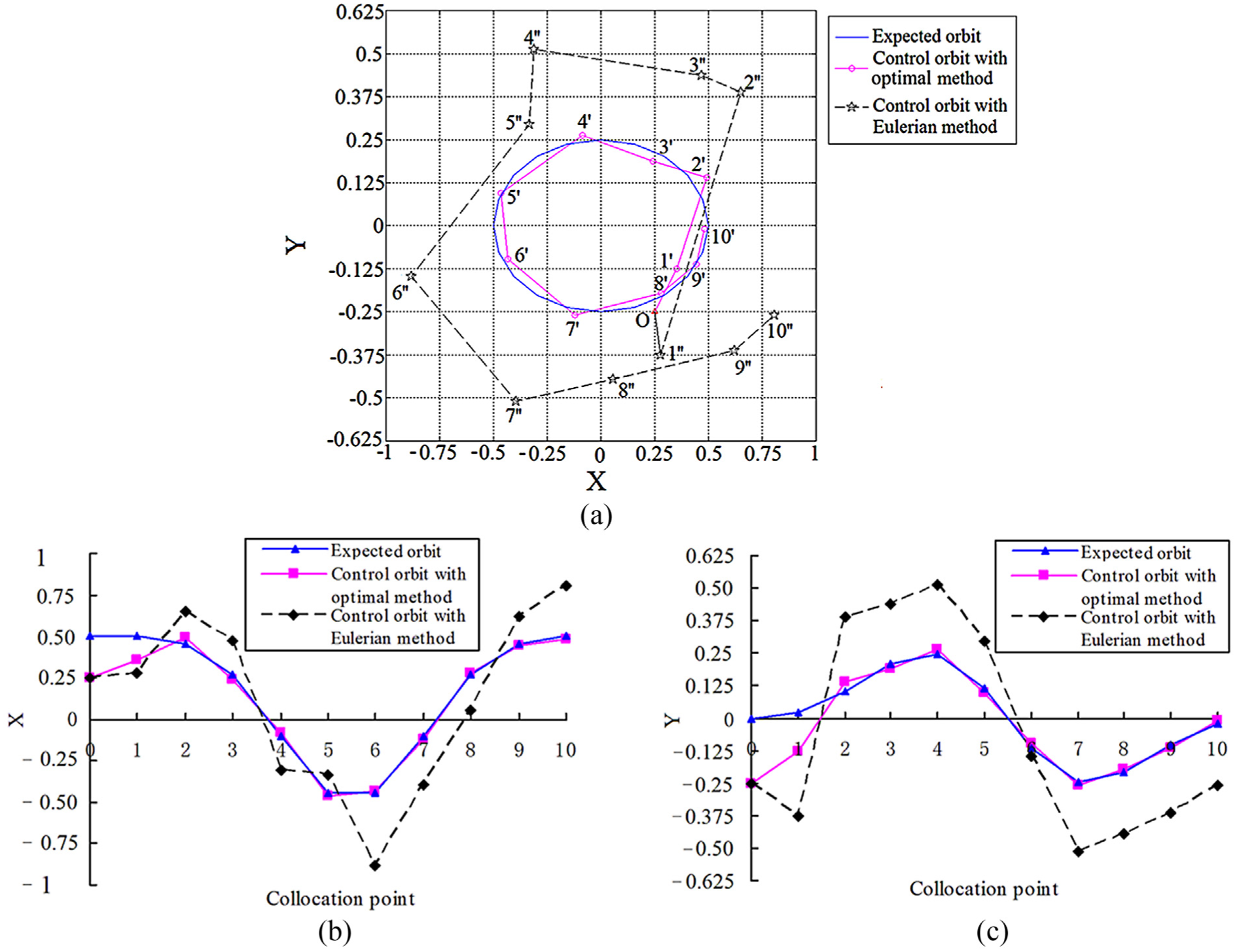
(a) Control simulations of shaft center movement orbit (
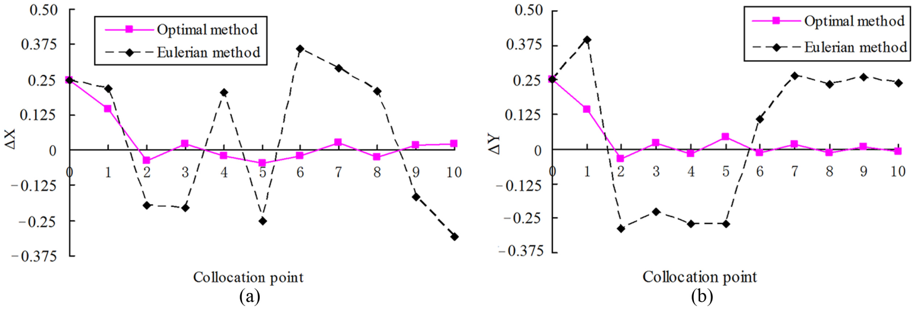
Figure 8 shows the tracking errors of shaft center coordinates in X-direction (seen in Figure 7(b)) and Y-direction (seen in Figure 7(c)). It can be seen that the optimal control method has much smaller tracking errors than Eulerian control method. When utilizing the optimal method, the tracking error curve of shaft center orbit can be divided into short adjustment stage (from collocation point 1 to point 2) and long steady stage (point 2 to point 10). There are small tracking errors in the steady stage. For example, in the steady stage, the biggest absolute error of shaft center coordinate in X-direction is 0.0233, and the biggest relative error is 4.66%; the biggest absolute error of shaft center coordinate in Y-direction is 0.0219, and the biggest relative error is 4.38%. But with Eulerian method, the tracking errors of shaft center coordinate are very large. For instance, the biggest relative errors of shaft center coordinate in X-direction and Y-direction are 87.11% and 54.35%, respectively. From Figures 7 and 8, though the starting movement point of shaft center is not on the expected ellipse, the optimal control method still makes the coordinates of shaft center get close to the expected ellipse orbit quickly.
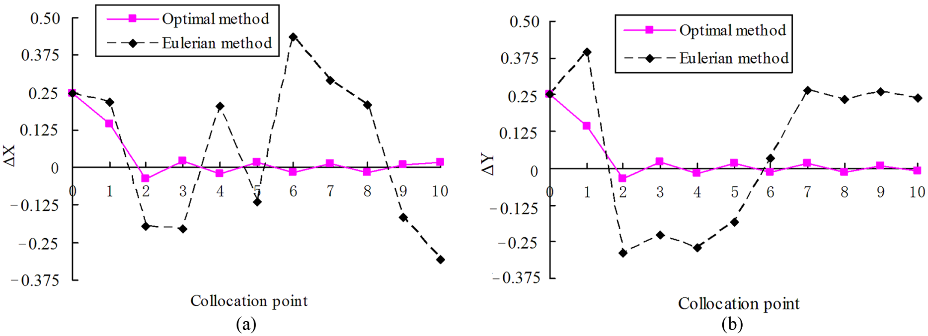
(a) Tracking errors of shaft center coordinates in X-direction (
When shaft rotates in a bearing, shaft center movement orbit may be disturbed by instantaneous external force. Figure 9 shows the shaft center movement orbit with the two control methods when the shaft is disturbed by instantaneous external force. In Figure 9, the instantaneous external force
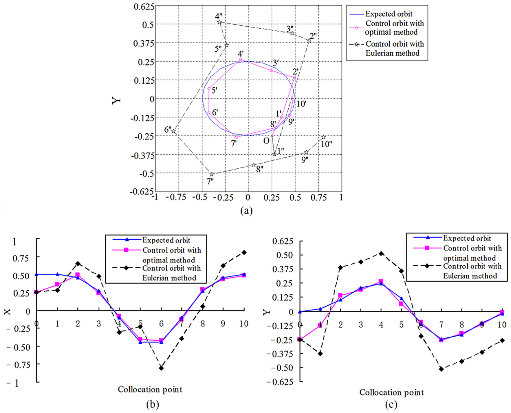
(a) Control simulations of shaft center movement orbit (
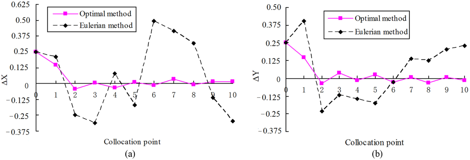
Figure 10 presents the tracking errors of Figure 9(b) and (c). As can be seen from Figure 10, with the optimal control method, the tracking errors of coordinates when shaft center moves on point 5 are the biggest in the steady stage (point 2 to point 10), and the biggest relative errors of shaft center coordinate in X-direction and Y-direction are 9.05% and 8.36%, respectively. But when shaft center moves on other points (from point 2 to point 10, excluding point 5), the relative tracking errors of coordinates are smaller than 5.82%. With the comparison of Figures 10 and 8, when Eulerian method is used, the tracking errors of shaft center coordinates on point 5 become bigger because of instantaneous external force, and the relative tracking errors of shaft center coordinates in X-direction and Y-direction are 52.24% and 55.22%, respectively, in Figure 10. From Figures 9 and 10, when the shaft is disturbed by instantaneous external force the shaft center orbit is also disturbed, but optimal method can make the shaft center orbit quickly approach the expected ellipse again. The instantaneous external force does not have big effects on the shaft center orbit with the optimal control method.
(a) Tracking errors of shaft center coordinates in X-direction (
When shaft rotates in a bearing, the shaft may be also disturbed by dynamical force whose value and direction change with time. Therefore, the present research operates control simulation of shaft center orbit under the dynamical force. In Figure 11, the dynamical force conditions are
(a) Control simulations of shaft center movement orbit (
Figure 12 shows the tracking errors of Figure 11(b) and (c). It can be seen that the tracking errors of shaft center orbit with optimal method become a little larger by comparing Figures 8 and 12. For example, the biggest relative errors of shaft center orbit (pink line segment) in the X-direction and Y-direction are 7.31% and 7.19%, respectively, in Figure 12. Because of the effects of dynamical force, the tracking errors of shaft center orbit with Eulerian method also become bigger. For instance, the biggest relative error of shaft center orbit coordinate in X-direction reaches up to 98.52%. From Figures 11 and 12, when the shaft is disturbed by dynamical force and the optimal control method is used, the relative tracking errors of shaft center orbits can keep within 7.31% in the steady stage. And the dynamical force does not have large effects on the control precision of optimal control method.
(a) Tracking errors of shaft center coordinates in X-direction (
Conclusion
Based on preliminary work,14,15,28,29 the present research researches the hydraulic control scheme to bore elliptical hole and uses optimal control method based on GPM to realize control simulation of shaft center movement orbit. The present research not only discusses the feasibility of realizing new boring method 14 with hydrostatic bearing system but also provides a reference for rotor vibration abatement with the optimal control mechanism of shaft center. The conclusions are as follows:
Based on similarity between the movement orbit of shaft center and the satellite movement orbit, the present research applies the optimal control approach based on GPM in aerospace field to shaft center orbit control. Compared to Eulerian control method, 15 optimal control method can control the shaft center orbit with very few collocation points, which can decrease the frequency response requirements of electro-hydraulic servo valve and system cost. And the comparison results also show better feasibility and more advantages of optimal control method in the application of the new machining method. 14
Compared to Eulerian control method, optimal control method has higher control accuracy. When the shaft is disturbed by instantaneous external force, the biggest relative errors of shaft center orbit in the steady stage (point 2 to point 10) in X-direction and Y-direction are 9.05% and 8.36%, respectively, with the optimal control method. But the biggest relative errors of shaft center orbit with Eulerian method in X-direction and Y-direction are 52.24% and 55.22%, respectively. When the shaft is disturbed by dynamical force and the optimal control method is used, the relative tracking errors of shaft center orbit can keep within 7.31% at most of points. But the tracking errors of shaft center orbit with Eulerian method is very big, and the biggest relative error of shaft center coordinates in X-direction reaches up to 98.52%.
Compared to Eulerian control method, optimal control method has faster control rate. The simulation results prove that when shaft center’s starting movement point is not on the expected ellipse, optimal method can get the subsequent points coordinates to quickly approach their expected coordinates only through short adjustment stage (from point 1 to point 2). But by the long adjustment stage (from point 1 to point 6), when the Eulerian control method is used, the subsequent points’ coordinates are still far away from their expected coordinates.
Compared to Eulerian control method, optimal control method has better self-adaptation. Even though the starting point O is not on the expected elliptical orbit, the optimal control method still makes the shaft center orbit quickly get close to the expected ellipse. The simulation results show that instantaneous external force and dynamical force do not have great effects on shaft center orbit with optimal control method. But it can be seen that with Eulerian method, dynamical force makes the tracking errors of shaft center orbit much bigger.
The hydrodynamic effect of bearing land is ignored, the distribution of oil film pressure on bearing land is obtained by linear valuating method, 29 and analytical expressions of recess pressure and load capacity can be deduced. The method (using the analytical expressions to compute recess pressure and load capacity) is simple and convenient, and need not resort to computers.
The optimal control method proposed in the present research also has limitations. When optimal control method is used to obtain the optimal value, the initial iteration value should be given first. But if the initial value is not given properly, the convergence of optimal control method may not be good. A combination between optimal control method and other methods (such as numerical continuation method) is in progress to solve this problem.
Footnotes
Appendix 1
Declaration of conflicting interests
The author(s) declared no potential conflicts of interest with respect to the research, authorship, and/or publication of this article.
Funding
The author(s) disclosed receipt of the following financial support for the research, authorship, and/or publication of this article: This paper was funded by the National Natural Science Foundation of China (nos 51505245 and 51375275).