
Abstract
The movement forming methods for the machining of elliptic-shaped holes are presented. These methods can make the tool nose orbit, which is the synthesis of revolution of the hydrostatic shaft center around bearing center and rotation of the tool nose around shaft center, become an ellipse. Thus, the machining of elliptical holes can be achieved. Necessary conditions and sufficient conditions for forming elliptic tool nose orbit, under the condition that multiple shaft center orbits and the tool nose’s rotation orbit take synchronous forward synthesis and synchronous backward synthesis, are studied. The influence of initial phase angle of the tool nose on the formation of elliptic tool nose orbit has also been investigated. Characteristics and control equations of elliptic tool nose orbit under the conditions of multiple shaft center orbits and different initial phase angles of the tool nose are given. These studies will lay a theoretical foundation for the realization of the movement forming methods. Traditional machining methods for elliptic-shaped holes require auxiliary feed mechanism installed on the machine tool, and machining efficiency is limited by the frequency response characteristic of the servo bar. The forming methods presented in this article can overcome these shortcomings and provide a new approach for precision machining of elliptic-shaped holes.
Introduction
Currently, the load strength endured by the holes in mechanical equipment is increasingly high due to heavy load and high power output of mechanical equipment. The noncircular holes have some advantages, such as homogenizing loading, reducing stress concentration, and improving lubrication condition, and thus greatly increase the life span of parts. Whitacre and Trainer 1 have investigated in detail the good carrying capacity of piston pin holes. The fatigue strength of noncircular pin holes is 30% higher than that for cylinder, which has significant technical and economic benefits. Elliptic-shaped hole is one kind of valuable noncircular holes. We propose a new forming method, and using this method, the ovality of elliptical hole can be freely adjusted, which is the greatest advantage compared with other methods.
At present, the commonly used machining methods for elliptic-shaped holes can be classified as follows: slope–intercept form, mechanical copying type, electromagnetic driven type, intelligent boring bar based on piezoelectric ceramic, and so on. The Italian DAMUS corporation adopts the elastic deformation-type feed mechanism and develops the noncircular pin hole machine tool. The German KS corporation applies mechanical copying structure in the machining of elliptic-shaped holes. 2 The literature 3 realizes the radial micro-displacement feed through controlling shaft’s elastic deformation, and the method can be used for boring the noncircular holes. These methods have common disadvantages, that is, not high frequency response and poor flexibility.
The key to the precision machining of elliptic-shaped holes lies in the precision micro-displacement radical feed mechanism. 4 Zhang and colleagues5–8 presented a revolving electromagnetic actuation mechanism composed of an electromagnetic stator and an electromagnetic rotor. The rotor’s main component is a flexure-hinged-based flexible body. There are four coils in the stator supplying actuation currents. The micro-displacement between the stator and rotor can be controlled by changing the currents applied to the coils. Wu and Xiang 9 used the characteristics of giant magnetostrictive materials (GMMs) to control the deformation of tool rod. And the developed equipment for boring the noncircular hole can reach the accuracy at micron level. Weck et al.10,11 and Pasek et al.12,13 developed different speedy tool servo systems based on piezoelectric ceramic. Xiang et al. 14 also studied the piezoelectric actuator-driven micro-displacement mechanism for achieving the feeding of boring tool. The experiment results indicate that 3 µm machining accuracy can be achieved. The researches mentioned above have some application cases, but most have complicated structure and difficulties in manufacture and assembling. And the researches lie in the stage of theoretical research and experiment in the laboratory.
Moller 15 investigated the application of a magnetic bearing spindle in the machining of noncircular hole. He succeeded in manufacturing a noncircular hole at a rotational speed of 22,500 r/min. Afterward, Kim et al. 16 also used a magnetic bearing to control the displacement of the rotor for boring the noncircular hole and carried out some experiments for a noncircular piston pin hole using the developed boring machine. The cutting error is within 2 µm at the rotational speed of 1500 r/min. However, active electromagnet bearing is unstable because of open loop. That complicates the structure of system and results in high requirements for controlling and costs. Therefore, in the case of heavy load and low (or medium) speed, electromagnet bearing is not a good option. 17
At present, there exist a lot of traditional machining methods for elliptic holes. But all these methods, except Moller’s 15 and Kim et al.’s, 16 require the auxiliary feed mechanism installed on the cutter bar. And thus, they have some shortcomings, such as complicated mechanical structure, limited installing space of cutter bar, and high difficulty in precision control. Therefore, it is urgent to seek a new machining method. The innovative forming methods presented here utilize the synthesis of the motion (the revolution) of the hydrostatic shaft center around bearing center and the motion (the rotation) of the tool nose around shaft center to obtain an elliptic tool nose orbit, and thus, the machining of elliptic-shaped holes can be achieved. And the hydrostatic bearing’s clearance can meet the ovality requirement 16 of most noncircular holes at present.
Liu et al.18,19 find that characteristics of shaft center orbit, the initial phase angle of the tool nose, and movement synthesis methods have important effects on control realization of elliptic tool nose orbit. And such kinds of movement forming analyses have not been found in other articles. The literature15,16 has not done research in such field, either.
The forming methods of elliptic tool nose orbit based on hydrostatic shaft are presented in this article. The implementation scheme and movement forming principle of elliptic tool nose orbit based on hydrostatic shaft are given. Necessary conditions and sufficient conditions for forming elliptic tool nose orbit, under the condition that multiple shaft center orbits and the tool nose’s rotation orbit take synchronous forward synthesis and synchronous backward synthesis, are studied. The influence of initial phase angle of the tool nose on the formation of elliptic tool nose orbit has also been investigated. Characteristics and controlling equations of elliptic tool nose orbit under the conditions of multiple shaft center orbits and different initial phase angles of the tool nose are provided. These studies are expected to establish the foundation for realization of these movement forming methods.
The implementation scheme and forming principle of elliptic tool nose orbit based on the rotation of shaft and the revolution of shaft center
The implementation scheme
In consideration of feasibility and generality, the physical model applied is represented in Figure 1. The rear bearing of the shaft is a high-precision rolling bearing with axial positioning, which guarantees that the shaft has neither radial displacement nor axial displacement in this point but allows the shaft to swing slightly with this point as the fulcrum. The front bearing is a hydrostatic bearing whose clearance with the journal is
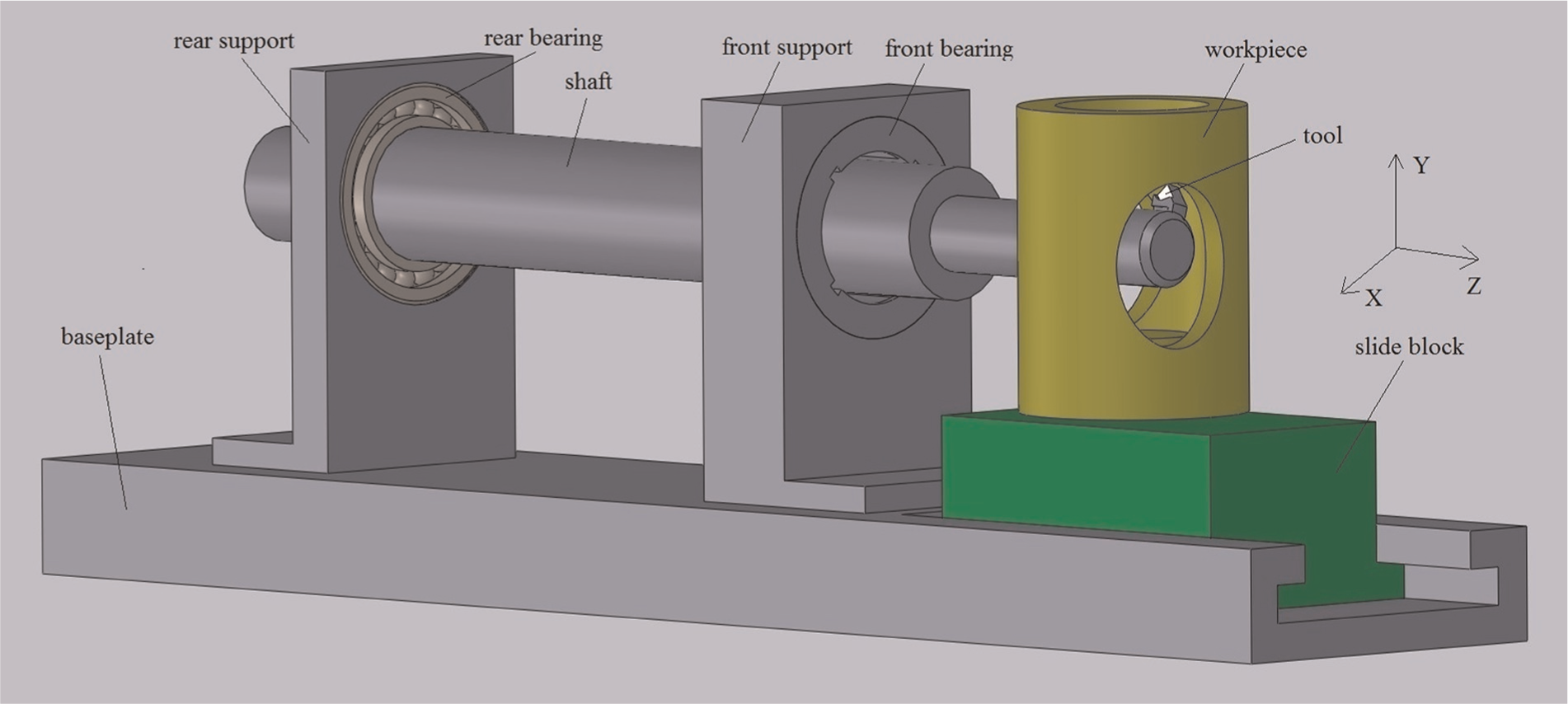
Schematic representation of the hydrostatic shaft system.
When the noncircular holes are machined, the shaft has two movements. The first movement is the shaft’s rotation around its axis line, and the second is the shaft’s swing (also called the revolution or precession) with the rear bearing center as fulcrum. When the shaft takes the two movements simultaneously, the expected elliptic orbit can be achieved in both the front bearing plane and the cutting point plane. When the workpiece moves along the Z-direction, the elliptic curved surface can be obtained, and by adjusting the range of the shaft’s procession, the varying elliptic curved surface can be achieved. Finally, the elliptical hole of workpiece can be machined.
For noncircular pin holes like those of the piston, the commonly used span 20 of ovality is 0.02–0.06 mm, and this ovality requirement can be met by hydrostatic bearing’s clearance.
The forming principle
Figure 2 is the forming schematic of tool nose orbit in the case of synchronous forward precession at time t. The two-dimensional diagram is located in the cutting plane of tool nose. The origin O of fixed coordinate system OXY is the intersection point of the bearing center line and the cutting plane. The point
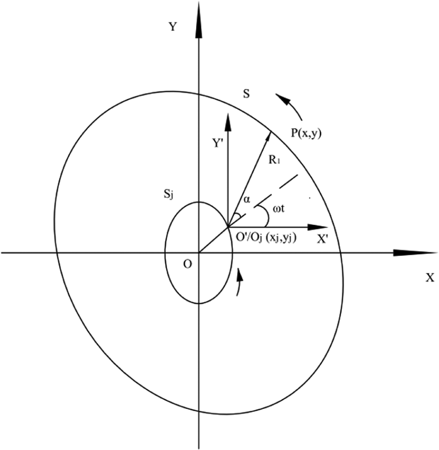
Schematic representation of the forming of tool nose orbit in the case of synchronous forward precession.
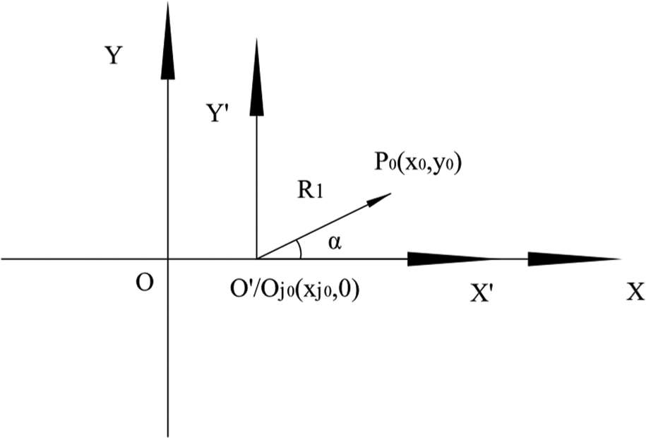
Schematic representation of the initial phase angle in the case of synchronous precession.
The rotation equations of tool nose
It is assumed that the tool nose rotates around point
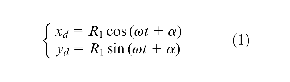
where
The synchronous revolution equations of shaft center
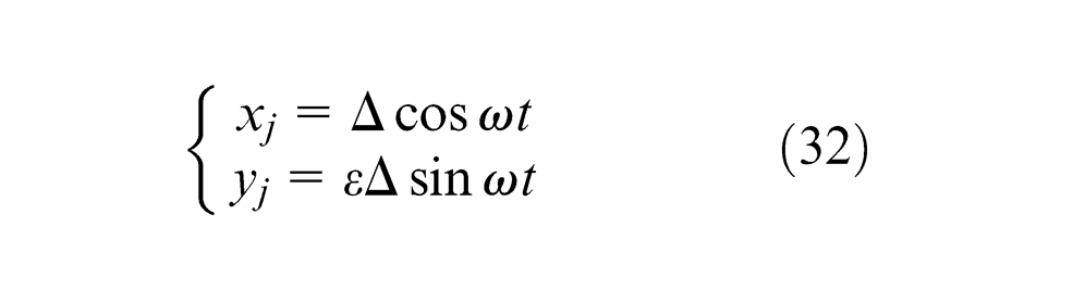
For a better description, it might as well first assume that the shaft center orbit is an ellipse whose semi-major and semi-minor axis lengths are
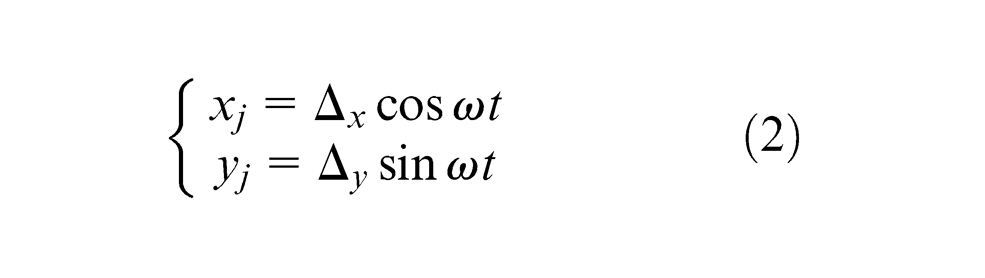
When
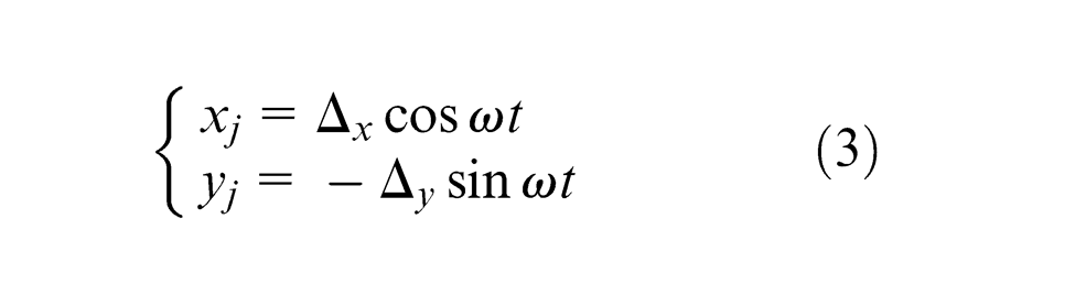
Combining equations (2) and (3), the general equation of the shaft center orbit can be expressed as
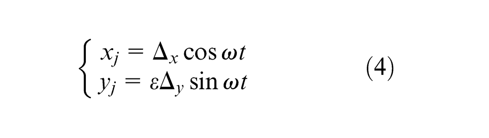
where
The synthesis motion equations
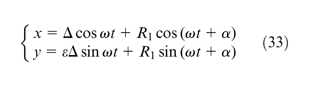
According to the principle of motion synthesis, the coordinate of the tool nose P in coordinate system OXY can be obtained and given as follows
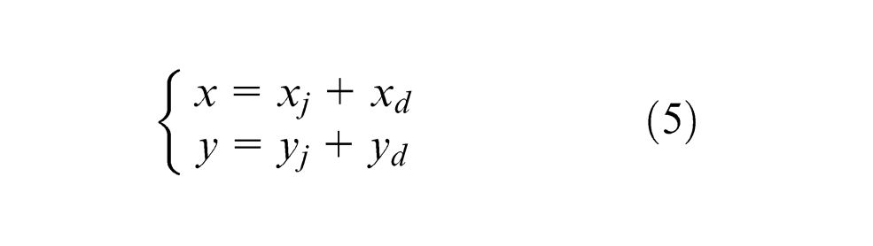
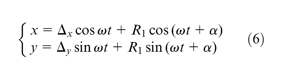
Substituting equations (1) and (2) into equation (5) yields the equations of tool nose orbit in the case of synchronous forward precession, which can be given as follows
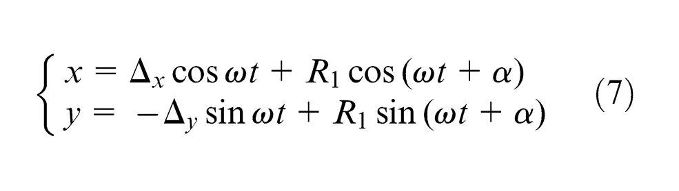
Similarly, the equations of tool nose orbit in the case of synchronous backward precession can be written as
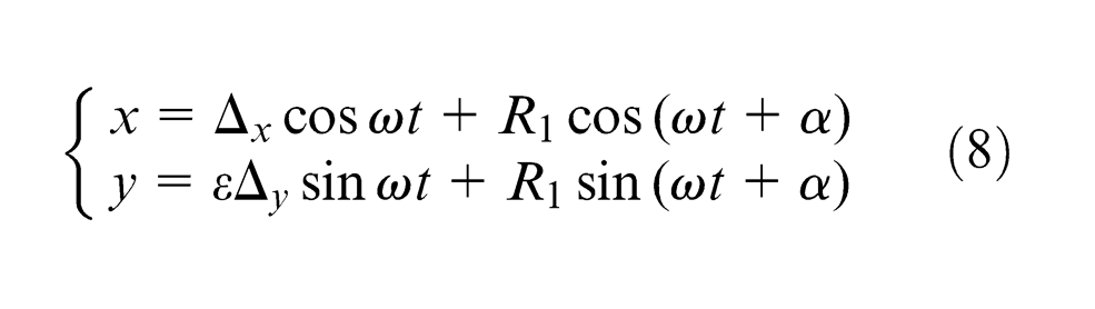
Combining equations (6) and (7), one obtains the general equation of the tool nose orbit as
Analysis of the movement forming methods
The type of the shaft center orbit varies with the values of
Analysis of synthesis motion of the tool nose orbit when the shaft center orbit is an ellipse (
)
The necessary conditions for the elliptic tool nose orbit
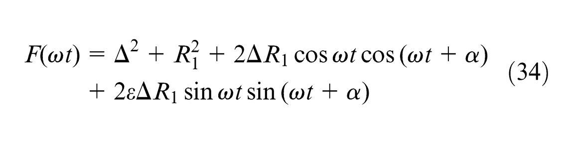
Defining

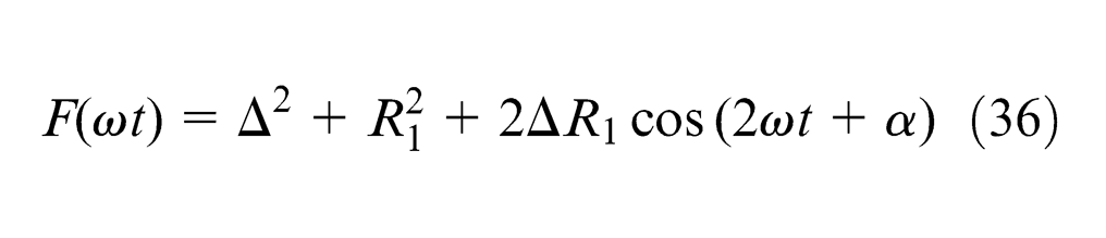
The necessary conditions for the elliptic tool nose orbit are as follows: (1) there exist two equal maximum values and two equal minimum values in the function
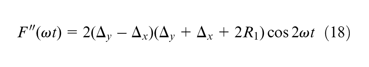
The existence and equivalence of the extreme values
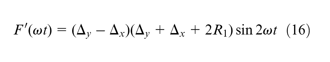
Substituting equation (8) into equation (9) and taking the first-order derivative of
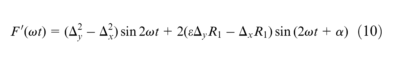
Setting
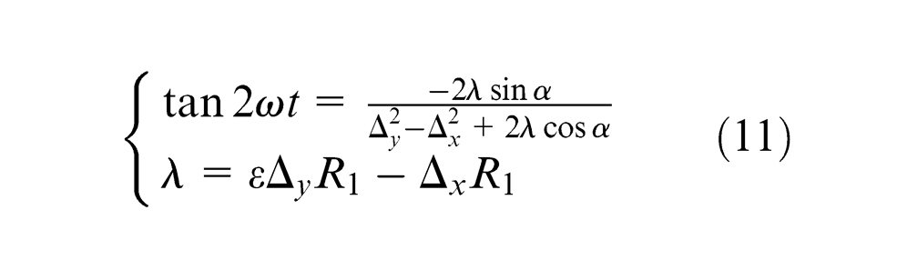
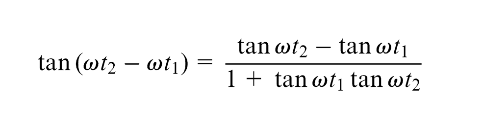
The double-angle formula of tangent can be written as

The solutions of equation
1. When
The general solutions of
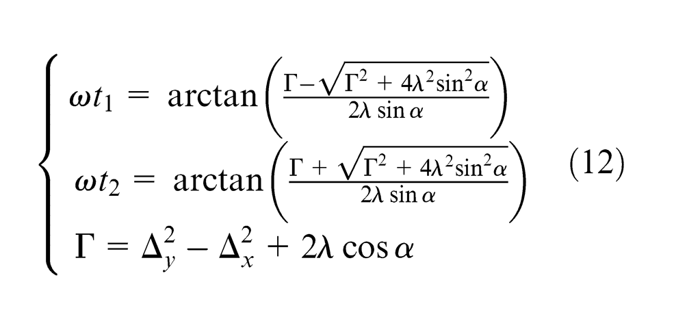
and

In order to judge whether the extreme value
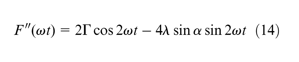
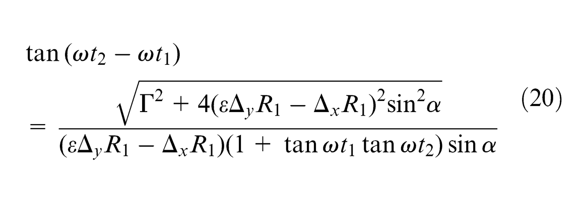
Combining equations (12) and (14), one can obtain equation (15) as (see Appendix 1)
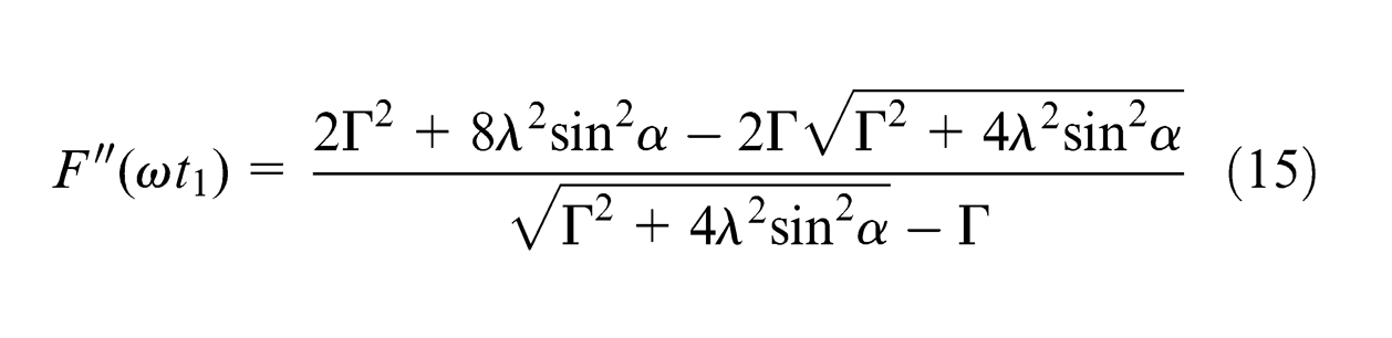
It can be proved that
From equations (12) and (13), it can be obtained that
2. When
Since the solutions of equation
Substituting
Since
Similarly, in order to judge whether the extreme value
Since it has been supposed that
Substituting
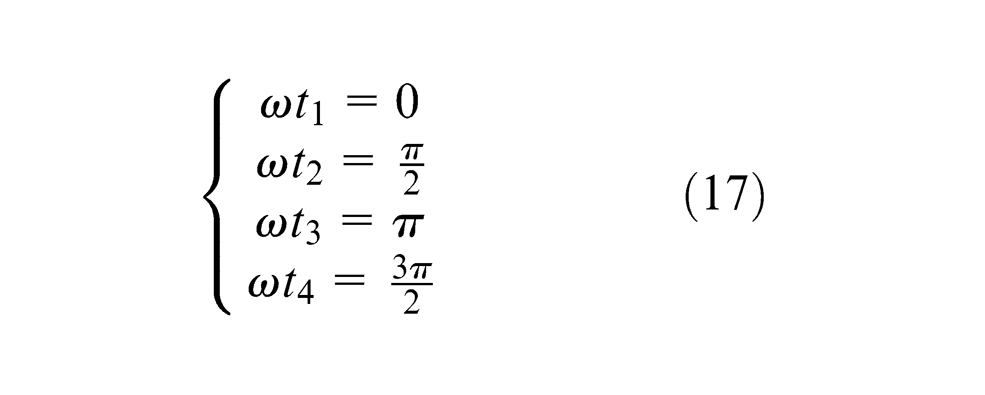
According to the above process, one obtains the particular solutions in the other three cases (see Appendix 2). The calculated results in four cases indicate that the particular solutions are same (i.e. equation (17)); the function
The first necessary condition for the elliptic tool nose orbit has been proved as above. The second necessary condition will be proved in the following part.
The phase relations of the extreme points
1. When
According to equations (12) and (13), it can be easily proved that the phase difference between two maximum points and the phase difference between two minimum points are both 180°. In the following part, we will prove that the phase difference between the maximum point (when
Equation (12) can be rewritten as
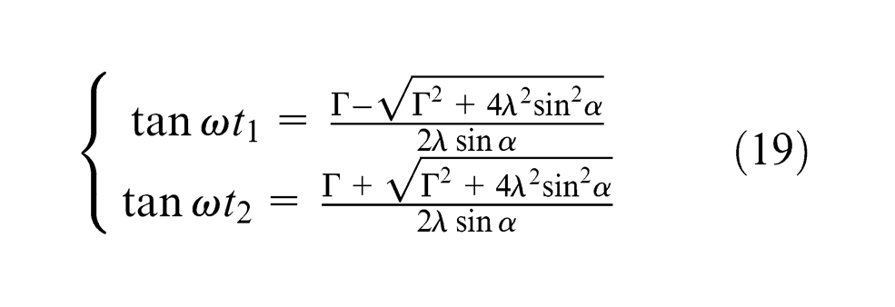
Using the formula of triangle transformation
yields
According to equation (19), it can be easily proved that equation

When
The two above expressions can be unified into
Similarly, when
2. When
According to equation (17), it can be proved that the phase difference between two maximum points and the phase difference between two minimum points are both 180° and that the phase difference between the maximum point (when
Thus, it has been fully proved that the necessary conditions for the elliptic tool nose orbit are tenable regardless the values of
The sufficient conditions and control equations for the elliptic tool nose orbit
Since the solutions of equation
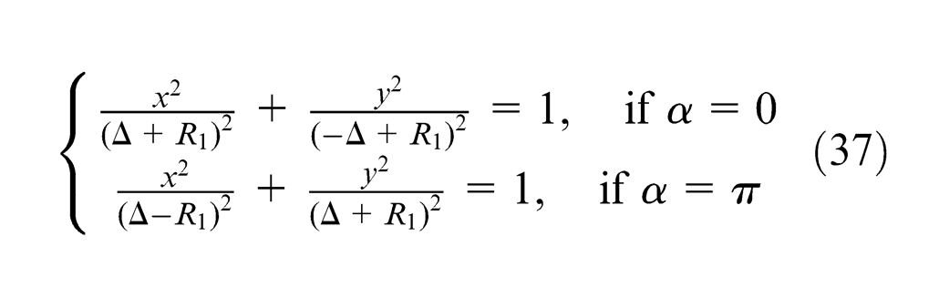
The sufficient conditions and control equations when
or
Since
Substituting
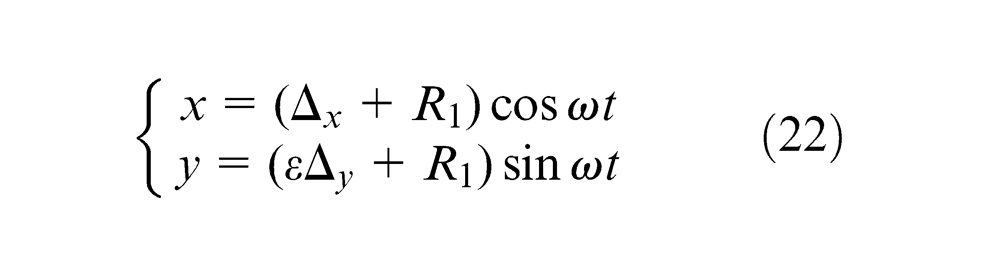
Similarly, when
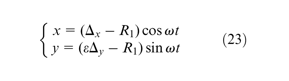
It can be found that the curves described by equations (22) and (23) are both standard ellipses whose semi-axes are in coordinate axes. The control equations of elliptic tool nose orbit can be written as
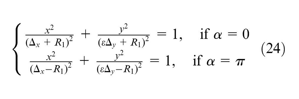
For the synchronous forward precession (
For the synchronous backward precession (
From equation (25), we can find the following conclusions.
When
When
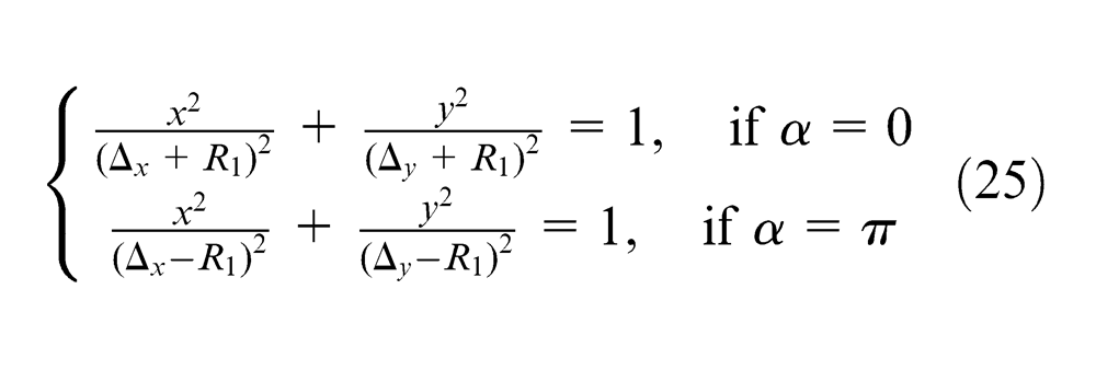
From equation (26), we can find the following conclusions.
When
When
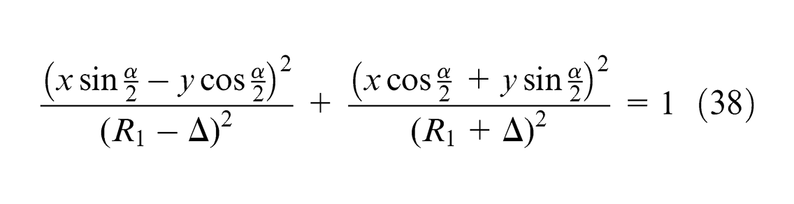
The sufficient condition and control equations when
and
If the curve generated by rotating clockwise the tool nose orbit around the origin by a certain degree is a standard ellipse (semi-axes are in coordinate axes), the tool nose orbit before this rotation must be an ellipse. That is the sufficient condition for the elliptic tool nose orbit when
Figure 4 is the schematic representation of the tool nose orbit under the situation of elliptic shaft center orbit.
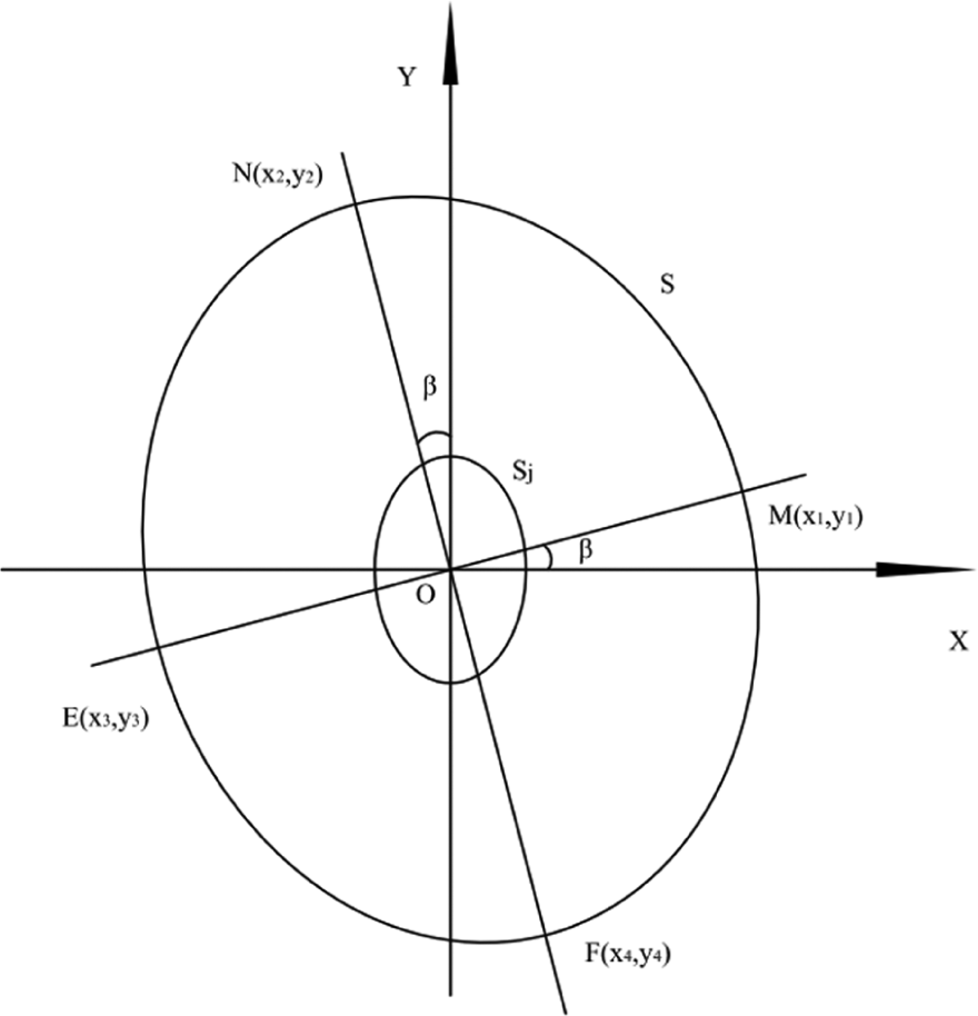
Schematic representation of the tool nose orbit when the shaft center orbit is an ellipse.
From the geometrical relationship represented by Figure 4, it can be obtained that
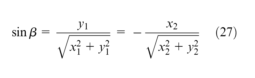
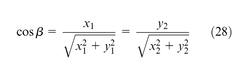
If the tool nose orbit described by equation (8) is rotated clockwise around the origin by
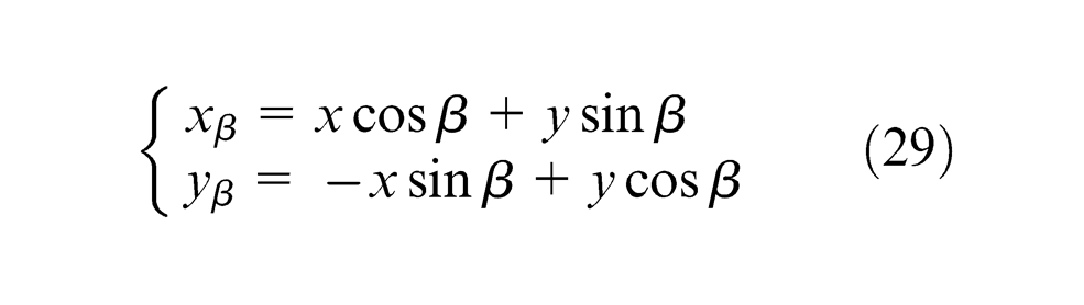
Substituting equations (27) and (28) into equation (29) and simplifying it yield (see Appendix 3)
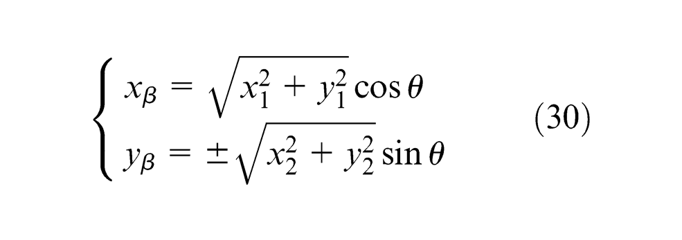
Obviously, the rotated curve described by equation (30) is a standard ellipse. So, the tool nose orbit is an oblique ellipse. Its semi-major axis
Thus, the sufficient condition for the elliptic tool nose orbit has been proved. The control equations of the elliptic tool nose orbit could be expressed as follows

Analysis of synthesis motion of the tool nose orbit when the shaft center orbit is a circle (
)
The parametric equations of the shaft center orbit become
where
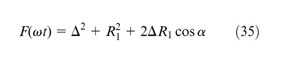
Similarly, defining
The simplified results of
Synchronous forward synthesis (
)
Equation (34) can be simplified as
Since the term of
Synchronous backward synthesis (
)
Equation (34) can be simplified as
According to the deducing steps mentioned in section “Analysis of synthesis motion of the tool nose orbit when the shaft center orbit is an ellipse (
1. When
Substituting
From equation (37), we can find the following conclusions.
When
2. When
According to the proving process of section “Analysis of synthesis motion of the tool nose orbit when the shaft center orbit is an ellipse (
Analysis of synthesis motion of the tool nose orbit when the shaft center orbit is a line segment in Y-axis (
and
)
Substituting
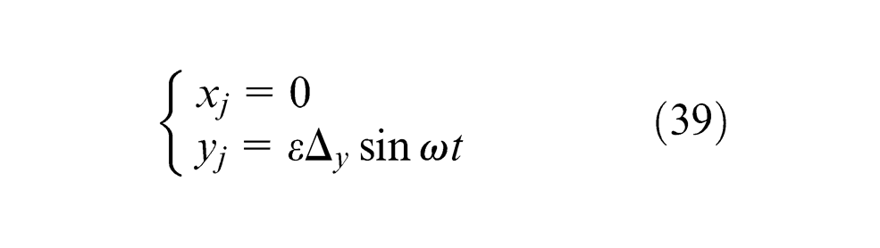
By substituting
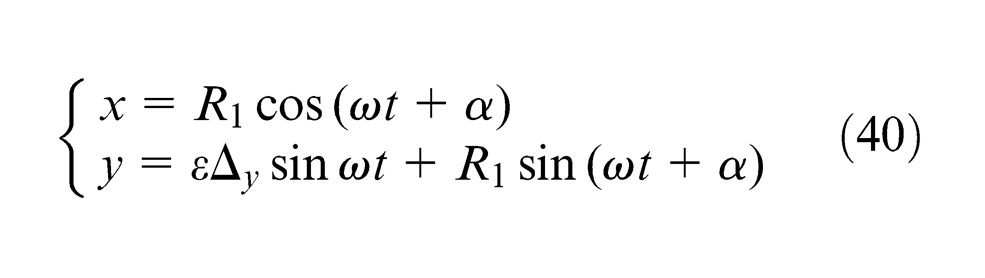
Since this is just a special case of the situation in which the shaft center orbit is an ellipse, the same deducing steps can be adopted while
1. When
By substituting
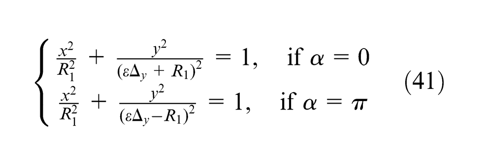
Obviously, when
2. When
According to the proving process of section “Analysis of synthesis motion of the tool nose orbit when the shaft center orbit is an ellipse (
Analysis of synthesis motion of the tool nose orbit when the shaft center orbit is a line segment in X-axis (
and
)
By substituting
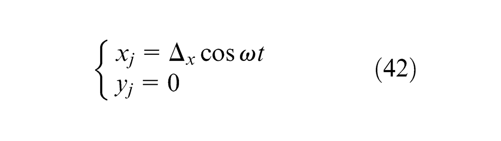
The parametric equations of the tool nose orbit can be obtained by equation (43)
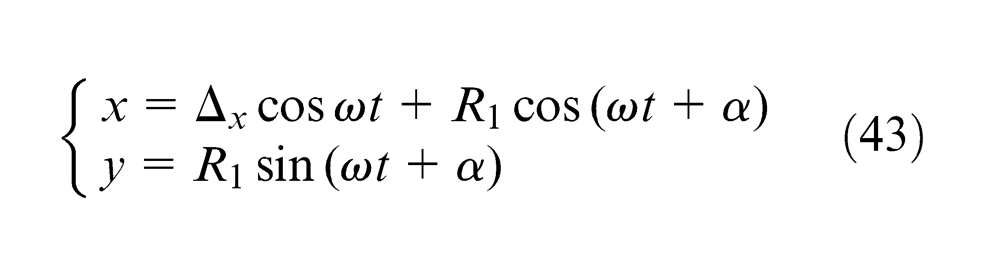
Since this is just another special case of the situation in which the shaft center orbit is an ellipse, the tool nose orbit is always an ellipse regardless of the values of
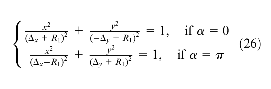
When
By substituting
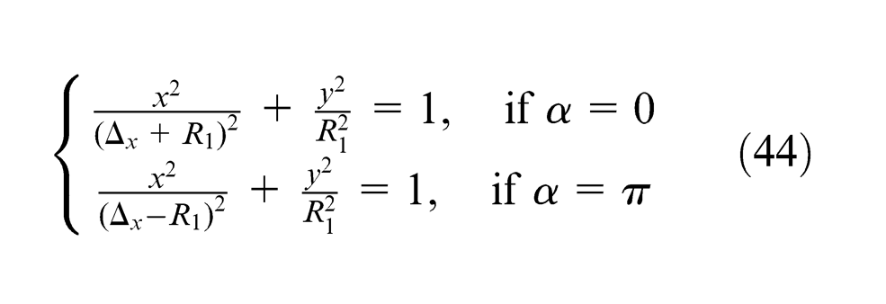
Obviously, when
When
According to the proving process of section “Analysis of synthesis motion of the tool nose orbit when the shaft center orbit is an ellipse (
Conclusion
This article presents new movement forming methods of machining elliptic-shaped holes, and detailed analyses of the movement forming methods are given. Necessary conditions and sufficient conditions for forming elliptic tool nose orbit are studied under the conditions of two motion modes (synchronous forward precession and synchronous backward precession) and four shaft center orbits (ellipse, circle, line segment in X-axis, and line segment in Y-axis). The conclusions can be summarized as follows.
When the shaft center orbit is an ellipse or a line segment in coordinate axis (X- or Y-axis), both the synchronous forward precession and synchronous backward precession can form the elliptic tool nose orbit. When the shaft center orbit is a circle, only the synchronous backward precession can form the elliptic tool nose orbit. Therefore, the machining of elliptic holes can be realized by controlling the shaft center orbit. This article presents control equations of the tool nose orbits under multiple conditions.
The initial phase angle of the tool nose has a great influence on the phase of the elliptic tool nose orbit. When initial phase angle
When the shaft center orbit is an ellipse, both the synchronous forward precession and synchronous backward precession can form elliptic tool nose orbit. And the features are summarized as follows.
When the precession mode is synchronous forward precession and When the precession mode is synchronous backward precession and
When the shaft center orbit is a circle, only motion synthesis of backward precession can form elliptic tool nose orbit. The features are summarized as follows.
When
When the shaft center orbit is a line segment in axis, both the synchronous forward precession and synchronous backward precession can form elliptic tool nose orbit. And characteristics are summarized as follows.
When the shaft center orbit is a line segment in Y-axis and When the shaft center orbit is a line segment in X-axis and
The matching features of shaft center orbit and the tool nose orbit mentioned above can provide multiple choices for the control realization. Their specific implementations need further study.
Footnotes
Appendix 1
The process of transforming equation (14) into equation (15) is as follows.
Since
Substituting equation (45) into equation (14), one can obtain the expression of
Substituting the expression of
Substituting equation (47) into equation (46) gives
Appendix 2
The particular solutions in the other three cases in part 2 (when
Substituting
Since the radius
Similarly, the particular solutions of
Similarly, the particular solutions of
Appendix 3
The process of transforming equation (29) into equation (30) is as follows.
Substituting equations (27) and (28) into equation (29) yields
Substituting equation (8) into equation (49) gives
Substituting
Similarly,
Since
Equations (51) and (53) can be rewritten as follows
Appendix 4
The elements of
Substituting these eight equations into equation (50) and combining with
Declaration of conflicting interests
The authors declare that there is no conflict of interest.
Funding
This research was supported by National Natural Science Foundation of China (No. 51075242 and No. 51375275). It was also supported by the Graduate Independent Innovation Fund of Shandong University (No. yzc12125).