
Abstract
In order to realize the machining of elliptical holes, the article researches control simulation of shaft center movement orbit using Eulerian method. A new hydrostatic bearing and a hydraulic control system are proposed, and quantitative relation between the expected shaft center coordinates and spool displacement of electro-hydraulic servo valve is studied. With the Eulerian method, open-loop control orbit of shaft center is simulated. And the simulation results indicate that open-loop control method not only controls shaft center movement to form ellipse orbits but also has strong robustness against dynamic disturbing force or instantaneous static disturbing force. This article lays theoretical basis for machining of elliptical holes.
Introduction
As mechanical equipment power and rotating speed increase, the load strength the hole in mechanical equipment has to stand becomes increasingly high. The traditional shape of a hole is a circle, but the inner side of the circular hole has severe stress concentration, which reduces the hole’s working life. Comparing with circular holes, non-circular holes have stronger fatigue strength. Elliptical hole, such as pin hole of piston,1,2 is one of the non-circular holes in common use. There are many traditional machining methods for the elliptical hole. The German KS corporation adopts mechanical coping apparatus to machine elliptical holes.3,4 The experiment indicates that the machining precision of elliptical hole with that method is at micron level. Zhang and Hu 5 use electromagnetic actuation device for boring elliptical holes. The boring feeding is controlled by electricity in the actuation device. Gosiewski et al. 6 also present the machining method of non-circular holes based on the electromagnetic actuation and conduct the fine boring experiments of elliptical pin holes. Wilson et al. 7 and Beach 8 design the fast tool system for machining piston hole, and the tool system adjusts tool feed rate with piezoelectric actuator. George 9 also proposes a type of fast tool system based on piezoceramic material, and deformable boring bar is adopted in fast tool system. By controlling coil current to change the length of giant magnetostrictive material, Zhang et al. 10 use the bending deflection of boring bar to realize the boring of elliptical hole. Moller 11 put forward a new kind of magnetic-suspension spindle system, which can be applied to boring non-circular holes with any shape. Later, Kim et al. 12 also use a magnetic bearing to control the displacement of the rotor for boring the non-circular hole and carry out some experiments using the boring machine developed by themselves. The cutting error is within 2 mm at the rotational speed of 1500 r min−1.
Now, there exist many boring methods for elliptical holes. But it can be found that these methods have some disadvantages, such as complex mechanical composition, relatively small installation space for boring rod and tough accuracy control. So it is necessary to quest a much better boring method. A new machining method for elliptical holes is presented in the literature, 13 and the conclusion is obtained: when the shaft center revolution orbit is an ellipse, the motion synthesis between shaft center revolution orbit and tool rotation orbit can form the elliptical tool nose orbit. And thus, the machining of elliptical hole can be realized. So, as long as the shape of shaft center orbit is an expected ellipse, the elliptical tool nose orbit can be obtained. This article aims at controlling shaft center movement orbit. In this article, open-loop control simulation of shaft center orbit is carried out, which proves the feasibility of hydraulic control scheme and lays theoretical basis for the application of new machining method. 13
At present, the main simulation methods of shaft center orbit are Eulerian method, 14 Hahn method,15,16 Holland method 17 and mobility method. 18 Eulerian method is a dynamics simulation method, but the other three ones are static methods which ignore the accelerated speed of shaft. Comparing with those three methods, the solution of Eulerian method is much better in consistency with the actual situation and the simulation precision of shaft orbit is much higher. Based on those advantages, many experts use the Eulerian method19,20 to simulate the shaft center orbit.
In this article, a new type of hydrostatic bearing is proposed, and the corresponding hydraulic control scheme is presented as well. The quantitative relation between the shaft center coordinates and bearing load capacity is obtained. On the basis of previous work,21,22 using flow continuity equation, one can get the analytical expressions of recess pressure and bearing load capacity. Then, the quantitative relation between load capacity and spool displacement of electro-hydraulic servo valve can be obtained. This article studies open-loop control simulation of shaft center movement orbit with Eulerian method. The simulation results manifest that open-loop control method can control shaft center movement to form ellipses with different ovalities and has strong robustness against dynamic disturbing force or instantaneous static disturbing force. This article provides theoretical foundation for practical application of new movement forming method.
Analysis
New hydrostatic bearing and corresponding hydraulic control scheme
Because the machining of elliptical holes is based on hydrostatic bearing control, the hydrostatic bearing is an important part of hydraulic control system. If bearing is a common four-recess hydrostatic bearing with circumferential return chute, hydraulic control system has disadvantages of control delay and low control sensitivity because of big recess area and big flow. In order to solve these problems, this research designs a new hydrostatic bearing with new recess structure, and the structure details are presented in Figure 1. New hydrostatic bearing has four big pockets, and inside each big pocket (it is named as load pocket), there is a small pocket (it is named as control pocket). Because the small pocket is inside the big pocket, this new structure bearing is named as pocket-nest hydrostatic bearing. There is isolation surface between control pocket and load pocket. Two kinds of pockets have their own oil supply holes separately, and the supply pressure of control pocket is higher than that of load pocket. One of load pocket’s design purposes is to offset the shaft gravity, and the other purpose is to increase system stiffness. Comparing with the pocket of common hydrostatic bearing, the control pocket has smaller pocket area and smaller flow, so the design of control pocket can improve the system control sensitivity and control speed.
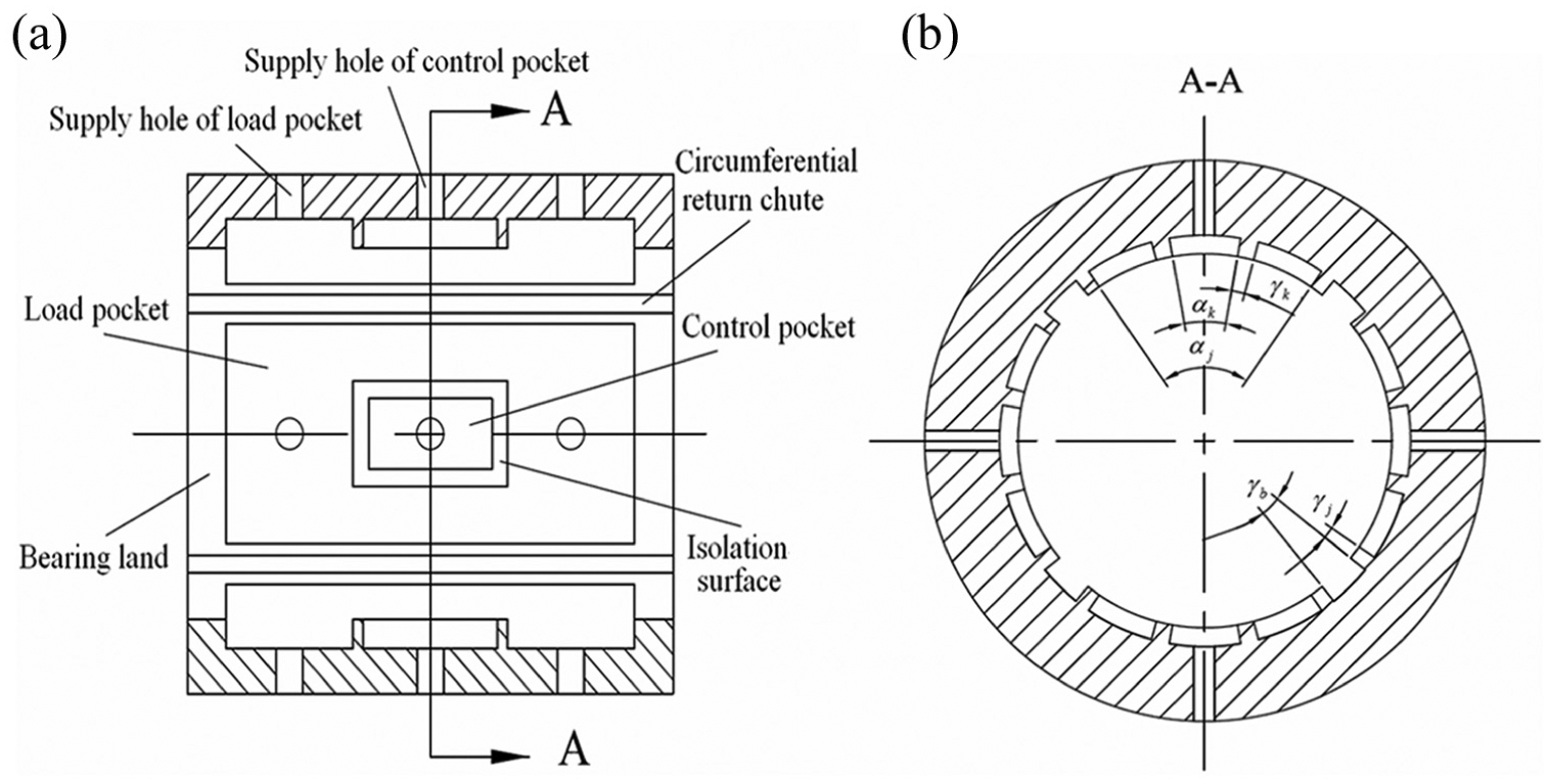
(a) Structure of pocket-nest hydrostatic bearing and (b) A-A section view.
Based on the previous work,
13
this article uses open-loop control method to control shaft center movement orbit and make it an ellipse, which synthesizes with rotation of the tool nose around shaft center. Thus, the machining of elliptical hole can be achieved. New hydraulic control system is designed based on the structure of pocket-nest hydrostatic bearing, and its details are presented in Figure 2. Hydraulic system can control the shaft center movement orbit by changing flow and pressure of control pocket. In Figure 2, four restrictors are all capillary restrictors, and four servo valves are all electro-hydraulic servo valves. Because the new bearing has two kinds of pockets (i.e. load pocket and control pocket), hydraulic system has two kinds of oil supply circuits ((1) lubricant flows into control pocket through electro-hydraulic servo valve and (2) lubricant flows into load pocket through capillary restrictor). To ensure the pressure of control pocket to be higher than that of load pocket, the supply pressure
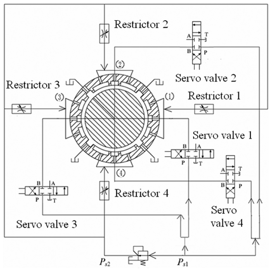
Hydraulic control system.
The principle to realize the expected elliptical shaft center movement orbit using this hydraulic control system is as follows: in original state, servo valves 1 and 3 have the same spool displacement. When spool displacement of servo valve 1 becomes bigger and that of servo valve 3 becomes smaller, the pressure of control pocket 1 becomes bigger and that of control pocket 3 becomes smaller. Then, pressure difference between control pockets 1 and 3 generates thrust to push the shaft and the shaft center moves in the left direction. Conversely, the pressure difference makes the shaft center move in the right direction. In a similar way, the active control of servo valves 2 and 4 can control y-coordinate of shaft center. So, by active control of four servo valves, pressure difference can push the shaft and make the shaft center movement orbit an expected ellipse.
In order to realize the control of shaft center movement orbit, this research should at first get quantitative relation between the shaft center coordinates and bearing load capacity. The quantitative relation between bearing load capacity and spool displacement should also be solved. Then, the quantitative relation between the shaft center coordinates and spool displacement is obtained.
Quantitative relation between shaft center coordinates and bearing load capacity
Suppose the parameter equations of the shaft center’s expected ellipse orbit are
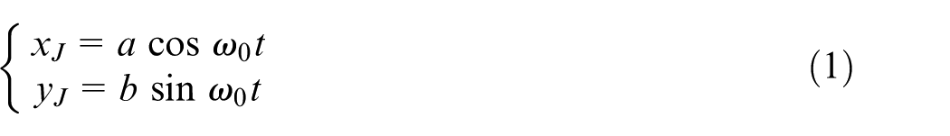
where
Taking the first-order derivative of equation (1) gives
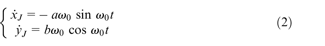
where
Taking the second-order derivative of equation (1) gives
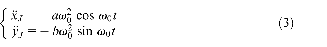
where
When the shaft moves inside the bearing, the force analysis of the shaft is presented in Figure 3. From Figure 3, the kinetic equations of the shaft can be obtained as
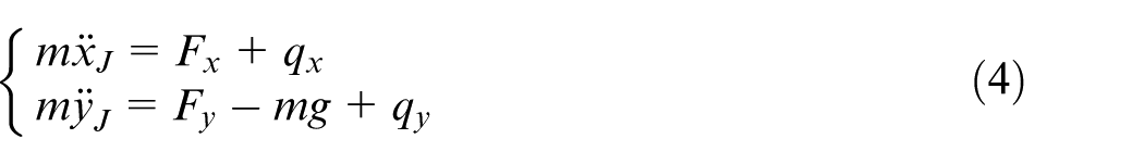
where m is the shaft mass, g is the gravitational acceleration,
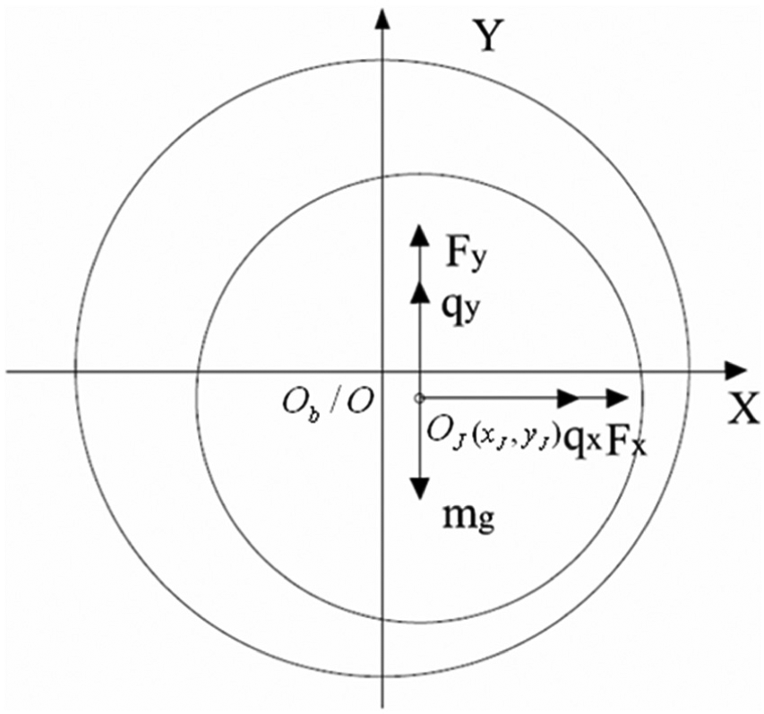
Force analysis of shaft.
Combining equations (3) and (4), one can obtain the bearing load capacity’s expressions
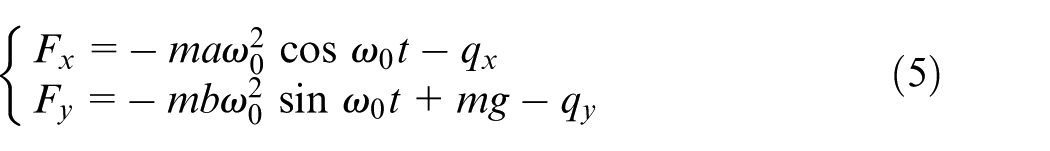
And the dimensionless expressions of equation (4) are
where
Quantitative relation between bearing load capacity and spool displacement
Based on the previous work,21,22 when the hydrostatic bearing has small bearing land, hydrodynamic effect on bearing land is very weak and can be neglected, and oil film force on bearing land is obtained using linear valuating method, and then analytical expressions of recess pressure can be solved using flow continuity equation. Moreover, from the literature, 22 the analytical expression of recess pressure has not only a wide application range but also a high computational accuracy. Because bearing land and isolation surface of new hydrostatic bearing in this article are both narrow, their hydrodynamic effect is weak and can be nearly ignored. Then, static performance parameters (such as recess pressure, flow of control pocket, and load pocket) can be solved without considering hydrodynamic effect. Analytical expressions of recess pressure and bearing load capacity are obtained using flow continuity equation as well as Gauss–Legendre integral formula, and the deduction details can be seen as follows.
The pocket-nest hydrostatic bearing has eight pockets; so there are eight flow continuity equations, as
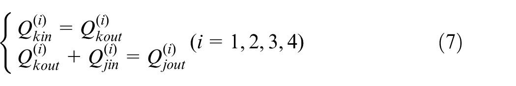
where
Using non-dimensional expression
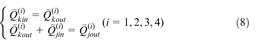
where η is the dynamic viscosity of lubricant.
Flow of control pocket
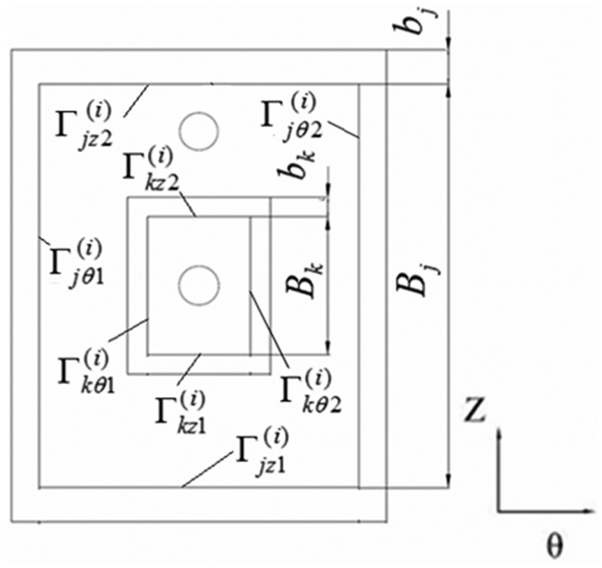
In Figure 4, the flow of lubricant flowing out of ith control pocket consists of two parts, that is, circumferential flow (
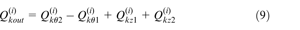
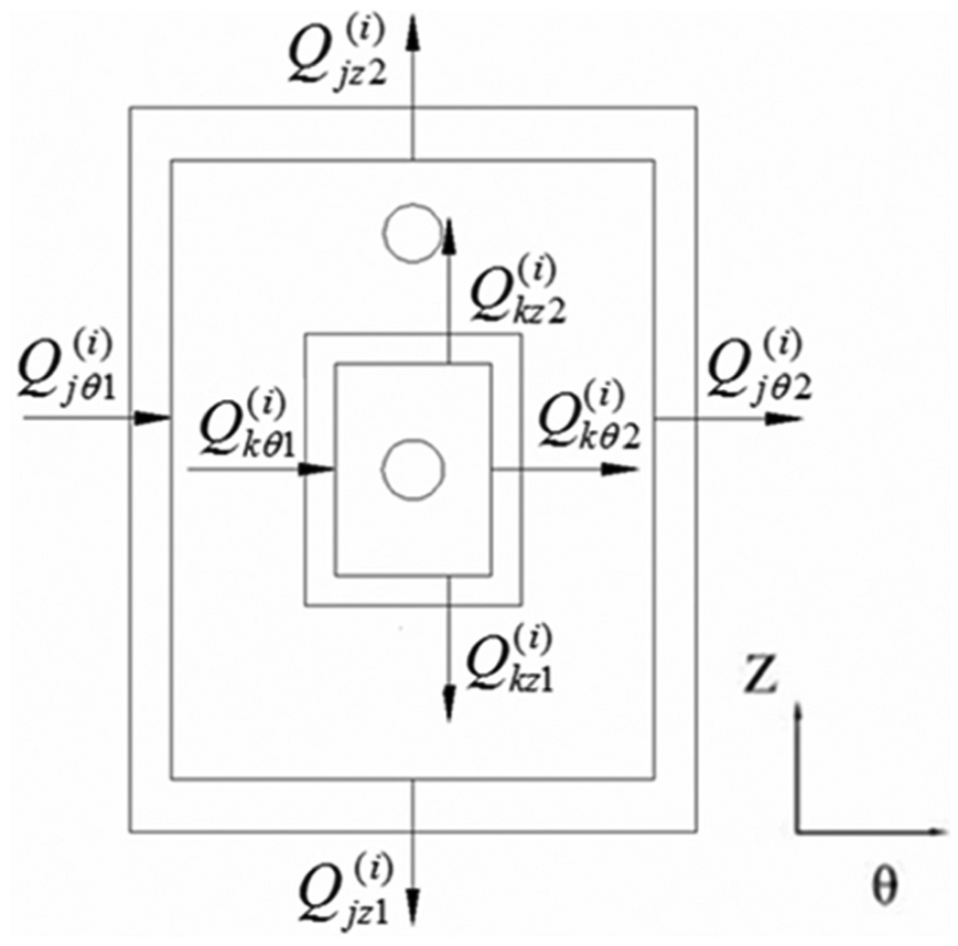
Schematic diagram of boundary flow of pocket.
The flow of lubricant flowing through circumferential boundaries (
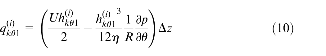

where
Substituting the equations of pressure gradient into equations (10) and (11) gives the flow of lubricant flowing through circumferential boundaries (
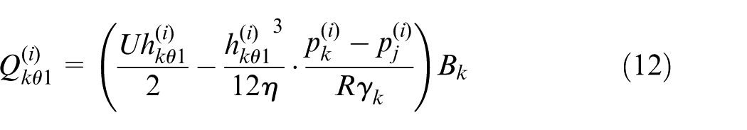
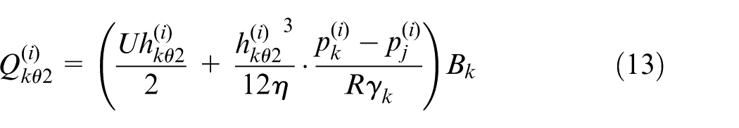
According to the non-dimensional equation
where
Schematic diagram of boundary of pocket.
Flow of lubricant flowing through axis boundaries of control pocket at per unit time is
where
According to geometrical relationship,
21
there exists equation
where
Function
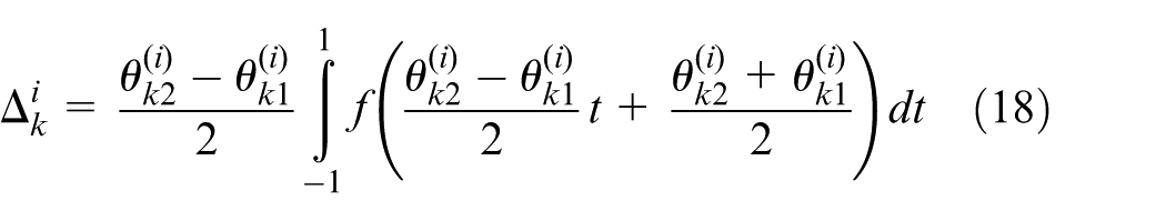
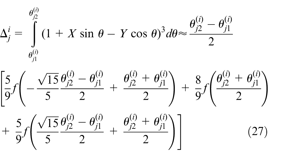
The three-point Gauss–Legendre integral formula 22 can be written as
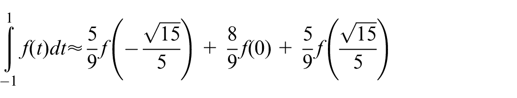
Using three-point Gauss–Legendre integral formula to solve variable
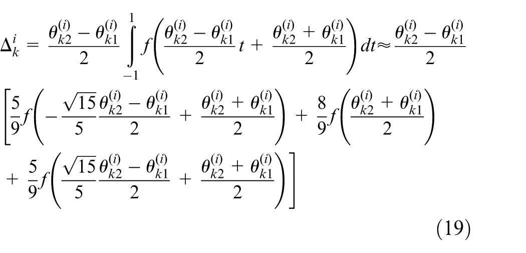
Equation (19) can be used to approximately solve the value of definite integral, so equation (17) is changed into
Substituting equations (14), (15), and (20) into equation (9) gives
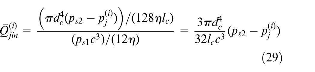
Flow of lubricant flowing into control pocket through electro-hydraulic servo valve is
where
Flow of load pocket
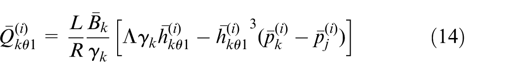
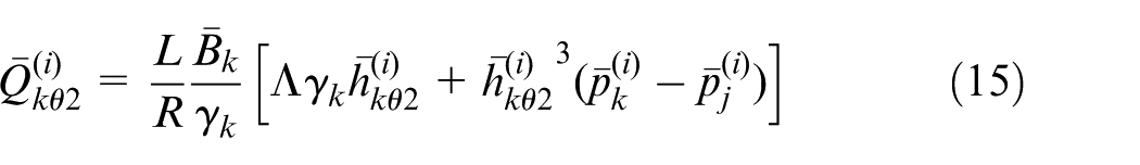
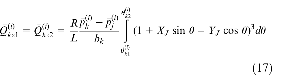
In a similar way, based on Figure 4, the flow equation of lubricant flowing out of ith load pocket is written as
where the flow equations for lubricant flowing through circumferential boundaries
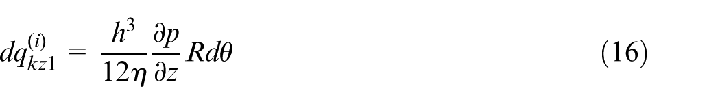
The flow of lubricant flowing through axial boundaries
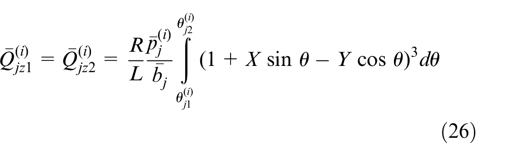
where (
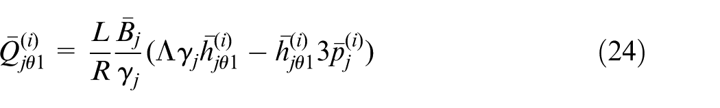
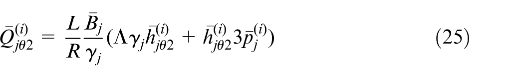
Using three-point Gauss–Legendre integral formula to approximately solve the value of definite integral in equation (26) yields
Substituting equations (24)–(27) into equation (23) yields
Non-dimensional flow of capillary restrictor is
In the equation above,
Analytical expressions of recess pressure and load capacity
Substituting equations (21), (28), and (29) into equation (8) can produce flow continuity equation of the ith load pocket, as
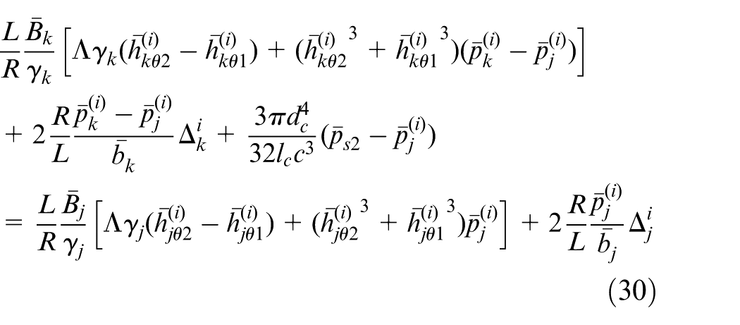
Suppose
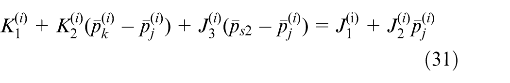
The expression of control pocket pressure is obtained by solving equation (31), that is
Substituting equations (21) and (22) into equation (8), one can obtain the flow continuity equation of control pocket
Solving equation (33) yields the other expression of control pocket pressure, as

Combining equations (32) and (34) can give
Suppose
exists, equation (35) can be simplified as
From equation (36), analytical expression of load pocket pressure can be obtained as
Summarize pressure expressions of load pocket and control pocket as
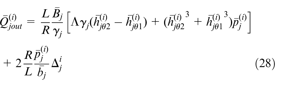
For the computational convenience, only through considering pressure of load pocket and control pocket (without considering the pressure of bearing land and isolation surface), can this research get components of load capacity in the directions of x and y, and those components are expressed as
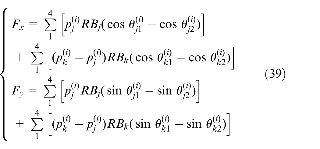
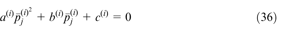
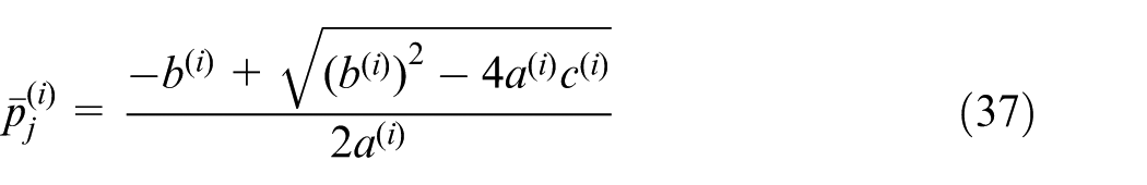
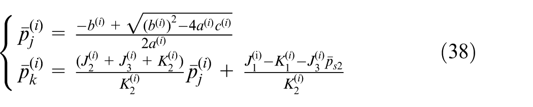
If the value of


where
Eulerian method
Combining equations (5), (39), (40), and (41) yields quantitative relation between the expected shaft center orbit coordinates and spool displacement of electro-hydraulic servo valve. Using obtained spool displacement parameters and Eulerian method, this research can simulate shaft center’s open-loop control orbits.
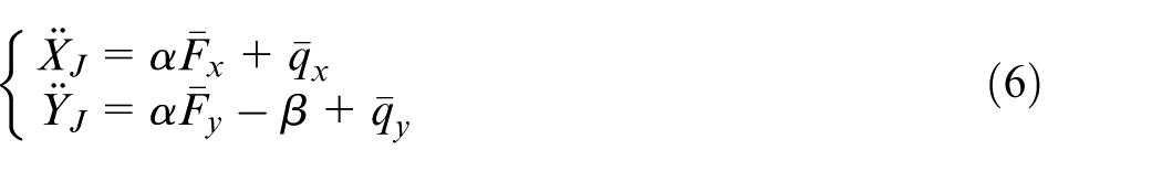
The equations of Eulerian method are


where
The computing steps of Eulerian method are as follows:
Setting the value of external loads
Setting the value of the initial shaft center location coordinates
Substituting the value of
Valuing
Using the next shaft center location coordinates
Results
First, an example is used to demonstrate the change law of system control parameter (i.e. spool displacement of four electro-hydraulic servo valves) when shaft center movement orbit is an ellipse.
Suppose non-dimensional equations of the expected elliptical orbit of shaft center as
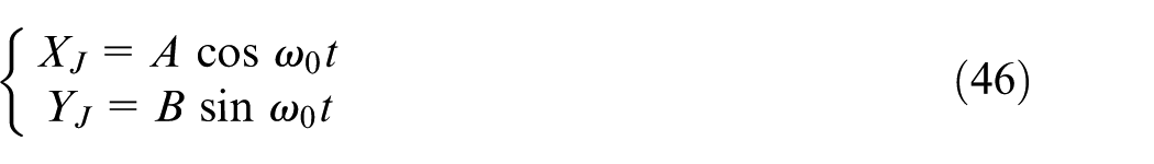
where
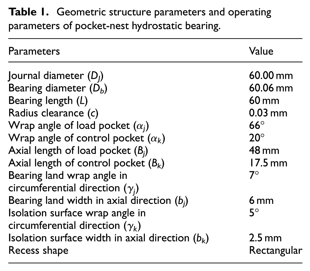
Structure parameters of pocket-nest hydrostatic bearing are shown in Table 1. The capillary restrictor diameter
Geometric structure parameters and operating parameters of pocket-nest hydrostatic bearing.
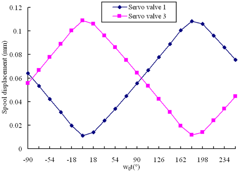
Change law of spool displacement of servo valves 1 and 3.
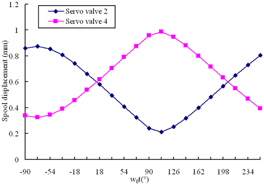
Change law of spool displacement of servo valves 2 and 4.
In Figures 8–16, (X, Y) and (ΔX, ΔY) are the non-dimensional coordinates, that is, the units of the axes in these figures are non-dimensional. The equations
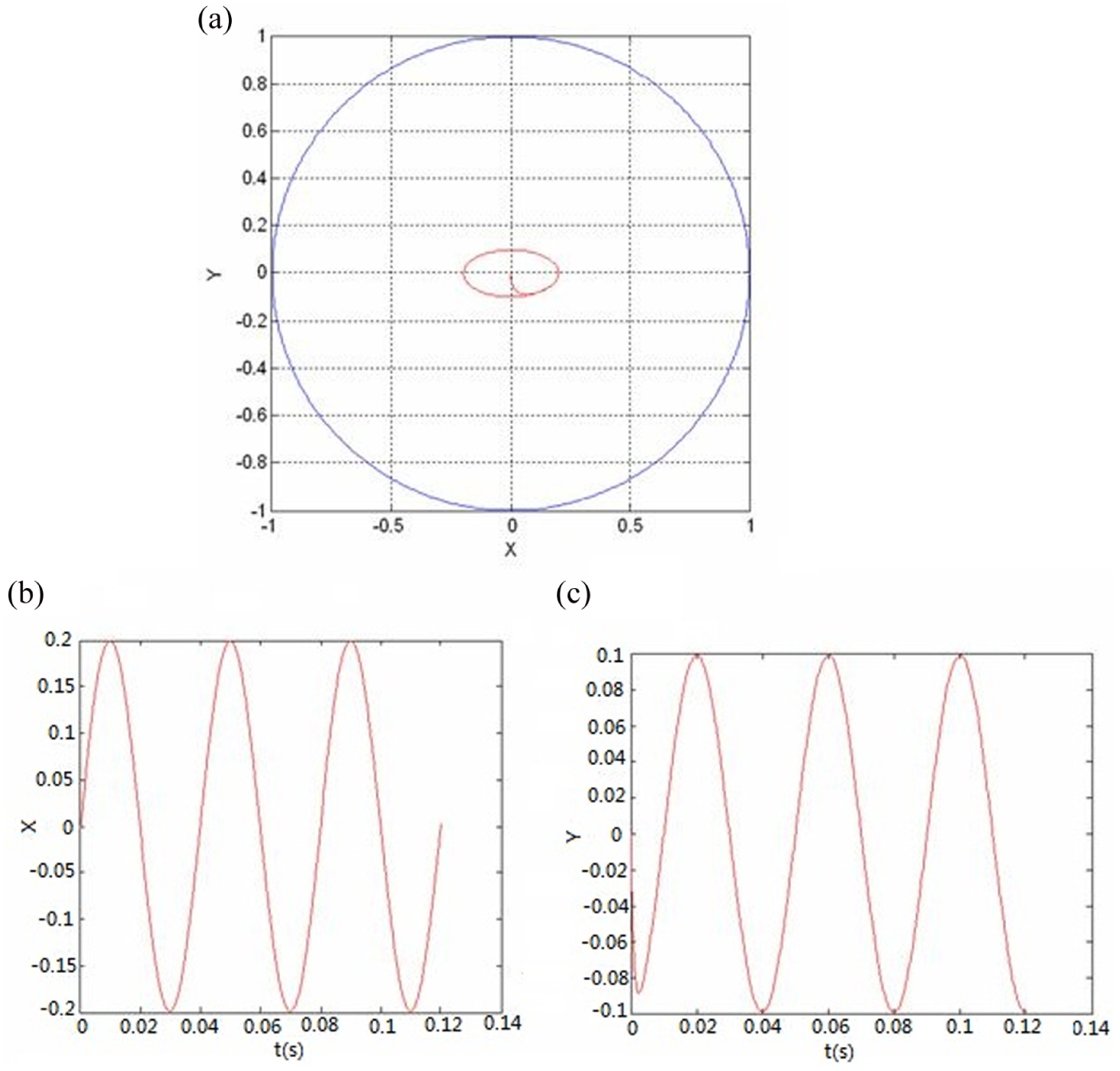
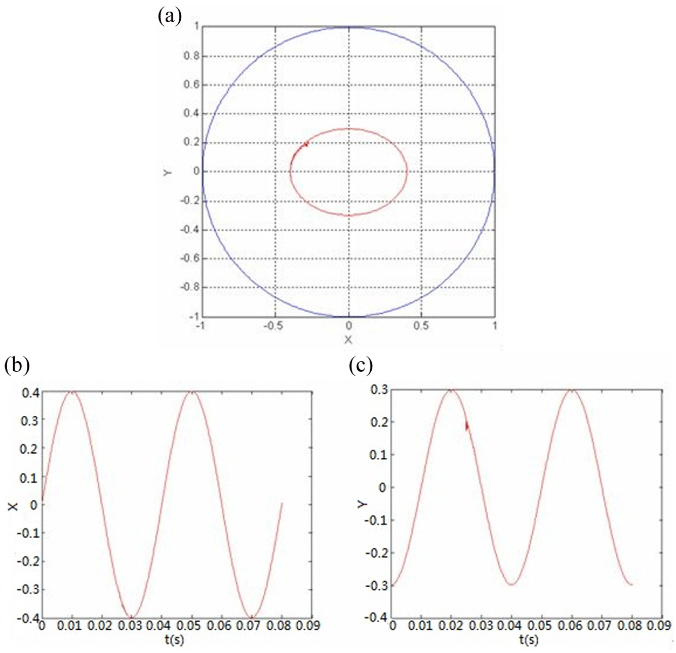
(a) Open-loop control simulations of shaft center movement orbit (A = 0.2, B = 0.1), (b) X-coordinate of shaft center, and (c) Y-coordinate of shaft center.
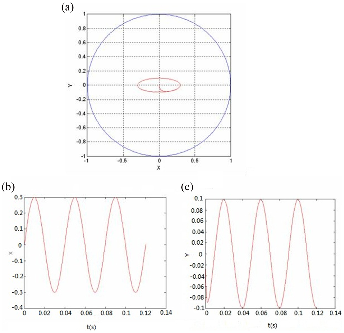
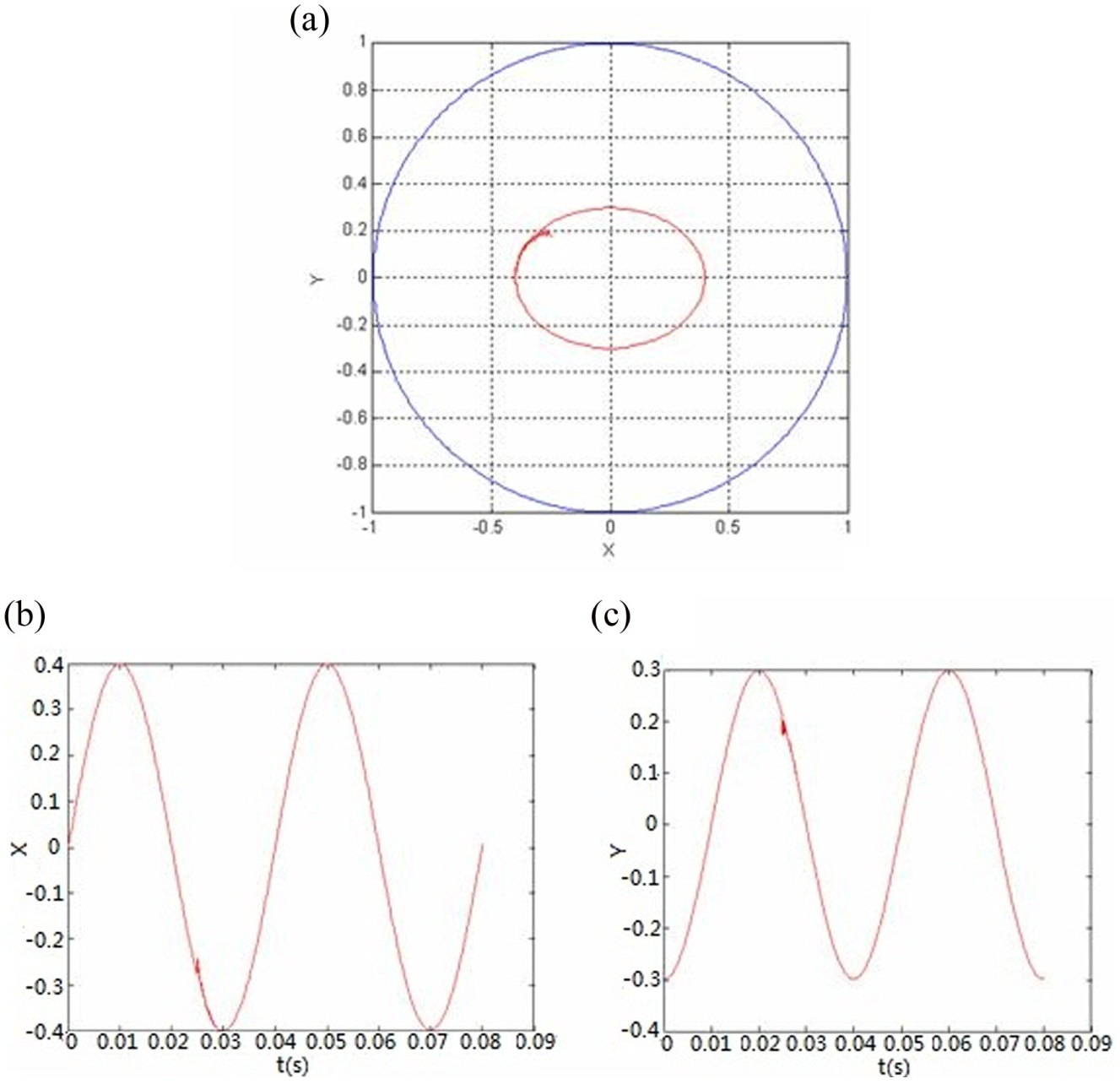
(a) Open-loop control simulations of shaft center movement orbit (A = 0.3, B = 0.1), (b) X-coordinate of shaft center, and (c) Y-coordinate of shaft center.
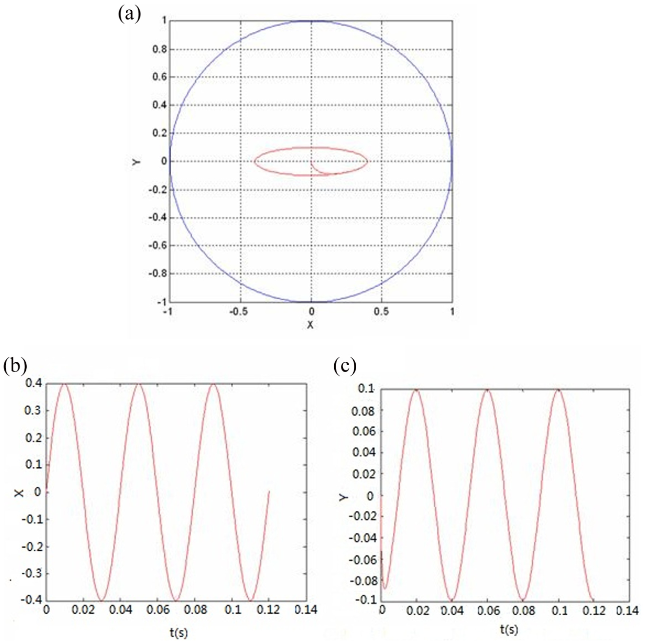
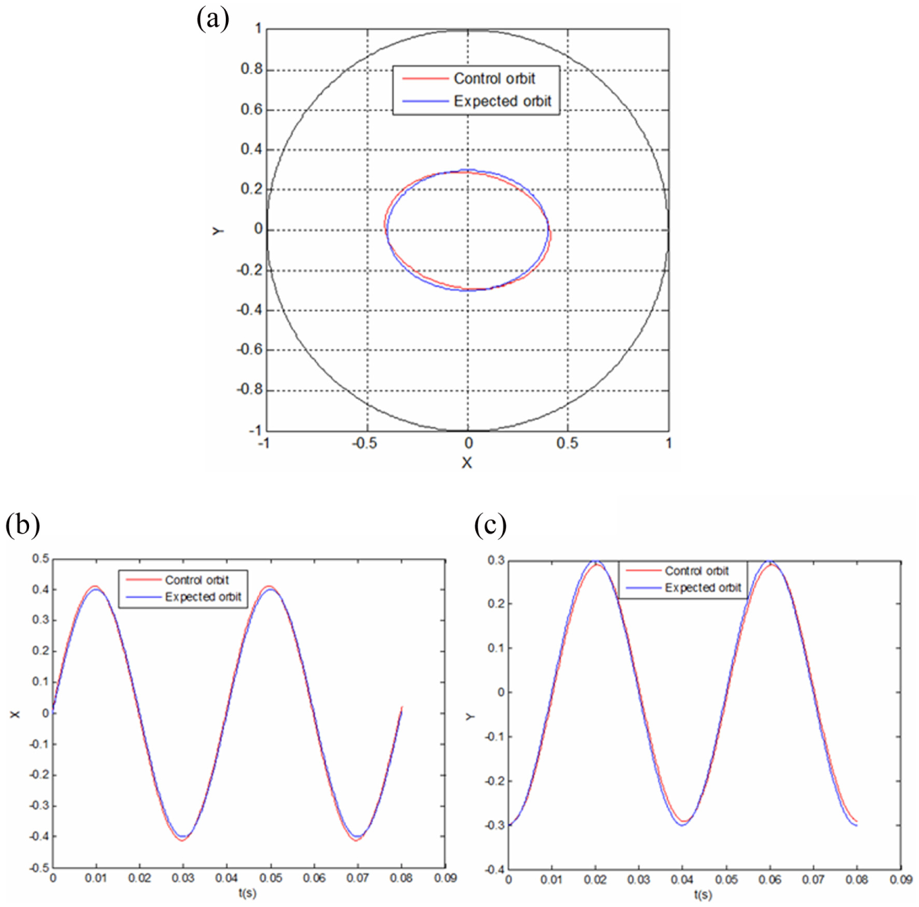
(a) Open-loop control simulations of shaft center movement orbit (A = 0.4, B = 0.1), (b) X-coordinate of shaft center, and (c) Y-coordinate of shaft center.
(a) Open-loop control simulations of shaft center movement orbit (qx = 500 N), (b) X-coordinate of shaft center, and (c) Y-coordinate of shaft center.
(a) Open-loop control simulations of shaft center movement orbit (qy = −500 N), (b) X-coordinate of shaft center, and (c) Y-coordinate of shaft center.
(a) Open-loop control simulations of shaft center movement orbit (qx = 500 N, qy = −500 N), (b) X-coordinate of shaft center, and (c) Y-coordinate of shaft center.
(a) Open-loop control simulations of shaft center movement orbit (
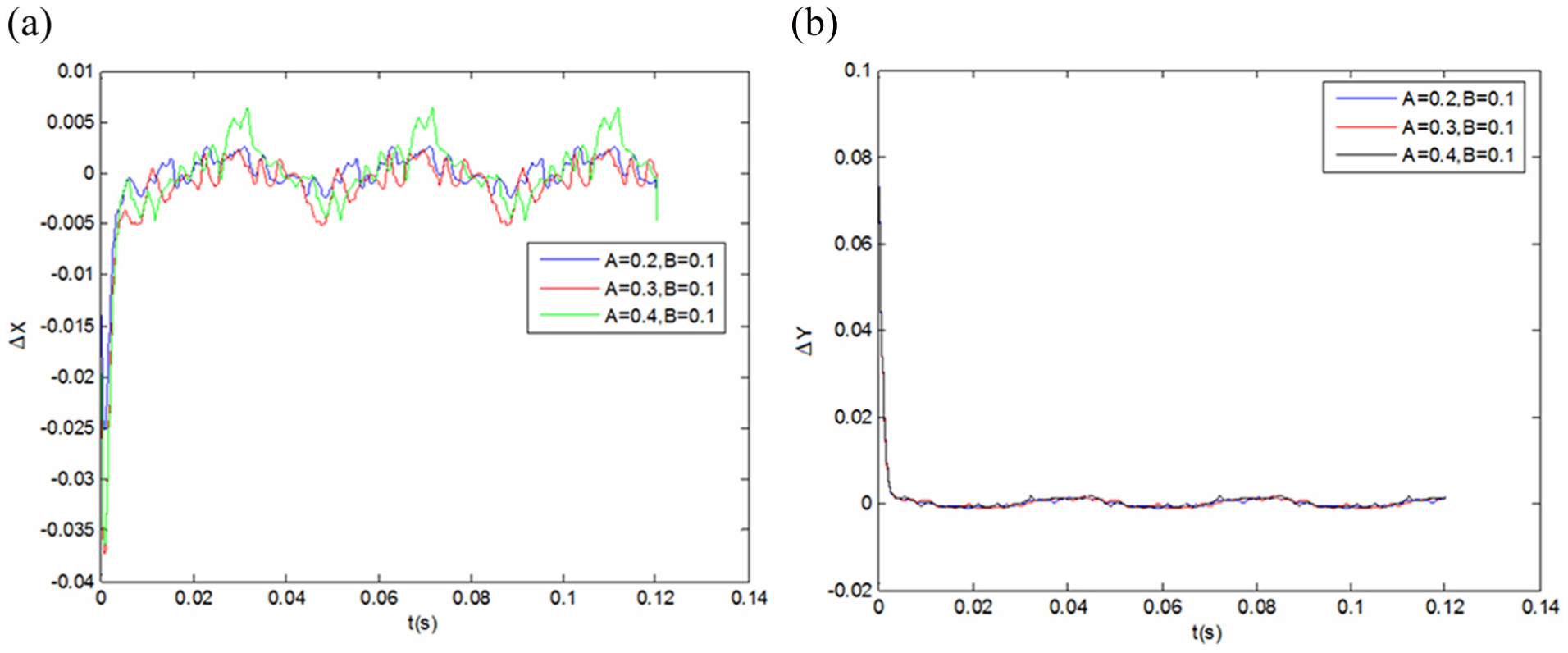
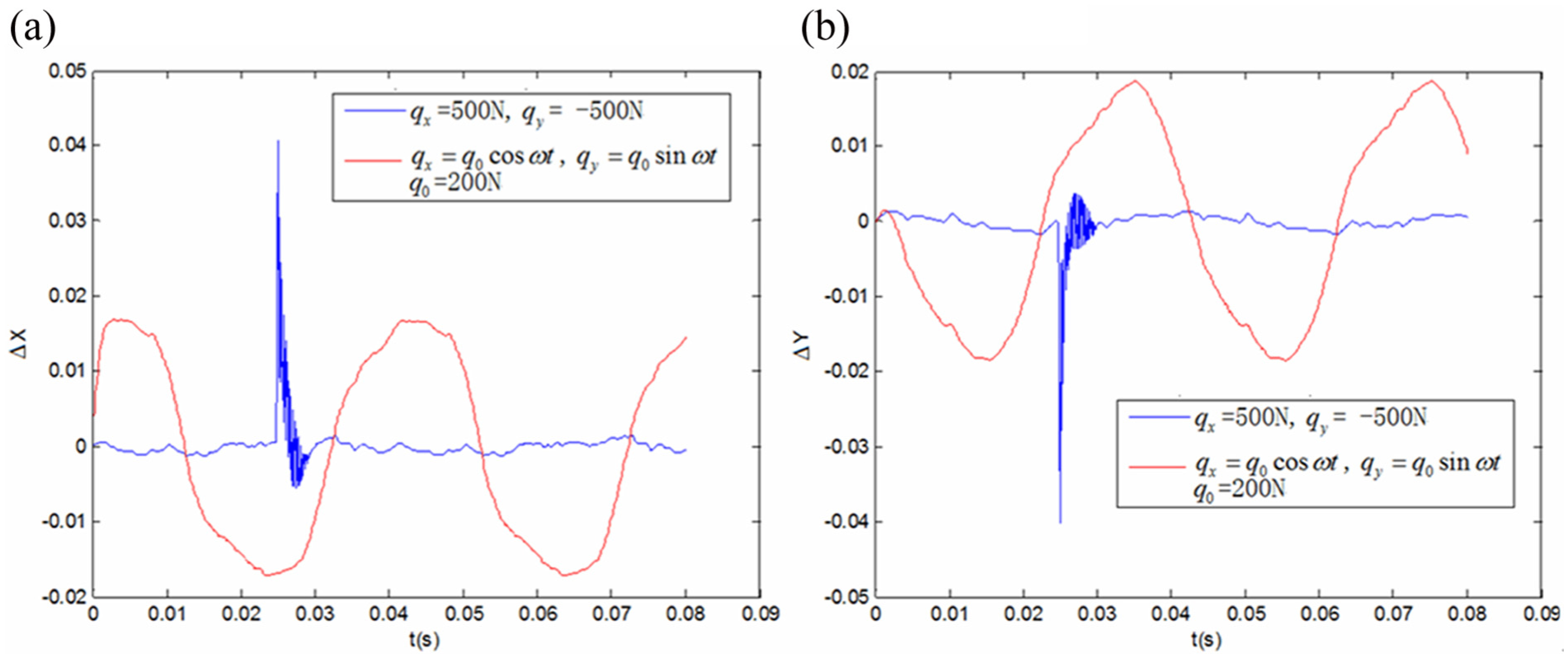
(a) Tracking errors of shaft center coordinates in X-direction under different ovalities and (b) tracking errors of shaft center coordinates in Y-direction under different ovalities.
(a) Tracking errors of shaft center coordinates in X-direction under different disturbing forces and (b) tracking errors of shaft center coordinates in Y-direction under different disturbing forces.
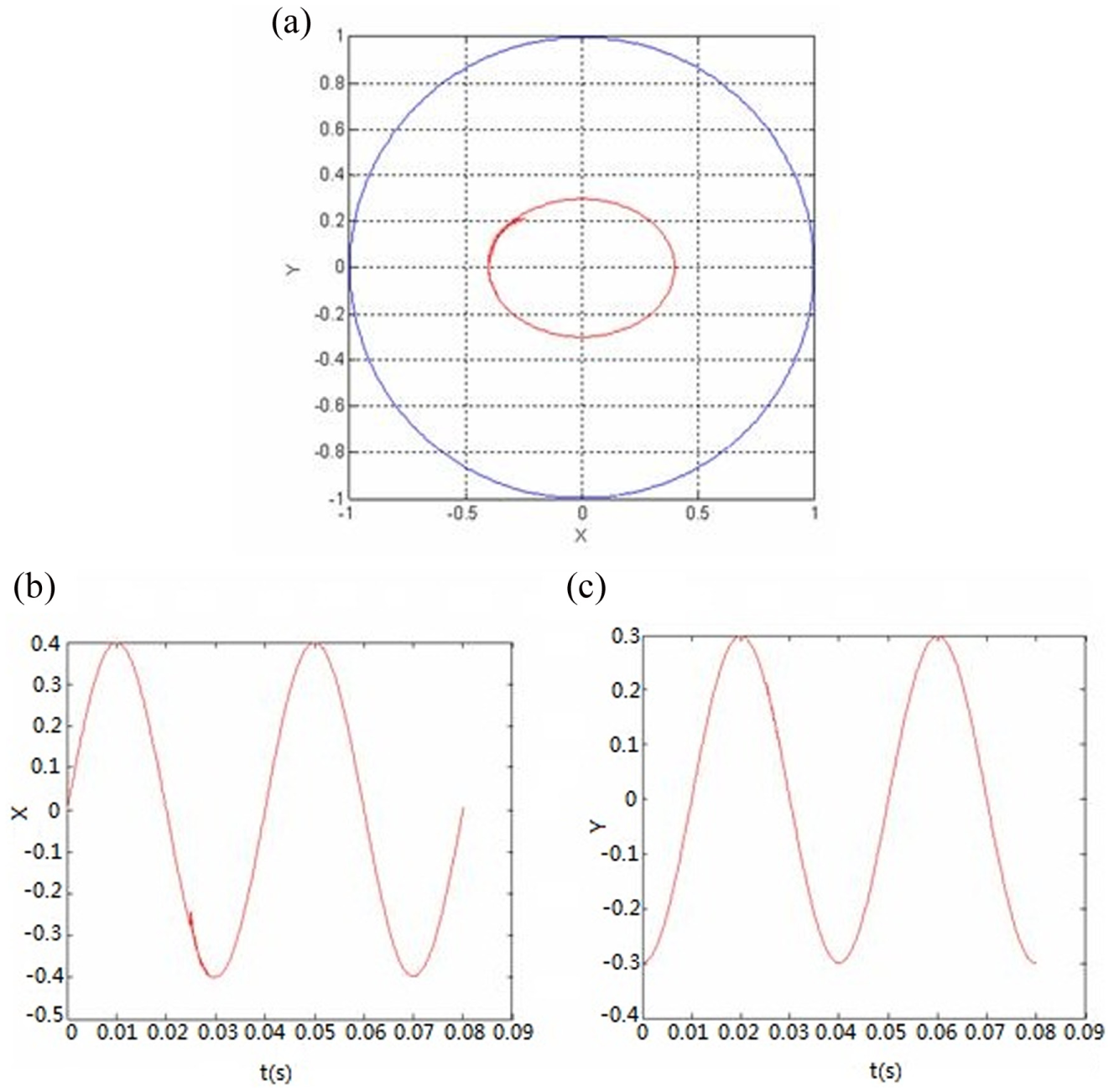
The shaft is often disturbed by instantaneous external force in moving process, so this article makes open-loop control simulations under that situation. Figures 11–13 are the open-loop control orbits of shaft center under the condition of instantaneous external disturbing forces. In the three figures, the non-dimensional semi-major axis length A of ellipse formed by shaft center movement orbit is 0.4 and semi-minor axis length B is 0.3. The non-dimensional initial coordinates of shaft center are (0, −0.3), and the initial velocities are (0, 0). Figure 11 is the open-loop control movement orbit of shaft center when the shaft is disturbed by an instantaneous external force (qx = 500 N) in the X-axis direction. It can be seen that shaft center has small vibration in the X-axis direction, but shaft center will quickly approach the expected ellipse, which indicates the good anti-interference of open-loop control method. Figure 12 is the open-loop control movement orbit of shaft center when the shaft is disturbed by an instantaneous external force (qy = −500 N) in the Y-axis direction. It can also be seen that shaft center has small vibration in the Y-axis direction, but shaft center will quickly approach the expected ellipse. Figure 13 is the open-loop control movement orbit of shaft center when the shaft suffers from two instantaneous external forces (qx = 500 N, qy = −500 N) in the direction of X- and Y-axes. It can be seen that shaft center has small vibration both in the direction of X- and Y-axes, but shaft center will quickly approach the expected ellipse. Figures 11–13 indicate that open-loop control method has good controlling effect and robustness for instantaneous external disturbing force.
When the shaft rotates inside the bearing, it may be disturbed by dynamical force whose value and direction vary with time. In this article, the sine dynamic load and cosine dynamic load are chosen as examples for dynamical disturbance force. Figure 14 is the open-loop control simulations of shaft center movement orbit when the shaft is disturbed by dynamical disturbance forces (
Figure 15 indicates the tracking errors of the shaft center coordinates under different ovalities. Figure 15(a) and (b) shows the tracking errors in the X- and Y-directions, respectively. It can be seen from Figure 15 that the tracking errors of initial stage are big, because the initial point of shaft center is on the original point instead of the expected ellipse (it can be seen in Figures 8–10). But after the adjustment for short time, the tracking errors in the X- and Y-directions become small and the tracking precisions become high. As can be seen in Figure 15(a), the variation range of tracking errors in the X-direction becomes wider as the value of A increases, that is, the variation range becomes wider when the length of the expected ellipse’s semi-major axis increases. When A = 0.4, the range of the tracking errors in the X-direction is widest, the biggest tracking error in steady state is 0.006421, and the percentage error is 1.61%. When A = 0.2, the range of the tracking errors in the X-direction is narrowest, the biggest tracking error in steady state is 0.00264, and the corresponding percentage error is 1.32%. It can be seen from Figure 15(b) that the tracking error in the Y-direction is also small.
Figure 16 shows the tracking errors of the shaft center coordinates under different disturbing forces. In the figure, the blue curve indicates the tracking errors under the condition of instantaneous external disturbing forces (qx = 500 N, qy = −500 N) and the red curve indicates the tracking errors under the condition of dynamical forces (
Conclusion
On the basis of previous work,13,21,22 this article simulates open-loop control movement orbits of shaft center using Eulerian method. With open-loop control method, this research can control shaft center movement orbit and make it an expected ellipse. The above work lays theoretical foundation for machining elliptical holes. Several conclusions can be gained by summarizing the above work:
A new hydrostatic bearing (i.e. pocket-nest hydrostatic bearing) is proposed. Comparing with the pocket of common hydrostatic bearing, control pocket of pocket-nest hydrostatic bearing has smaller area and flow. So control sensitivity of hydraulic control system can be enhanced with this new hydrostatic bearing.
When the hydrodynamic effect of bearing land is ignored, oil film pressure of bearing land can be linearizingly valued. Analytical expressions of pocket pressure and bearing load capacity are deduced. The method of using analytical expressions to solve pocket pressure and bearing load capacity is very simple.
Open-loop control method can control shaft movement and make the shaft center movement orbits’ expected ellipses with different ovalities. Even if the initial coordinates of shaft center are not on the expected ellipse, open-loop control method can make the shaft center close to the expected ellipse.
Open-loop control method is of high anti-interference. The simulation results indicate that when the shaft center is disturbed by instantaneous external force or dynamic load during the moving process, open-loop control method has strong robustness against those disturbance forces and make the shaft center quickly approach the expected ellipse.
Footnotes
Appendix 1
Declaration of conflicting interests
The author(s) declared no potential conflicts of interest with respect to the research, authorship, and/or publication of this article.
Funding
The author(s) disclosed receipt of the following financial support for the research, authorship, and/or publication of this article: This research was supported by National Natural Science Foundation of China (Nos 51505245, 51375275, 51205219, 51305242).