
Abstract
It is essential to determine the micro-machinability performance of polymer and glass fiber–reinforced polymer composite in order to effectively utilize the polymer and its composite as an engineering material at the micro-scale world. However, a literature survey revealed that not much work was done on the micro-milling of polymer and its composite. In the light of literature surveys, it can be said that the novelty of this study is to investigate the micro-milling performance of polypropylene and glass fiber–reinforced polypropylene manufactured with plastic injection molding process. The tests were performed at different feed rates and spindle speeds and the effect of these parameters on tool wear, burr width and micro-milling forces was investigated. In general, it was concluded that wear and forces in micro-milling of reinforced polypropylene composite were higher than that of unreinforced polypropylene. Micro-milling forces increased with feed rate and spindle speed for both materials. The lowest top burr size and force values were obtained at the feed of 50 mm/min and the spindle speed of 20,000 r/min. Unreinforced polypropylene gave better performance with respect to glass fiber–reinforced polypropylene composite from micro-machinability aspect.
Introduction
Nowadays, polymeric materials have been widely employed in various industries due to good thermal, mechanical and physical properties of these materials. 1 Although these materials can be manufactured as near net shapes,2,3 excess polymeric material is cut with the aid of machining process to meet assembly 3 and dimensional requirements. 4 Moreover, machining may be more economic than other processes such as molding when lower manufacturing numbers are needed. 5 Owing to these facts, there is a demand to determine the machinability characteristic of polymeric materials.6,7
Glass fiber is widely incorporated to polymeric materials for enhancing the strength of polymers. 8 Glass fiber–reinforced polymers are widely utilized for engineering industries from aircraft to automotive components due to some pros such as high fracture toughness, high strength to weight ratio and excellent thermal and corrosion resistance when compared to other conventional (traditional) materials.9–11 However, the machining of glass fiber composite is a very complicated task, 12 especially milling is a rather complex job due to the heterogeneity of composite materials.13–15 The operators have faced some hardships when machining of fiber reinforced polymers because information acquired for traditional materials cannot be applied to plastic materials. 16 It is also known that nonhomogeneous and anisotropic properties of these materials make the machining process different from traditional materials.17–19
Although the machinability of polymeric materials has been the topic of some works during drilling,20–26 turning27–29 and milling1,30–35 processes, there has been little study on micro-machining36–39 process up till now. Drilling performance of glass fiber–reinforced polypropylene (PP) and polyester was investigated with respect to torque, thrust force, surface roughness, chip morphology and tool wear. 20 Palanikumar et al. 21 determined the influence of machining conditions (spindle speed, drill diameter and feed rate) on thrust force in drilling of glass fiber–reinforced PP. Rubio et al. 22 evaluated the influence of feed, spindle speed and tool geometry on circularity error, hole diameter and force during drilling of polyamide (PA) 6 and 30% of glass fiber–reinforced PA6. The effect of feed and cutting speed on specific cutting pressure, force and power in turning of PA and 30% of glass fiber–reinforced PA was evaluated by Gaitonde et al. 27 In another study, these researchers determined the optimum parameters (tool material, cutting speed and feed rate) for simultaneously minimizing the power and specific cutting force in turning of PA and 30% of glass fiber–reinforced PA. 28 The effect of feed and cutting speed on power, surface roughness and specific cutting pressure was investigated in turning of polyetheretherketone (PEEK) and 30% of glass fiber–reinforced PEEK. 29 The effect of feed, spindle speed and nano calcium carbonate content on the machinability performance of PA was investigated during milling. 1 Machinability of carbon fiber reinforced epoxy was determined with respect to chip characteristics, burr, surface roughness and force during milling. 30 Dhokia et al. 31 established surface roughness prediction model during milling of PP. Milling performance of glass fiber–reinforced polymer was conducted by the researchers and surface quality, tool life and forces were employed to determine the machinability of this composite.32,33 Azmi et al. 34 developed wear prediction model in milling of glass fiber–reinforced composites. The optimum spindle speed, feed and depth of cut was determined during milling of glass fiber–reinforced plastic composite to minimize delamination factor and surface roughness. 35 Works on micro-machining of polymeric materials are lower with respect to the macro-machining. Micro-drilling of polyacetal and polyetherimide was conducted by Endo and Marui. 36 Davim et al. 37 evaluated the machinability performance of PA with and without 30% glass fiber reinforcement during micro-turning at various tool materials and feed rates. Chen et al. 38 determined the influence of feed rate, spindle speed, coolant and depth of cut on the quality of surface in micro-milling of polymethyl methacrylate (PMMA). Surface roughness in micro-milling of PMMA was investigated by Jiao and Cheng. 39
In recent years, the miniaturization of the parts makes the micro-machining process such as micro-milling very significant in the machining field. Micro-milling has been widely employed to manufacture polymer microfluidic devices. Faster manufacturing, lower cost and being capable of fabricating complex structures make micro-milling process a good candidate in the manufacturing of polymer microfluidic devices for research and industry. 38 However, literature surveys revealed that not much work was carried out on the micro-milling of polymer and polymer composites, and no work was performed on the micro-milling of PP polymer and glass fiber–reinforced PP composite to the best of author’s knowledge. Understanding of micro-milling characteristic of polymer and glass fiber–reinforced polymer composite is important to efficiently utilize the polymeric materials as a material at micro-scale industry. In order to reach this aim, in this work, the micro-milling of PP and glass fiber–reinforced PP produced by plastic injection molding were determined. Tool wear, micro-milling forces and burr occurrence in micro-milling of these polymeric materials were determined. The tests were performed at various feed rates and spindle speeds and the effects of these micro-milling conditions on forces, tool wear and burr width were evaluated. Consequently, this study attempted to fill the gap on the micro-milling of PP and glass fiber–reinforced PP composite by investigating the effect of spindle speed and feed rate on the tool wear, forces and top burr formation. Thus, the micro-machinability performances of PP polymer and glass fiber–reinforced PP composite were determined with the aid of this study.
Materials and methods
In this work, PP (Petkim Petoplen MH 418) and 30% of glass fiber–reinforced PP (Tosaf GF1436HP) were selected as workpiece materials. Throughout this study, 30% of glass fiber–reinforced PP was coded as PP-GF. Experimental stages employed in this work were as follows: drying of polymeric granules, plastic injection molding process, cutting workpiece from molded samples at desired dimensions and micro-milling process. Prior to molding, polymeric materials were dried to minimize air bubbles. After drying, granules were injection molded at a shape of dog bone (Figure 1) in accordance with ISO 527 40 at the conditions presented in Table 1 by employing an injection molding machine (YIZUMI-UN90A2). The tensile properties were evaluated using Instron 5569 machine and results of average for five tests are depicted in Figure 2. After that the specimens were cut into from the injection-molded samples at the desired dimensions employing a saw. Stage of producing the micro-milling samples is given in Figure 3. The dimensions of cut sample were 32 mm × 4 mm × 20 mm. Micro-milling tests of the molded PP and PP-GF were conducted on DECKEL MAHO DMU 60 P CNC which reaches a maximum of 12,000 r/min. The machine tool was fitted out with a high speed spindle attachment (Pibomulti X9810) which can rotate a maximum spindle speed of 40,000 r/min. In the experiments, 400 µm diameter, two-flute flat micro end mill (CES3A20040-015, Union Tool) was employed. The micro end mill was coated with TiAlN and helix angle was 20°. In each test, a brand new micro tool was utilized. The overhang length of tools was held constant as 13.4 mm during all tests. Prior to micro-milling tests, the static runout of end mill was measured with dial gauge at the shaft part of micro end mill. The static runout was measured to be below 4 µm for all tests. All tests were done at dry environment and micro-milling conditions are presented in Table 2. For each material, six tests were carried out at the various micro-milling conditions given in Table 2. In each test, slot was micro-milled at the dimensions in Figure 4.
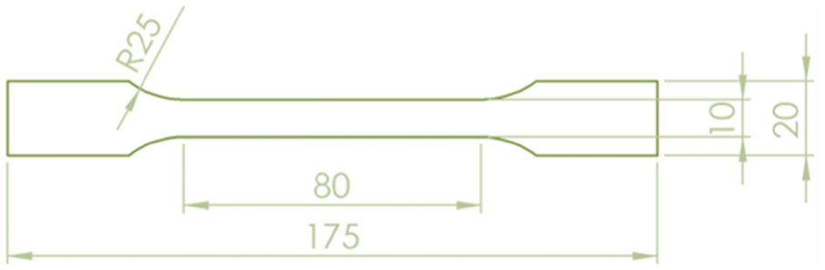
Dimensions of injection-molded sample (ISO 527).
Injection molding conditions for PP and PP-GF.
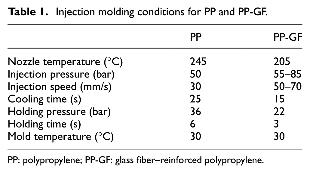
PP: polypropylene; PP-GF: glass fiber–reinforced polypropylene.
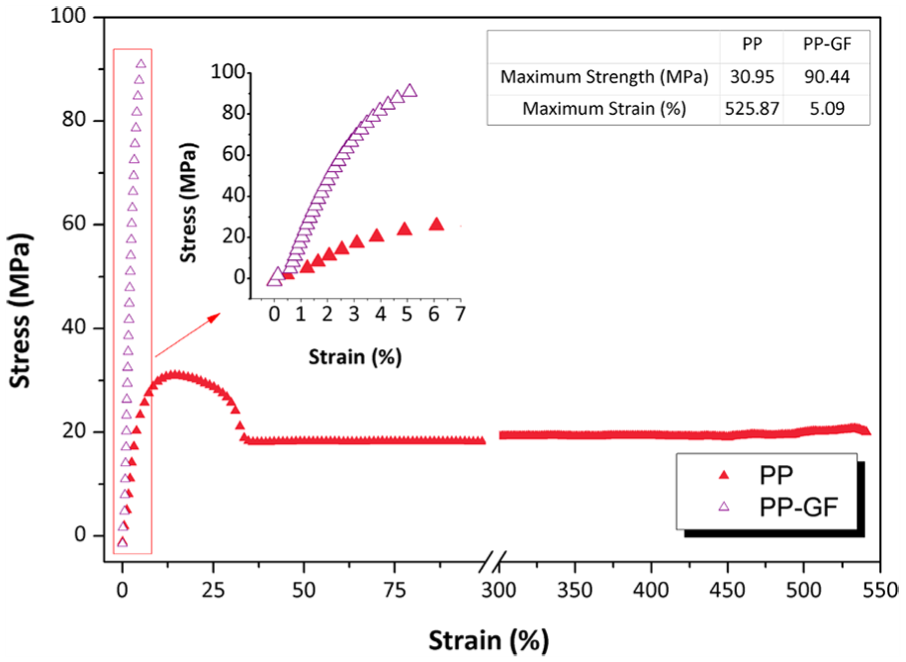
Results for tensile properties of injection-molded PP and PP-GF.
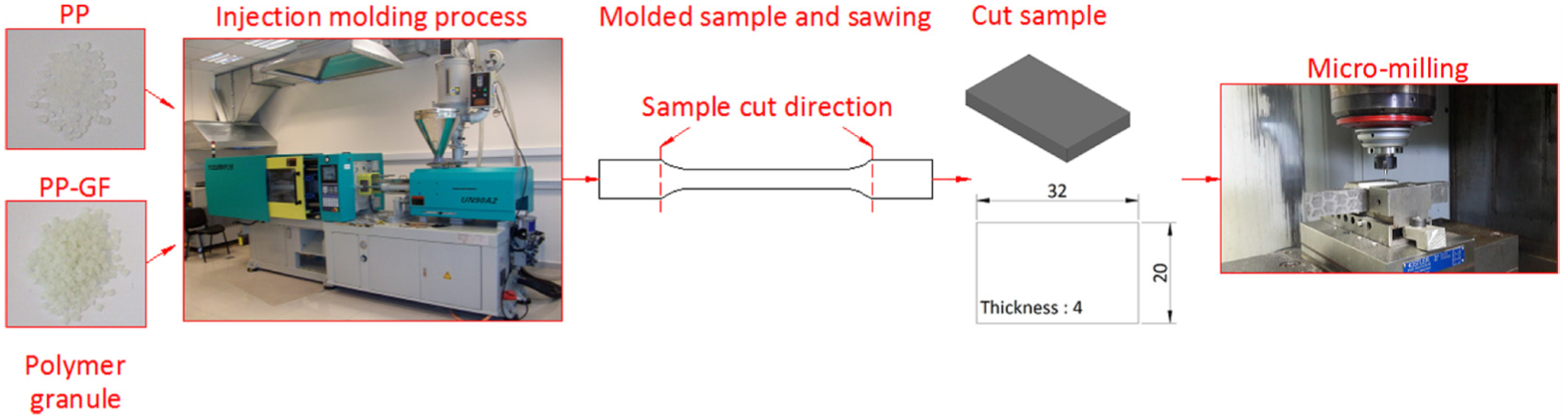
Experimental procedures (all units are in mm).
Micro-milling conditions for PP and PP-GF.
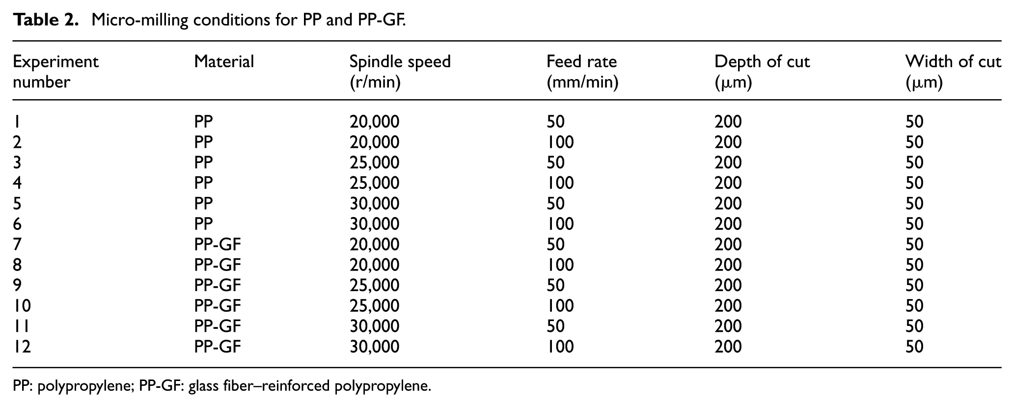
PP: polypropylene; PP-GF: glass fiber–reinforced polypropylene.
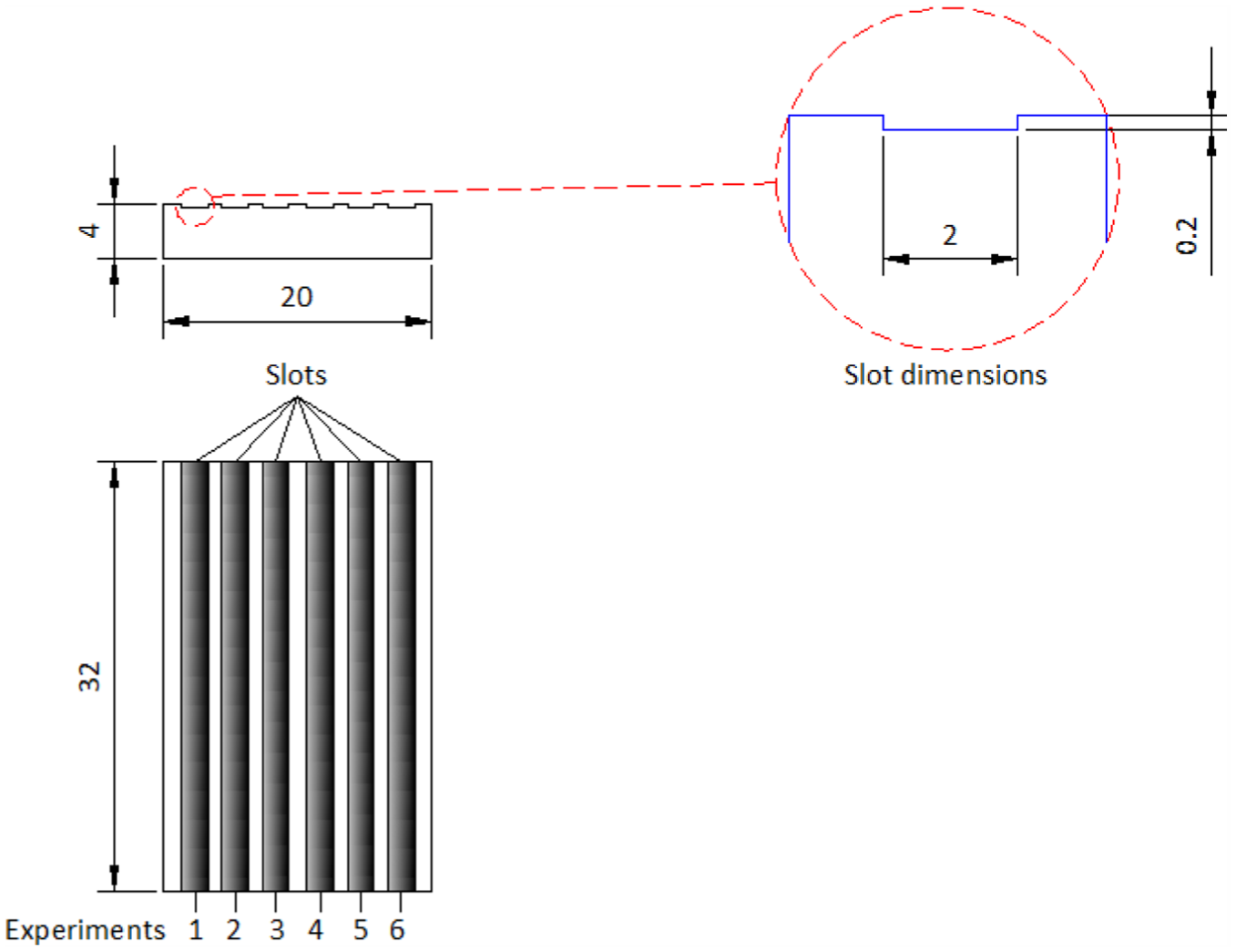
Dimensions of micro-milled slots (all units are in mm).
In this work, wear, micro-milling forces and burr occurrence in micro-milling of PP and PP-GF were examined. Scanning electron microscope (SEM, Philips XL30) was used to determine tool wear. Forces were measured online via a table type dynamometer. Burr was evaluated via SEM and top burr width was considered for up and down micro-milling. Prior to SEM observation, PP and PP-GF specimens were gold coated with a 30 nm layer by employing Quorum SC7620 sputter coater.
Results and discussion
Tool wear
SEM micrographs of end mills employed during micro-milling of PP polymer are depicted in Figure 5. It was seen that both cutting edges of the micro end mills gave different wear values, which could be the evidence of different chip load of cutting edges. Chip adhesion on flank face was seen after micro-milling of PP. However, no clear relationship between micro-milling conditions (feed rate and spindle speed) and adhesion was seen when experiment was carried out with PP polymer. After micro-milling of unreinforced PP polymer, flank wear, chipping and fracture were also seen at used micro end mills. In general, it was observed that wear values increased with spindle speed and feed rate after micro-milling of PP polymer. The feed rate of 50 mm/min and the spindle speed of 25,000 r/min resulted in the lowest wear value.
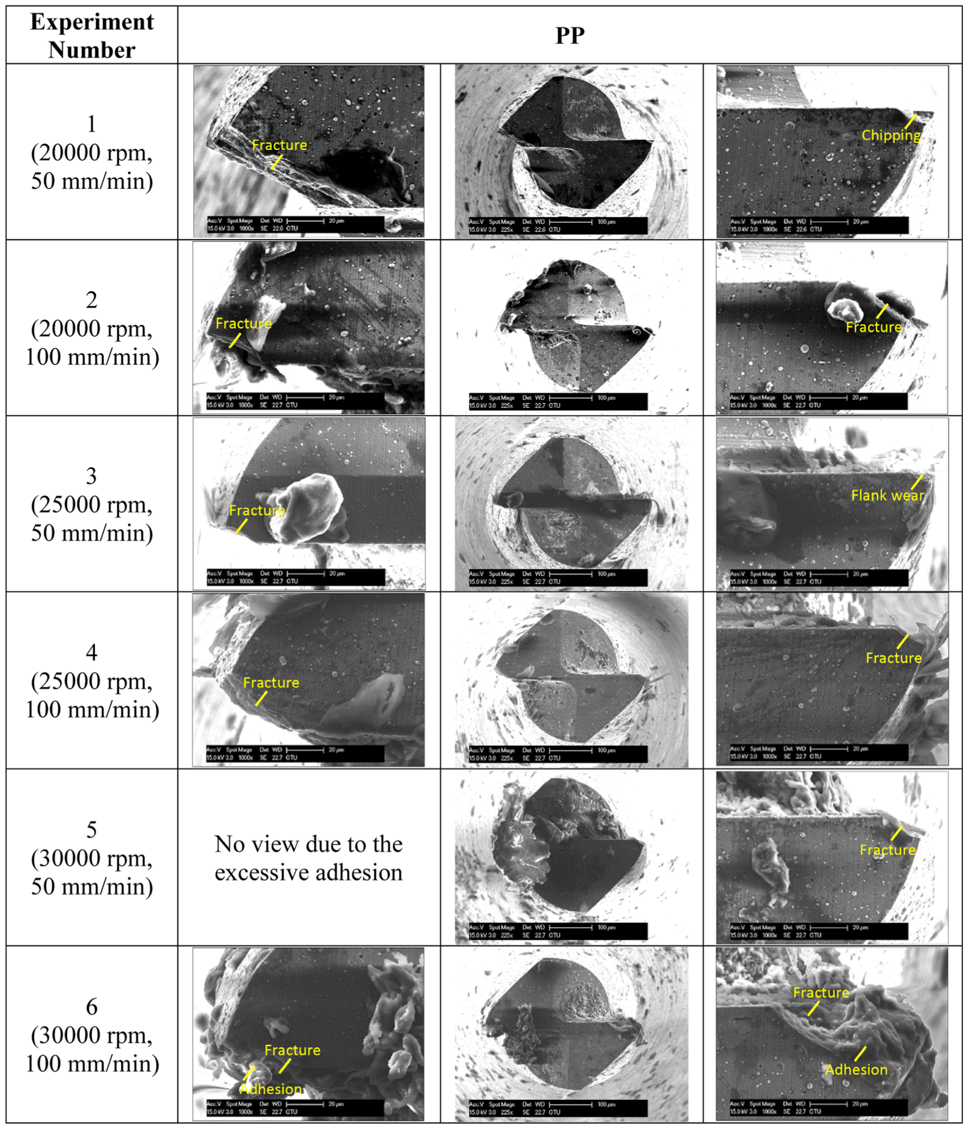
SEM micrographs of micro end mills used for PP material.
SEM micrographs of micro end mills employed during micro-milling of PP-GF composite are given in Figure 6. In general, it was observed that wear values increased with spindle speed and feed rate after micro-milling of PP-GF composite. This result was consistent with the study conducted by Palanikumar and Davim 10 during machining of glass fiber–reinforced polymer composite. These researchers stated that the increment in the feed rate resulted in heat generation between cutting tool and workpiece material which gave higher tool wear value. 10 The lowest wear value was obtained at the feed rate of 50 mm/min and the spindle speed of 20,000 r/min. After micro-milling of reinforced PP composite, flank wear, chipping and fracture were observed at used micro end mills. Micro-milling was an intermittent process and this nature of its induced in high changing at the forces, which resulted in the formation of chipping on the micro end mill. The formation of chipping was also owing to the cyclic stresses of intermittent machining in milling process when the end mill encountered different phases (fiber and matrix) of glass fiber–reinforced polymer composite. 33 These researchers explained that the combination of shearing and bending rupture with little plastic deformation was major mechanism of cutting for fiber-reinforced polymer composites and chipping generally formed during machining of these composites due to this chip formation mechanism. 33 In general, it was seen that tool wear in PP-GF composite was higher than that in PP polymer. The mechanical resistance owing to the existence of glass fiber induced increase in wear. 21 It was stated that wear for fiber-reinforced polymer composites was due to the abrasive behavior of glass fiber. 41
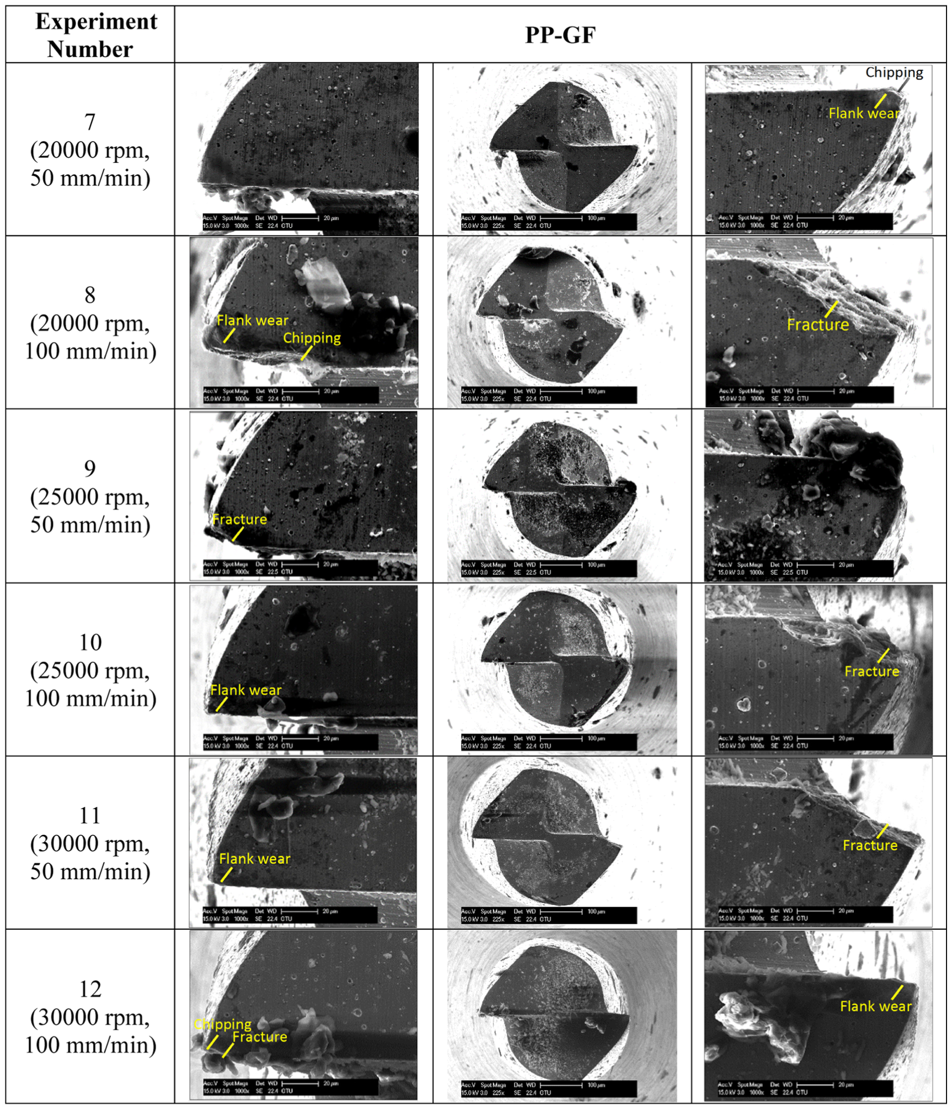
SEM micrographs of micro end mills used for PP-GF material.
Forces
Stages of force analysis in this study are given below:
Drift at the non-cutting stage was eliminated. In order to remove the drift, mean value of forces in non-cutting stage was computed for at the starting and at the ending of the experiment. After that mean of two values was saved for eliminating the drift.
By employing a low-pass filter, the measured forces were filtered.
The maximum peak-to-valley (P-to-V) force was estimated and results of Fx and Fy are depicted in Figure 7.
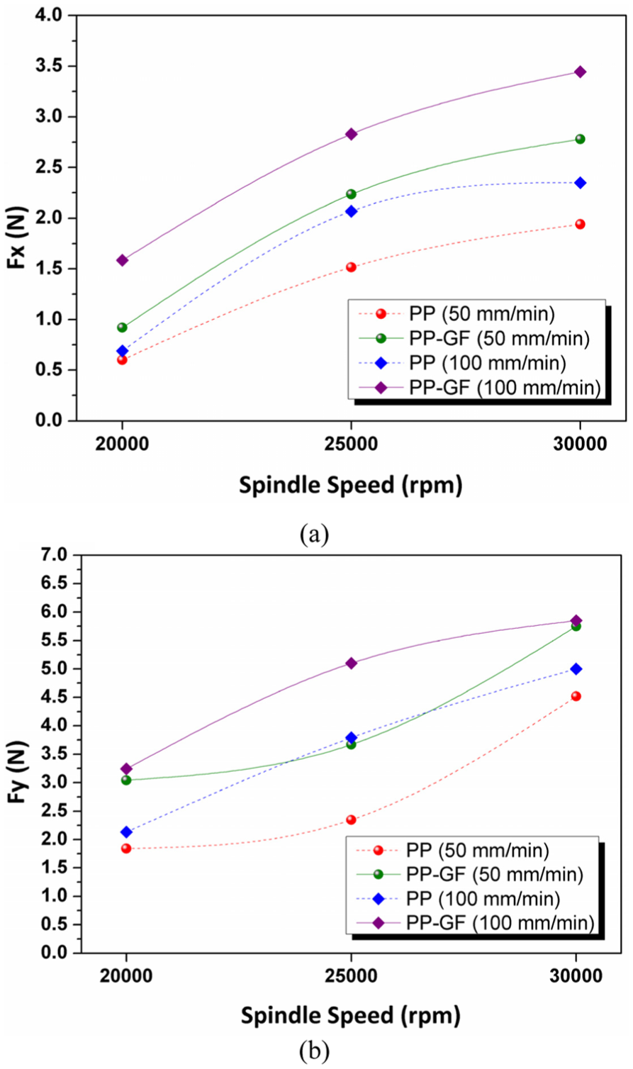
(a) P-to-V Fx and (b) P-to-V Fy force values as a function of spindle speeds and feed rates.
Maximum P-to-V Fx was in the range of 0.60–2.35 N for PP polymer and in the range of 0.920–3.445 N for PP-GF composite. Maximum P-to-V Fy values were in the range of 1.84–5.00 N for PP polymer and in the range of 3.04–5.85 N for PP-GF composite. The feed rate of 50 mm/min and the spindle speed of 20,000 r/min resulted in the lowest P-to-V Fx and Fy values for unreinforced and reinforced PP. It was concluded that maximum P-to-V Fx and Fy values increased with increasing feed rate at all spindle speeds for PP and PP-GF materials. Increment in the force values with feed rate was owing to the increment in the contact area among the tool and workpiece.27,42 Maximum P-to-V Fx and Fy values increased with the increase in spindle speed at all feed rates for PP and PP-GF materials. The increase in spindle speed induced increase in the strain hardening of workpiece, thus the deformation resistance of shear area increased, which induced increment in the force. 43 The increment in the cutting force with spindle speed was also declared44,45 by the increment friction between the micro end mill and workpiece with spindle speed. 44 The increase in the forces with spindle speed and feed rate was also reported in the literature studying micro-milling of unreinforced and glass fiber–reinforced polymer composite. 6 In general, maximum P-to-V Fx and Fy values were higher for PP-GF composite than those for PP polymer. This was the evidence that the micro-milling of PP polymer was easier than that of PP-GF composite and PP polymer needed lower energy as compared to PP-GF composite during micro-milling. Higher force of reinforced PP composite with respect to unreinforced PP polymer was due to the fracture of glass fiber during micro-milling. It was stated that repeated bending occurred during micro-milling of reinforced composite could induce in higher forces. Glass fiber in front of the micro end mill bent at the tool direction when micro end mill cut the glass fiber–reinforced composite. As a result of this fact the forces recorded during micro-milling of reinforced PP composite were higher than that of unreinforced PP polymer. In the literature, similar result was found during machining of unreinforced and reinforced polymeric materials. Gaitonde et al. 27 reported that forces in machining of 30% glass fiber–reinforced PA66 were higher with respect to unreinforced PA6. The increment in the force was explained with the effect of glass fiber reinforcement. 3 Davim and Mata 46 found that glass fiber–reinforced PA gave higher forces than unreinforced PA. Davim et al. 47 stated that the machinability of glass fiber–reinforced PEEK composite was poor as compared to unreinforced PEEK due to the higher forces.
Burr formation
SEM views of burr occurrence after micro-milling of PP polymer are presented in Figure 8 for both up and down micro-milling. Quantitative analysis of top burr was very difficult due to the wavy nature of top burr; therefore, qualitative analysis was done in this study. Top burr at down micro-milling side in PP polymer was found to be very high as compared to up micro-milling side. In up micro-milling, the undeformed chip thickness was zero at the starting of milling and then increased, which supported the cutting process in a shearing mode. Conversely, in down micro-milling, the chip thickness decreased at the last phase of milling process and under this circumstance the workpiece was not clearly cut. 48 This was the reason why top burr size at down side of the micro-slot was bigger than that at up side. Bigger burr size in down milling side as compared to up milling side was also found by previous researchers.6,49,50 It could be seen from Figure 8 that there was a positive relation among micro-milling parameters and burr size at down micro-milling side for PP polymer. The increment in both feed rate and spindle speed resulted in the increase in top burr size. Similar result was also seen at up micro-milling side. The increase in the burr size with spindle speed 48 and feed rate48,49 was reported by previous researchers studying micro-milling. Biermann and Steiner 48 explained the increment in the burr size with increasing spindle speed by the strain rate hardening. These researchers stated that the materials’ resistance against plastic deformation increased at higher spindle speed. As a result, the material was squeezed to a greater extent during the machining process and then pushed to the top of the slot, producing higher burr size. The material removal rate increased when feed per tooth was increased. At this condition, more material had to be removed from the cutting area, thus chip removing was slowed down and as a result more material was squeezed at the top of the slot, which increased the top burr size. 48 The lowest top burr size was obtained at the feed rate of 50 mm/min and the spindle speed of 20,000 r/min.
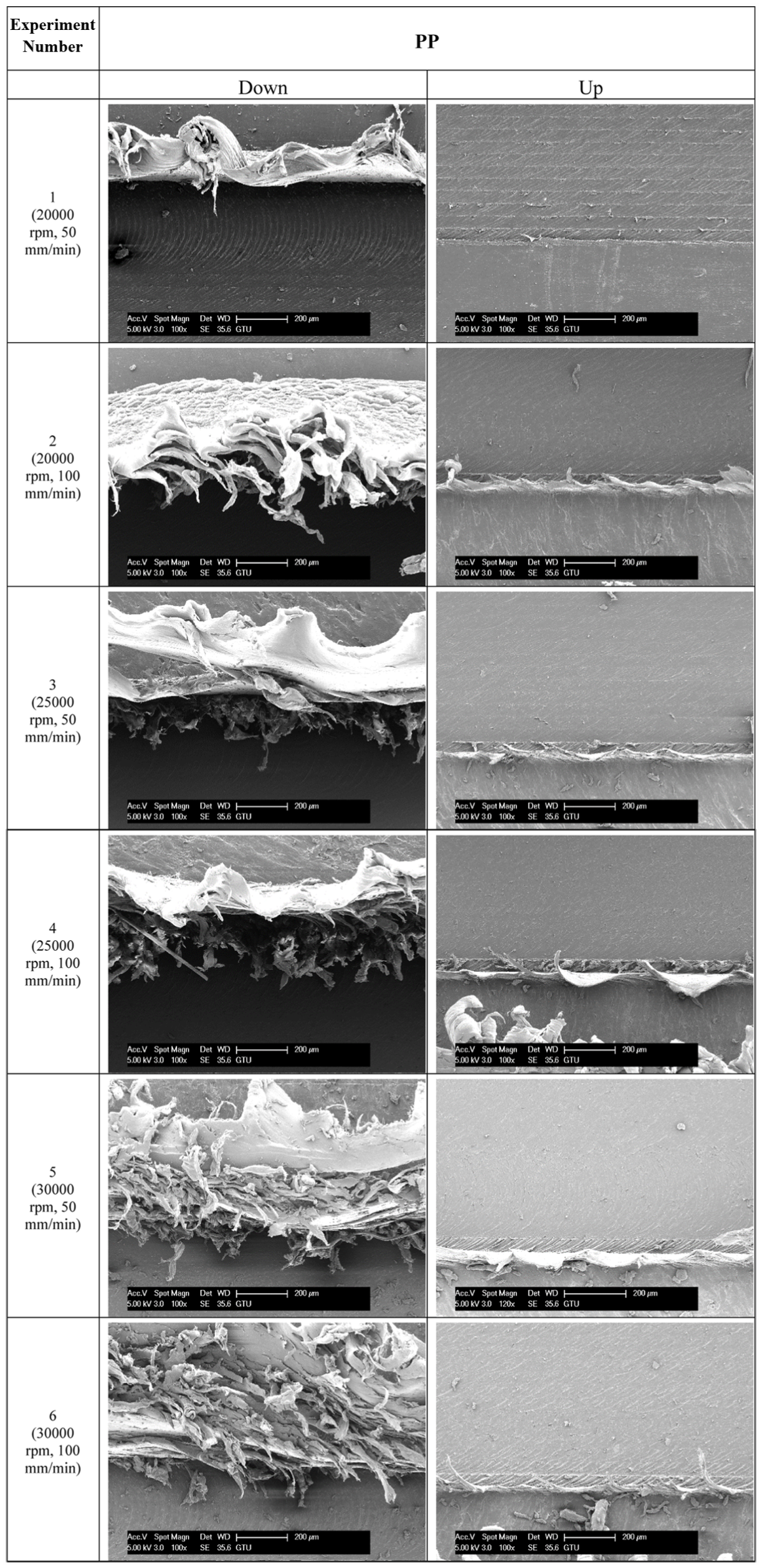
SEM micrographs of top burr for PP material.
Wall type burr was observed at both down and up side during micro-milling of PP polymer. At wall type burr, workpiece material formed a continuous material with no cracks and discontinuities. 51 The tearing of material in front of the cutting tool resulted in wall type burr. Owing to the bending of burr, wall type burr roll over, especially at down side of the slot. It was explained that rollover burr was the attached chip to workpiece and was pushed by micro end mill on exit from the workpiece. 52 The burr mechanism observed in this study was similar to the burr mechanism in the micro-milling seen in the literature. 6
SEM views of burr occurrence for PP-GF composite are presented in Figure 9 for both up and down micro-milling. As observed during micro-milling of PP, it was seen that top burr of down side was bigger than up side for PP-GF composite. It was seen in this figure that there was no obvious relationship among spindle speed, feed rate and burr size. However, it could be concluded that the lowest top burr size was obtained at the feed rate of 50 mm/min and the spindle speed of 20,000 r/min.
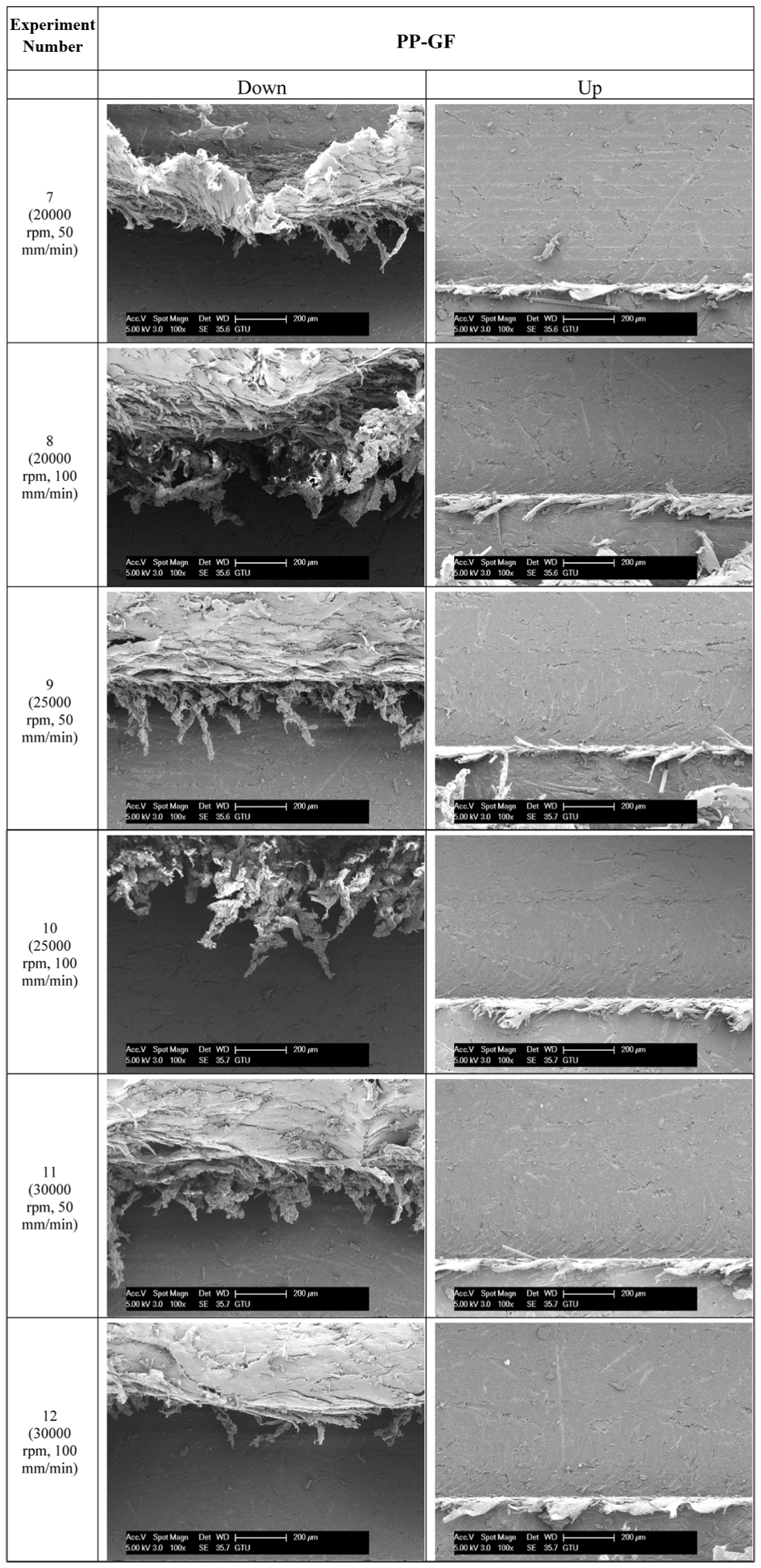
SEM micrographs of top burr for PP-GF material.
The surface of micro-slot floor was also examined with the aid of Figures 8 and 9. After micro-milling of PP polymer at the feed rate of 50 mm/min and spindle speed of 20,000 r/min, the step over traces on the surface could be seen. Micro-burr on the surface of slot floor was also observed. Friction between the micro tool and PP polymer resulted in heat generation at the contact area, which softened the polymeric matrix. As a result, micro-burr occurred on the slot surface, which diminished quality of surface.6,53
After micro-milling of PP-GF composite at the feed rate of 50 mm/min and spindle speed of 20,000 r/min, the step over traces on the surface could be seen. For all conditions, protrusion/pullout of glass fiber from micro-milled surface resulted in the void on the slot surface, which deteriorated quality of surface.
Conclusion
In current experimental work, the micro-milling characteristic of PP and glass fiber–reinforced PP produced via plastic injection molding process was determined. Tool wear, forces and top burr in micro-milling of unreinforced and reinforced PP were investigated. The tests were done at different feed rates and spindle speeds. Results demonstrated that tool wear and forces in micro-milling of reinforced PP composite were higher than those of unreinforced PP polymer. Adhesion on the micro end mill, flank wear, chipping and fracture were observed for unreinforced PP; however, flank wear, chipping and fracture were observed for glass fiber–reinforced PP. Maximum P-to-V Fx was found to be in the range of 0.60–2.35 N for PP polymer and in the range of 0.920–3.445 N for PP-GF composite. Maximum P-to-V Fy was found to be in the range of 1.84–5.00 N for PP polymer and in the range of 3.04–5.85 N for PP-GF composite. It was concluded that maximum P-to-V Fx and Fy values increased with increasing feed rates and spindle speeds for both PP and PP-GF materials. In general, maximum P-to-V Fx and Fy values were found to be higher during micro-milling of PP-GF composite than that during micro-milling of PP polymer. This result was the evidence that the micro-milling of PP was easier than that of PP-GF, and micro-milling of PP required lower energy as compared to PP-GF. After micro-milling of reinforced PP composite, voids on the machined surface were observed due to the pullout of fibers during the micro-milling process. Top burr obtained with down micro-milling was bigger than that with up micro-milling for unreinforced and reinforced PP materials. The increment in both feed rate and spindle speed resulted in the increase in top burr size for both down and up side in micro-milling of unreinforced PP and the lowest top burr size was obtained at the feed rate of 50 mm/min and the spindle speed of 20,000 r/min. There was no obvious relationship among spindle speed, feed rate and top burr size during micro-milling of reinforced PP; however, the lowest top burr size was found at the feed rate of 50 mm/min and the spindle speed of 20,000 r/min. During micro-milling of unreinforced and reinforced PP, the major burr shape was wall type burr for down and up side.
Consequently, the micro-milling performance of reinforced PP composite was poor with respect to unreinforced PP polymer. Although the reinforcement with glass fiber improved the thermal and mechanical properties of polymers, the reinforcement deteriorated the micro-machinability of polymers.
Footnotes
Acknowledgements
The author would like to thank Professor Babur Ozcelik for providing equipment employed in the experiments. The special acknowledgement goes to Onder Gedik and Hamit Ayvaz for their generous help in the experimental study and Ahmet Nazim for helping SEM analysis.
Declaration of conflicting interests
The author(s) declared no potential conflicts of interest with respect to the research, authorship and/or publication of this article.
Funding
The author(s) received no financial support for the research, authorship and/or publication of this article.