
Abstract
Miniaturization with superior quality product of super alloy is the demand of the industry. Ti6Al4V is the demanding super alloy due to its excellent material properties, although this super alloy is known for poor machinability in terms of burr formation, low tool life, and poor surface finish. Therefore, being a popular super alloy, it comes under the difficult-to-cut material. In the current work, burr formation on the machining of Ti6Al4V has been studied. Experimental investigation and characterizations of top burr formation on Ti6Al4V alloy using end milling process were carried out. A scanning electron microscopy identifies the burr formed on the machined surface. A new technique has been introduced to measure the top burr width (i.e. equivalent width) accurately. Equivalent burr width calculated as the ratio of total area of burr generated to the total height. It was observed that equivalent burr width in up milling was increased by 120%, while in down milling, it was decreased by 50% as the speed varies from conventional to high speed. Furthermore, the effects of different cutting parameters and tool parameters on top burr formation have been analyzed to establish correlation among them.
Introduction
Increasing use of the titanium and its alloys in engineering and biomedical field is primarily due to its superior mechanical properties, such as corrosion resistance, high strength of magnitude 620–1800 MPa, lightweight equivalent to 60% of engineering steel and good biocompatibility. However, its machining is very difficult. This has driven the need for some specific machining techniques to deal with the difficult-to-cut materials.1,2 Micro-milling proved to be an extensively used technique for fabricating miniature complex parts with high precision and accuracy.3,4 However, micro-machining of difficult-to-cut metals like Ti and Ni alloys has always been challenging, as low stiffness of micro-end tool makes it very prone to failure.5,6 High-speed micro-milling (HSMM) can be a way through which chip load and stiffness can be reduced, but at the same time, it creates chatter too. Previous researchers have investigated chatter instability and stability in micro-milling process using finite element modeling and numerical approach.7,8 Apart from chattering and damage to tool, burr formation is a big threat in HSMM of Ti64 alloys. Burr generation is a common problem arising in machining, but it is predominant when machining of difficult-to-cut metal alloys is done. This is due to generation of high temperature at high cutting speed. Various analytical studies have been done to analyze cutting temperature and force in machining.9–13 Burr reduces the fitting of components during assembly and disrupts part performance and accuracy. The HSMM of aluminum and titanium alloy leave the higher amount of burrs on the machined part as compared to conventional machining. Burr formation, their cause for occurrence and classifications (Poisson, rollover, tear, and cut-off burrs) in milling was first described by Gillespie and Blotter. 14 Furthermore, burr nomenclature based on their position in channel-milling operation was introduced by Hashimura et al., 15 and these are exit, side, and top burrs. Different types of top burr were formed, such as discontinuous, ragged, and longitudinal. The micro-end mill produced eight different types of burrs in a micro-channel operation as shown in Figure 1.
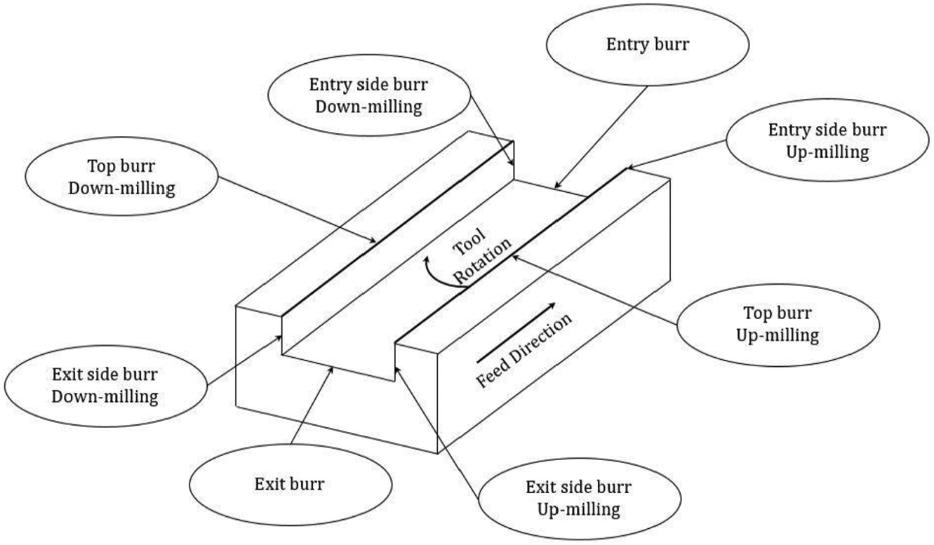
Types of burr generated in micro-channel milling.
It has been found that in micro-channel milling operation, the top burr formed at two different locations: the first kind of top burr was formed at the up-milling side and the second kind at the down-milling side. The formed burrs were difficult to remove in the micro-slot milling process. 16 Meanwhile, a three-dimensional (3D) finite element model was developed for the study of the top burr formation process. A 3D finite element simulation technique was utilized to show the result of tool roundness on burr formation in machining of Ti6Al4V. They observed that the tool nose radius directly affects the average burr height. 17 Minimum burr was found when the tool nose radius is equal to uncut chip thickness. 18 Experiments have been performed on the micro-milling machine to find the effect of machining time on burr formation of aluminum alloy 1100. 19 They observed that burr size increases with an increase in machining time because the tool got worn by increasing the machine time. Effect of tool geometry on the top burr formation of Al-6061 alloy in micro-milling using a carbide tool was investigated by Saptaji et al. 20 They found that an amalgamation of biggest taper and side cutting edge angle results in the tiny burr formation. Experiments were performed using multi-axis ball end milling with different tool angle inclinations to characterize the surface features. 21 In another study, they revealed that the micro-hardness and structure of the steel changed after the turning operation. 22 To predict burr size, cutting forces and friction angle simultaneously in slot milling of ductile materials, a computational model algorithm was proposed by Niknam and Songmene. 23 A mathematical model to predict the exit burr height was developed and validated successfully by experimental result in HSMM of Ti64 alloy. It was observed that the burr height decreases by 90% as the speed increases from 50,000 to 200,000 r/min. 24 Kizhakken and Mathew 25 developed a mathematical model to predict the burr thickness in micro-milling of Ti6Al4V alloy. They observed that hyperbolic tangent material model gives better prediction over Johnson–Cook material model. Removal of micro-burrs, especially the top burr, has been a challenging problem due to varying chip thickness, complex interactive effects among cutting parameters, and tool run-out. Efforts had been taken for elimination of burrs, however it was value-added, time-consuming, damaging close tolerances, and very expensive process.26,27 Effect of various parameters like cutting speed, feed rate, tool geometry, and the depth of cut on burr formation was analyzed for different work materials.28–30 Many researchers have successfully developed finite element 3D and two-dimensional (2D) models of chip and burr size on Ti64 alloy in HSMM to simulate experimental results.31–35 A new technique has been introduced to eliminate the top burrs, in which the epoxy resin was coated upon the top surface of Ti6Al4V before micro-end milling operation. 36 Vibration-assisted micro-milling setup based on piezoelectric plates was used to characterize the exit burr size. 37 The status and advancement of characterization, modeling, and control of burr formation have been reviewed. They summarized that the cutting parameters, workpiece mechanical properties, tool geometry, coating, and cutting fluids are such factors that affect the burr formation in micro-milling operations.38,39 In micro-milling of Ti64, the influence of different parameters on the formation of burrs and built up edge (BUE) has been studied. 40 They found that there is no connection among BUE and burr formation and large forces generated larger burrs. From the critical literature review, it is found that very less work has been done in the field of burr characterization and their minimization in the HSMM process of the Ti64 alloy. However, there is still a need to optimize cutting parameters using recent methods of optimizations 41 to machine burr-free surfaces. Therefore, this experimental work was done to estimate the effect of process and tool parameters in burr formation at HSMM of the Ti64 alloy.
Experimental work
A schematic flowchart of the experimental work has been shown in Figure 2. The experiments have been executed on the HSMM to investigate and characterize the top burr generation. Meanwhile, the consequence of process parameters upon the equivalent size of top burr has been studied.
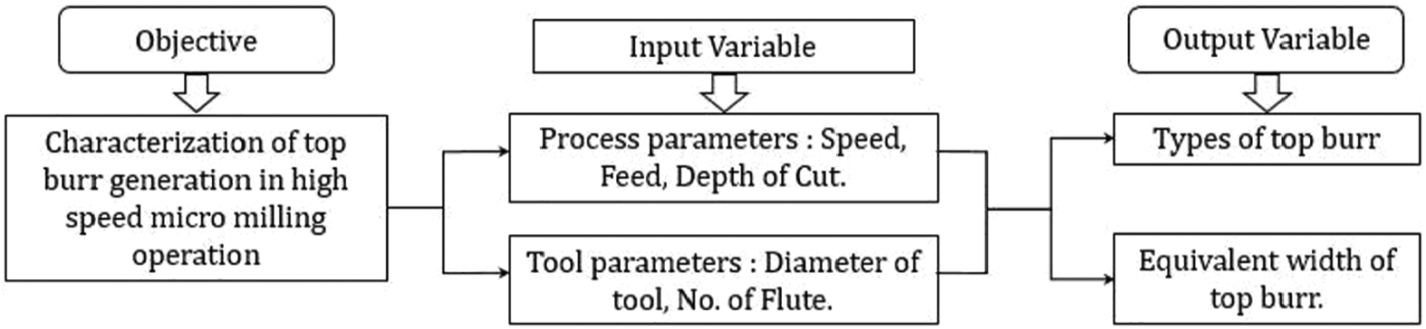
Flowchart of the experiment.
Detail of experiments
The experimental work was conducted on Ti6Al4V alloy which consists of 90% titanium, 6% aluminum, and 4% vanadium. Its microstructure before machining shows α-β phase with average grain size of 14 μm (Figure 3).
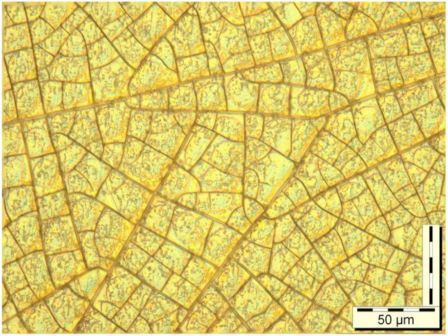
Microstructure of Ti6Al4V alloy.
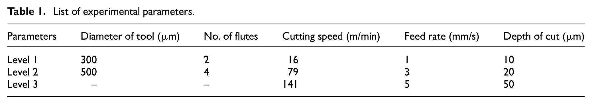
A specimen of dimension 25 mm × 25 mm × 3 mm was used for the experiment. Two uncoated tools having diameter of 300 and 500 µm were used to investigate the consequences of different process parameters on the top burr generation at a conventional and high-speed cutting. The appropriate range of the process parameters was found by Initial experiments. Table 1 shows the set of process parameters, which may affect the mechanism of burr formation. A wide range of spindle speed and feed rate were recognized. The cutting speed of spindle ranges between 16 and 141 m/min, while the feed rate ranges between 1 and 5 mm/s, which outcomes in maximal thickness of chip of 0.3–15 µm. So, the investigations are certainly reasonably aimed at a variety of parameters. Table 2 shows the sequence of machining operations performed with three repetitions to minimize the experimental errors.
List of experimental parameters.
Detail of experiments.
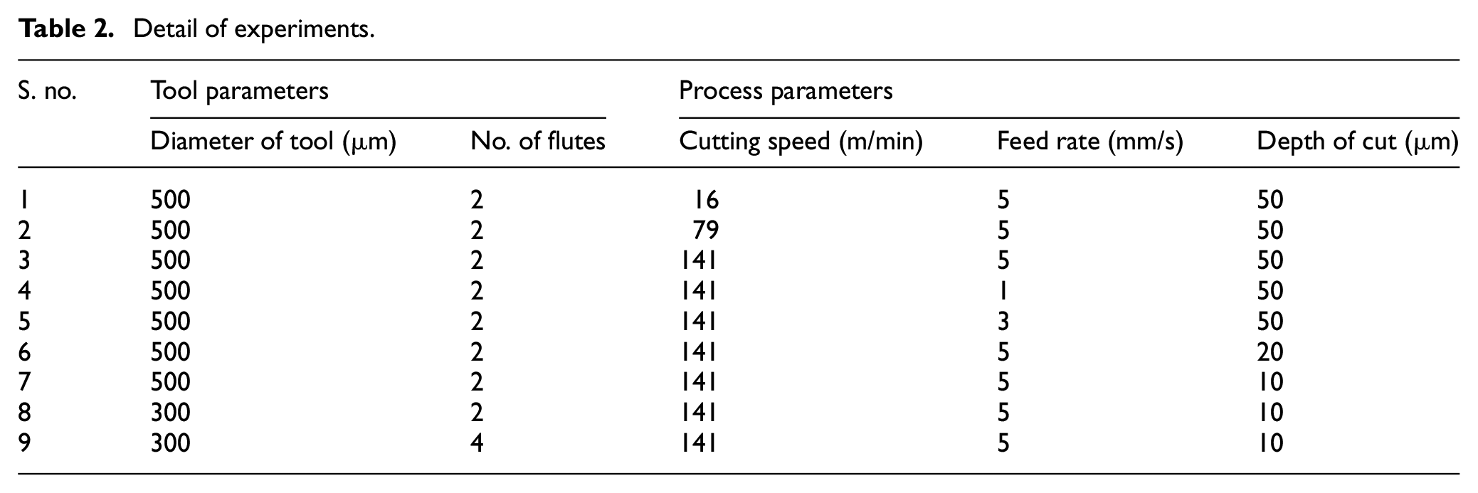
Simultaneously, parametric studies have been performed by varying each parameter, at the same time keeping other parameters constant. Three levels of cutting speed, depth of cut, and feed rate have been used. In the experiments, two sets of tools with different diameters and number of flutes have been studied. The characterizations of top burrs have been investigated through scanning electron microscopy (SEM).
Experimental setup and procedure
The experiments have been carried out on the HSMM machine as shown in Figure 4. The three-axis micro-milling machine has stacked X-Y stages with positioning resolution and accuracy of 0.5 µm and ±1 µm, respectively, while Z stage—which is pneumatically counterbalanced—has positioning resolution of 5 nm. HSMM has a ceramic bearing spindle with a maximum speed of 140,000 rev/min, average torque of ∼4.3 N cm, and tool run-out of 1.5 µm. The whole setup is placed on the vibration isolation table. A modular fixture vise has been used to clamp the workpiece of Ti6Al4V. The uncoated end-milling cutters of tungsten carbide (WC) with a helix angle of 30° were used in the experiment. Tungsten carbide micro-tool (manufactured by Axis tool®, India) of two different sizes such as 500 (two flutes) and 300 µm (two and four flutes) along with fine grain of less than 0.4 µm have been used in the study. Micro-slots have been machined on the workpiece with the length of 5 mm and a width equivalent to the diameter of tool.
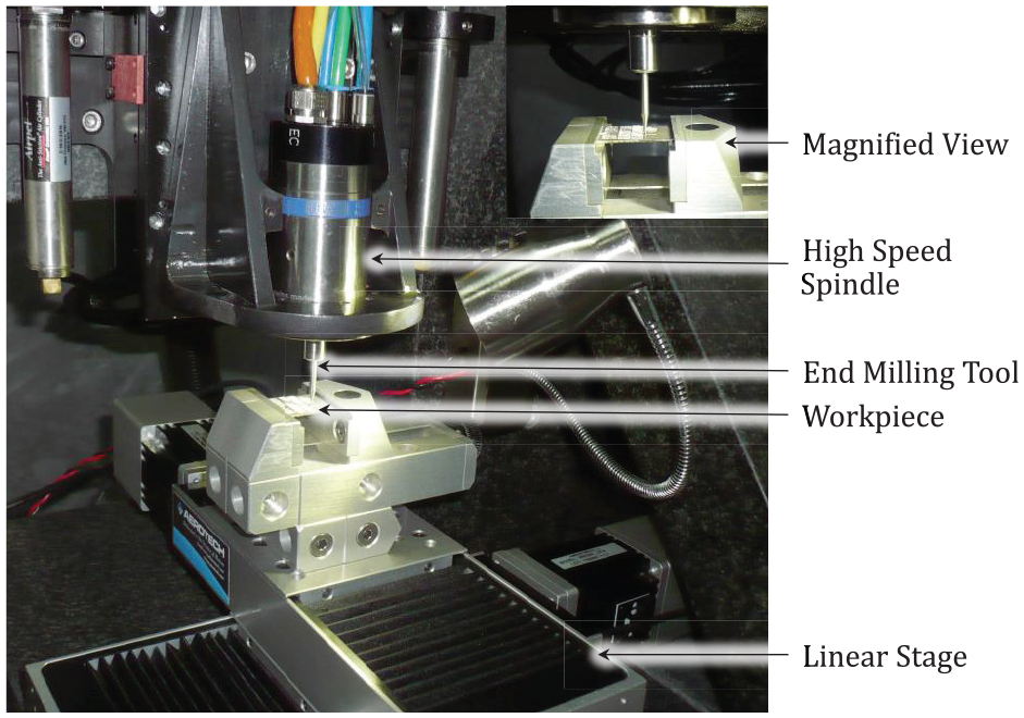
Experimental setup.
Measurement of burr
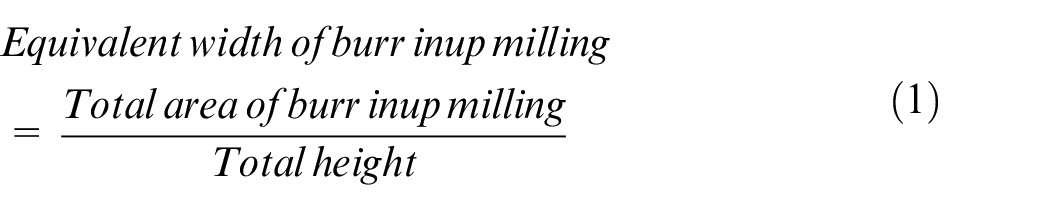
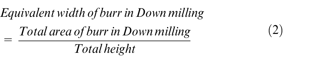
To eliminate or scale down burrs successfully, the measurement of burr must be done with high accuracy. The sharp and uneven in shape burrs are generated in the machining process, which is hard to measure. The secondary operation of burr removal such as deburring is mainly depended upon the size and geometry of burr. 42 The accuracy of burr measurement affects the selection of an appropriate method for its removal and power consumption in deburring operation. The SEM image of burr formation in the HSMM of the Ti64 alloy is shown in Figure 5. It can be observed from the figure that the burr width is varying significantly, and the variation between the width 2 and the width 1 is measured to be around 50%. Therefore, it is very difficult to consider the exact width of burr generated in up-milling as well as in down-milling machining process. There may be a chance to get an incorrect reading. Therefore, a new term introduced to find the top burr width, that is, equivalent width. Equivalent width is calculated as the ratio of total area of burr generated to total height. MATLAB® has been used to measure Area and height of the SEM image of top burrs. Mathematically
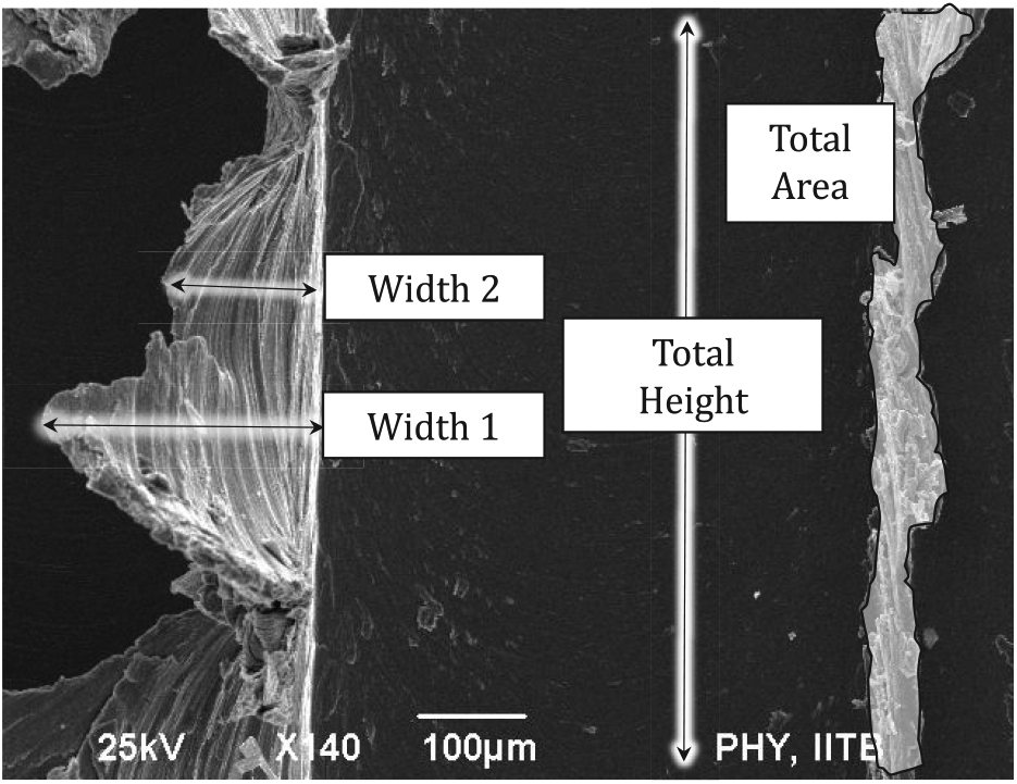
Scanning electron microscopy (SEM) image of top burr generation in Ti6Al4V.
Top burr characterization and analysis
Burr generation in machining has been identified at three main locations: top surface on machined groove, entry, and exit of the tool. Top burr has basically two types, that is, up- and down-milling top burr. The up-milling burrs are generated on the up-milling side, where cutting and feed direction are opposite to each other. While down-milling burrs are formed on the down-milling side, where both cutting and feed are in the same direction. Since the study is mainly focused on the top burr formation and their characterization. Therefore, the influence of process parameters upon the top burr size in up and down milling at traditional and high-speed cutting have been studied. Figure 6(a) and (b) shows the top burr formation at traditional cutting speed (16 m/min at 10,000 rev/min) and at high-speed machining (141 m/min at 90,000 rev/min), respectively.
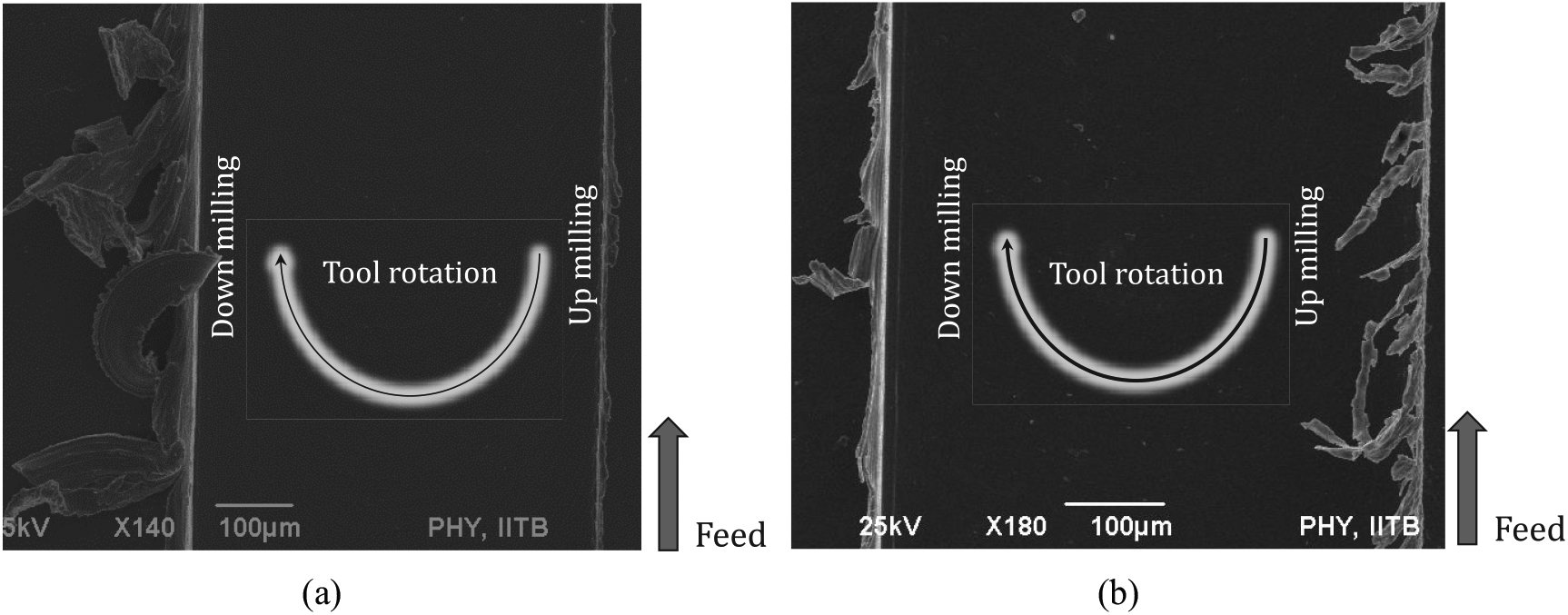
Burr formation: (a) traditional cutting speed and (b) high-speed cutting.
Burr generation at traditional speed
Figure 5 illustrates the top burr formation at a traditional cutting speed of 16 m/min at 10,000 rev/min, the linear feed rate of 5 mm/s, and depth of cut of 50 µm. It is obvious from the figure that the down-milling operation produces more burr than the up-milling operation. The burr area evaluated in down milling is between 67,600 and 81,220 µm2 with height of 700 µm. The burrs are generated in down-milling side due to squeezing and accumulation of uncut chip in milling operation. 43 These burrs are discrete in nature and thick in size. In comparison, very fewer burrs are generated in the up-milling. In similar conditions, the burr area evaluated in up milling is between 7348 and 12,420 µm2 with height of 700 µm.
Burr generation at high-speed cutting
In HSMM, the mechanism of burr formation is examined at cutting speed of 141 m/min (spindle rotation of 90,000 rev/min), feed rate of 5 mm/s, and depth of cut of 50 µm. The measured burr area in down milling ranges from 20,000 to 53,000 µm2 with average height of 600 µm. In similar condition, the measured burr area in up milling ranges from 22,000 to 33,000 µm2. Figure 6(b) illustrates the formation of top burr at high-speed cutting. It can be observed from the figure that longer burrs are formed in up-milling side as compared to down-milling side. The burr formed in high-speed cutting completely differs from the traditional cutting. It shows small burr in down-milling region and bigger thin burr in up-milling region as compared to traditional cutting. In up-milling operation, thicker burrs are found at bottom side compared to the top side, and they are facing toward the milled slot. These thin and long burrs show the material removal mechanism at high cutting speeds. A similar condition has been observed by Kiswanto et al. 19 In HSMM of Ti6Al4V alloy, adiabatic shear band is generated because of low thermal conductivity and heat accumulation, which results in burr formation and discrete chip generation.44,45
Parametric study
The top burr in micro-milling is the most critical, as it is formed due to squeezing and bulging of uncut chip material and affects the overall performance of the component or machined part. For burr minimization, parametric studies have been carried out to investigate the consequence of different parameters on the burr formation. An analysis of the equivalent width of up and down milling has been carried out to examine the influence of process and tool parameters. Figure 5 illustrates the top burr formation and measurement of the equivalent width of up and down milling.
Influence of process parameters on equivalent burr width
Figure 7(a)–(c) shows the influence of process parameters on the equivalent width of the top burr in up as well as in down milling. Figure 7(a) illustrates the influence of cutting speed on the equivalent width of top burr in up as well as down milling. The depth of cut and feed rate are taken as 50 µm and 5 mm/s. In up milling, the cutting speed is directly proportional to top burr equivalent width. As cutting speed increases from 16 to 79 m/min and further from 79 to 141 m/min, corresponding equivalent width increased by 95% and 22%, respectively. It has been found that reason for increment in equivalent width is the higher strain rate hardening of the material. 46 In down milling, as the cutting speed increases, the top burr equivalent width decreases. The equivalent burr width decreased by 33% and 10% under the same variation of cutting speed. The decrement in burr size has been found due to an increase in material plastic strain rate and decrement in the uncut chip thickness with an increment in the cutting speed. 47 Figure 7(b) illustrates the influence of feed rate on the equivalent width in up-milling as well as in down-milling processes. The equivalent width of up milling decreases by 3% with changes in feed rate from 1 to 3 mm/s at 141 m/min and depth of cut of 50 µm. Similarly, if the feed rate varies from 3 to 5 mm/s, there is a negligible decrement of 2% in equivalent burr width. In down-milling side, the equivalent width is decreased by 12% and 51% with changes in feed rate from 1 to 3 mm/s and 3 to 5 mm/s, respectively. Figure 7(c) illustrates the influence of the depth of cut on equivalent width in both the cases at cutting speed of 141 m/min and feed rate of 5 mm/s. In up-milling side, equivalent width gets decreased by 49% and 29% if the depth of cut increases from 10 to 20 µm and 20 to 50 µm. In high-speed up-milling process, more heat is diffused to the workpiece, which causes the change in metal properties, that is, increased ductility. The material is easily elongated along the direction of force applied by the tooth of the milling cutter. If the material has a low area for resistance to deform, then more burr is produced. The depth of cut increases the uncut chip area for resistance to deformation, hence less burr is produced. In down-milling side, equivalent burr width increases with increase in depth of cut. The equivalent burr width of down milling increases by 83% and 9% for a similar condition. In down milling, less heat diffused so there less influence of thermal softening. In the process of down milling, more uncut chip area is produced and, as a result, more burr is formed.
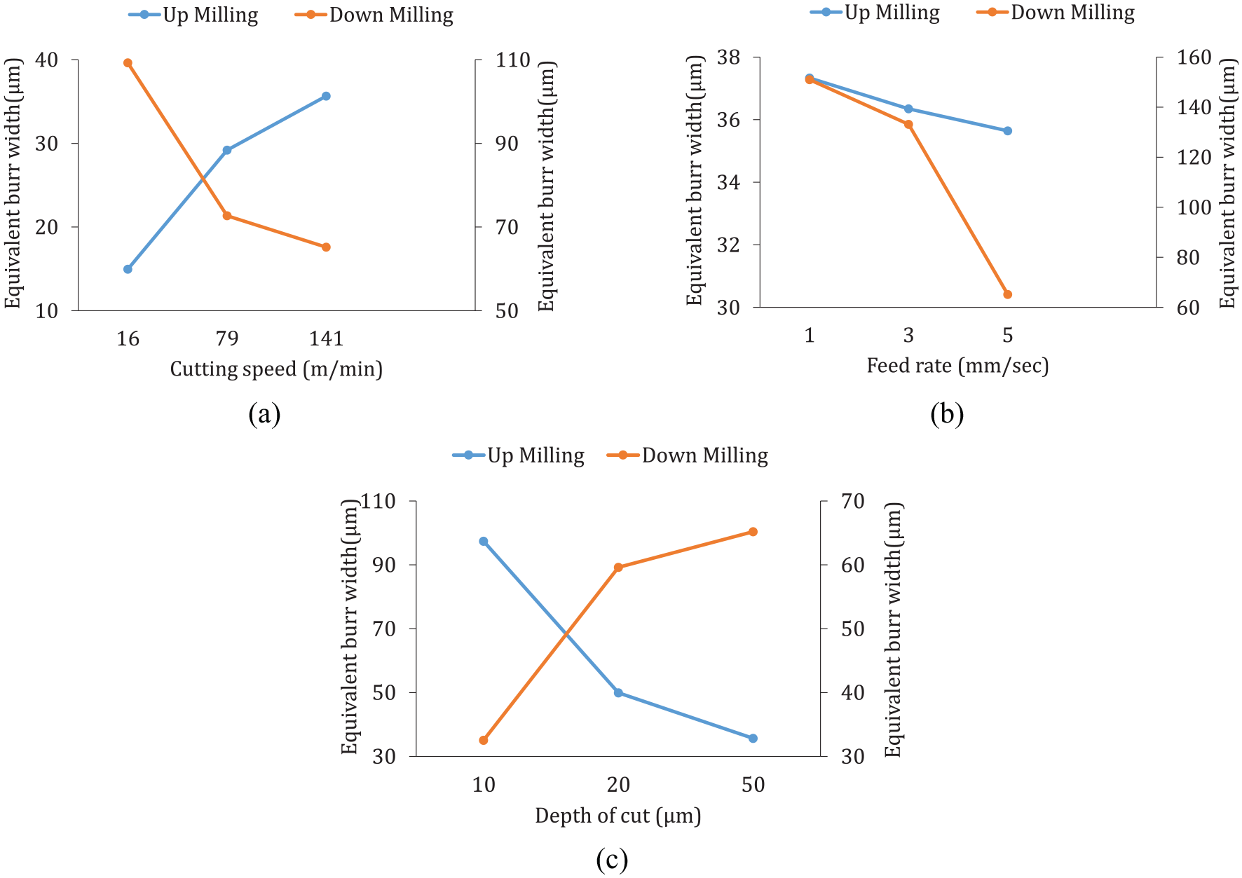
Variation in the equivalent width in up and down milling with (a) cutting speed, (b) feed rate, and (c) depth of the cut.
Influence of tool parameters on equivalent burr width
Figure 8(a) and (b) illustrates the influence of variation in tool parameters on the top burr size. As shown in Figure 8(a), equivalent burr width increased by 64% and 15% in up and down milling with changes in diameter of the tool from 300 to 500 µm, respectively. The small tool diameter has to remove less material and therefore small burr is produced, vice versa happened for larger tool diameter. 48 In Figure 8(b), 65% and 44% reduction observed in the equivalent burr width in up and down milling, when the number of flutes increased from two to four. The reason for the decrement in the burr formation might be a reduction in feed per tooth and uncut chip area.
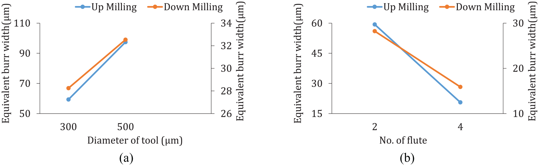
Variation in the equivalent width of up- and down-milling burr width by (a) diameter of tool and (b) number of flutes.
Conclusion
The experimental study reveals the characterizations of burr formation at HSMM. MATLAB has been used to calculate the average burr size on machined surfaces by considering the overall area of formed burr and total height. The measured top burr is termed as “equivalent width.” The influence of process and tool parameters on burr size has been examined. Following conclusions have been obtained from above results:
Burr was observed in all micro-milled part. However, a top burr in the milling is most critical burr among all types of the burr because it directly affects part function and assembly.
The measured width of top burr illustrates that the up-milling burrs are bigger in HSMM, and the down-milling burrs are bigger in conventional speed. As in HSMM, up-milling burrs are formed due to increase in strain rate hardening of material, while at conventional speed, down-milling burrs are bigger due to squeezing and accumulation of uncut chip.
The equivalent width of up-milling burr increased drastically when cutting speed increased from 16 to 79 m/min and increased slowly when cutting speed increased from 79 to 141 m/min, vice versa is happened in down-milling operation.
Increasing depth of cut decreases the equivalent width of up-milling burr and vice versa occurs on the down mill side. It may be due to effect of thermal softening at higher depth of cut.
The influence of feed rate is negligible in up-milling burr width. However, the width of down-milling burr is decreased by increasing the feed rate.
The equivalent burr width obtained reduced in both cases of up and down milling when tool diameter decreases and number of flutes increases. Smaller tool diameter has to remove less material and hence lesser burr is formed. While with the increase in the number of flutes, feed rate increases in the same proportion due which uncut chip area gets reduced and hence less burr size is formed.
This experimental parametric study may help in deciding optimum parameters for burr minimization in micro-milling of Ti6Al4V alloy.
Footnotes
Declaration of conflicting interests
The author(s) declared no potential conflicts of interest with respect to the research, authorship, and/or publication of this article.
Funding
The author(s) disclosed receipt of the following financial support for the research, authorship, and/or publication of this article: This work was financially supported by the Department of Science and Technology, Govt of India. File number: ECR/2016/001956 and project number DST (SERB)/(178)/2017-2018/533/MECH.ENGG.