
Abstract
Incremental Sheet metal Forming (ISF) is a reliable process of converting a blank to work piece with better outputs compared to conventional forming process. The flexibility of ISF in producing the rapid prototype based on the customer needs is increased which is also desirable in the industry. But Single Point Incremental Forming (SPIF) process takes more time to form a product and hence the longer time is a barrier in implementing this process in industries. In this research work, the ISF process was made on sheet metal SS 202 using a newly designed multi-point tool and the obtained outputs were compared with the same material of sheet metal formed by traditionally available single point tool. This Multi Point Incremental Forming (MPIF) process takes lesser process time to give better formability, improved wall angle and good surface roughness. The input process parameters selected for the process are type of tool, speed, feed, Vertical Step Depth (VSD), and lubrication. They are arranged by using the taguchi Design of Experiments (DOE) approach. The responses considered are wall angle, formability, surface roughness, spring back and forming time. The multiple outputs obtained were optimized by Grey Relational Analysis (GRA) to predict the superior parameter. Confirmation test was also made to validate the output result. Fractography analysis was carried out to predict the fracture mechanism obtained during the forming process. The surface topography was also made on the surface of the formed area of the sheet metal. This research work concludes that newly designed MPIF outperforms SPIF.
Keywords
Introduction
Sheet metals are stamped in automobile industries based on the need for customers and industrial specifications with the help of dies and punches. The tool cost for manufacturing die is comparatively low in the mass production whereas the cost of the tooling is high in case of small batches. Since the press tooling is made up of a specific shape to form the sheet metal as per the requirements and it can produce only that particular shape. But, the shapes can be updated in ISF by modifying the tool profile control program whenever the necessity arises. The ISF is capable of producing components with higher complexity those cannot be produced by conventional press forming process. By using the CAD software, shape of the product is initially developed and the program codes are generated, which controls the tool path and tool movement in the ISF process. A hemispherical headed forming tool (or) ball forming tool is used for the deformation of the sheet by moving it with a contoured tool path on the sheet metal. The tool moves in x-y-z directions along the programmed path as per the requirement of the workpiece to be produced. The tool path profile consists of a contour and the succeeding contours are offset down by incremental levels set. The tool movement is based on the Cartesian coordinates, which specifies each point exclusively with two points in the plane. The tool movement in the horizontal direction is controlled by x-y axes and the vertical movements are controlled by z axis. The vertical movement is controlled by the VSD which has a prime role in deformation of the material. In general, the forming industries prefer to develop a component in lesser time and of good economy. Selection of desirable process parameter plays a vital role to reduce the time and to curtail the development cost. Recently, many researchers addressed the ISF with the use of input process parameters to improve the output responses. The tool optimization technique has also been used to enhance the outputs of the SPIF process. Some important observations have been made by detailed literature study and listed here to perform this research work. Yoganjaneyulu et al. 1 proposed an experimental test with titanium grade 2 with various process parameters to find the strain rate while forming the sheet metal. After various analyses, authors concluded that shear stress plays a vital role in forming fracture on sheet metal. Zhang et al. 2 studied the formability, micro hardness and tensile strength of the sheet metal AA7075-O using friction stir incremental forming process with input process parameters of various tool rotation. By using two forming shapes namely truncated funnel and pyramidal frustum it was concluded that when rotational speed increases simultaneously the formability also increases. Yanle et al. 3 focused on various mechanical properties and thickness distribution of the sheet metal on the formed area using the input parameters like VSD, thickness of the sheet and tool diameter. The authors concluded that thinning rate is reduced with lower VSD and larger tool diameter. Pandivelan and Jeevanantham 4 and Baruah et al. 5 studied the formability and surface roughness of aluminum alloy AA5052 by forming the sheet metal in three different directions such as rolling, transverse and diagonal. They used GRA to predict the optimum value. Raju and Narayanan6,7 examined a multiple sheet metal forming process using taguchi based DOE method to predict the optimum level of parameters which will improve the output responses in forming process. The authors proved that multiple sheets reduce the time taken to complete the forming process and the characteristics analysis was also made on the sheet metal towards the formability of sheet metal. Kurra and Srinivasa 8 developed a numerical simulation attempt on ISF by creating the finite element model of various shapes using LS-DYNA software. The output values obtained during simulation process were used to justify the experimental values. Echrif and Hralri 9 created a negative ISF process with four inputs namely feed rate of the tool, VSD, speed, and tool diameter. Using these input parameters the obtained outputs were optimized using taguchi based DOE approach to improve the surface finish of the final product. At earlier periods, only metallic materials were formed by ISF process but Franzen et al. 10 and Martins et al. 11 made a new attempt with polymers like polyvinylchloride and Fiorotto et al. 12 made an investigation on composite materials in forming process. The authors proposed that the use of composite materials in industries may reduce the manufacturing cost in small batch production and also in rapid manufacturing process. Jackson et al. 13 investigated the formability of sandwich panels using incremental sheet metal to make its usage feasible in ISF process. Palanisamy and Senthil 14 suggested GRA is a tool which can effectively solve the multi-objective response. Ramesh et al. 15 demonstrated that the GRA is an efficient tool to assess the performance of intricate project minimal data. Srinivasan et al. 16 proposed that GRA is a simple and effective method for converting multi objective responses into single objective response. According to the literature survey sheet metal thickness, tool feed rate, ball diameter, rotating speed of the tool, VSD and lubrications were some of the input parameters considered for the forming process. By varying this process parameters17–19 the formability, wall angle, surface roughness on the formed area and spring back were obtained as responses and towards these outputs only more research is prolonged. Hence it can be noticed that many researchers attempted to improve the output responses of ISF through the input process parameters and very few research works only found towards the geometry of the forming tool20–22 in order to improve the outputs of the sheet metal. These researchers made modifications in the tool but used only single or two points of contact between the tool and sheet metal. Therefore for this research a tool which makes six contact points between the tool and sheet metal is designed. This multipoint tool is examined on the sheet metal and the outputs were compared and validated with the existing single point tool. The main objective of this multipoint tool is to improve the number of localized deformation point with the help of increased contact points on the sheet metal during the forming process. In this research work study, austenitic stainless steel 202 is selected due to its advantages like more corrosion resistant and various applications towards architectural trims, marine exteriors, chemical processing equipments etc. The output responses obtained from SPIF tool were compared with MPIF tool with the help of multi-objective optimization technique. Taguchi DOE based L18 orthogonal array was created to compare the SPIF and MPIF using the software MINITAB 17. The input process parameters such as feed (f), speed (v), VSD (Δz), and lubrication were used to form a hyperbolic shape using the multipoint and single point tool. After forming process, the output responses like wall angle, formability, surface roughness, spring back and forming time were recorded. Using GRA technique the obtained multiple responses were converted into single response to find the optimal parameters. This work makes an effort to attain the optimal values from the input process parameters used by comparing the MPIF with SPIF. The Scanning Electron Microscope (SEM) image is also observed on the formed area to compare and justify the optimization result using fractography and surface topology.
Materials and methods
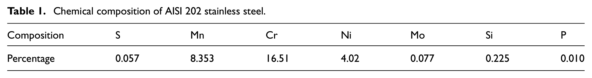
The material SS202 is been purchased from the market and its chemical composition were obtained through spectrometric analysis as given in Table 1.
Chemical composition of AISI 202 stainless steel.
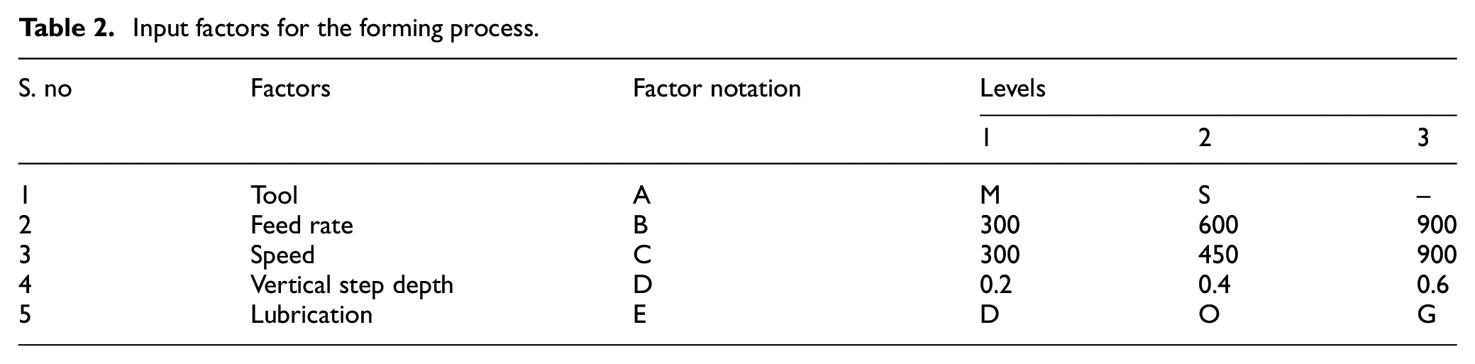
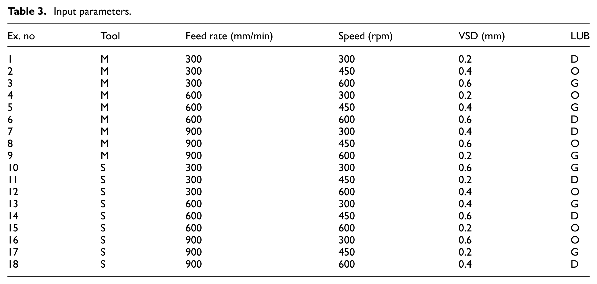
A sheet with thickness of 0.5 mm was sheared to the dimension of 150 mm × 150 mm. A rectangular array consisting of 2 mm diameter circles with 1 mm gap between adjacent circles have been engraved on the sheet using laser. The ball ended forming tool made of EN 18 was used for forming operation. The ball of diameter 12.7 mm was used for both SPIF and MPIF. The sheet metal with laser markings was mounted on the forming fixture as shown in Figure 1. The input parameters were fed to the CNC machine through the program used to perform the forming operation. In the Table 2 various levels of input factors namely type of tool, feed rate of the tool movement, tool rotational speed, VSD were given along with the lubricating conditions like Dry (D), Oil (O), and Grease (G) maintained during the forming process. Using these input parameters a mixed level L18 Orthogonal Array (OA) was created as shown in Table 3. During the forming process the circular laser grids marked on the surface of the blank gets gradually converted into elliptical shape with every downward increment of the tool. Video measuring machine was used to measure the major true strain (ε1) and minor true strain (ε2) values from the randomly selected five elliptical grids near the fractured area. The sum of strain values was calculated using modified Cockroft-Latham criterion. 23 The average of this sum of strain values were taken as formability value.
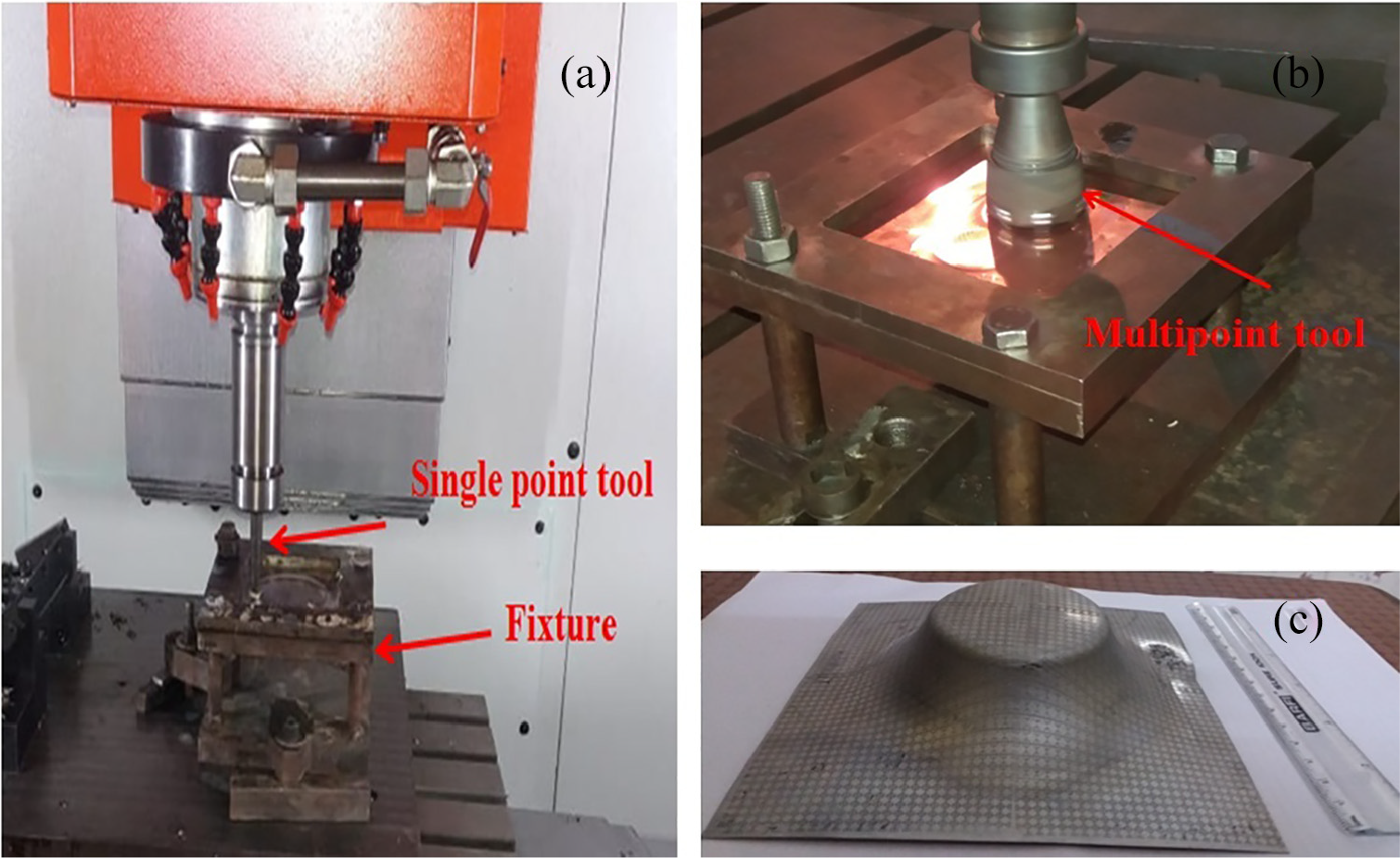
Experimental setup of (a) CNC machine with single point tool used, (b) multipoint tool, and (c) hyperbolic shape formed on the sheet metal.
Input factors for the forming process.
Input parameters.
The CNC machine automatically calculates the time taken to complete each process which is considered as processing time. The surface roughness tester named RUGOSURF 10G is used to measure the roughness on the formed area as shown in Figure 2.
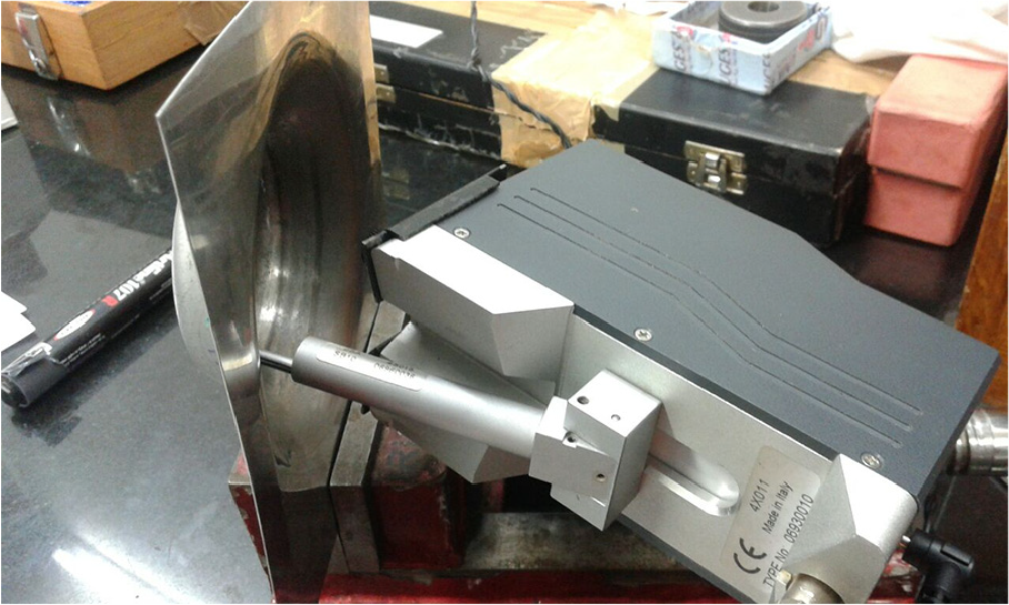
Roughness tester used for measuring the surface roughness.
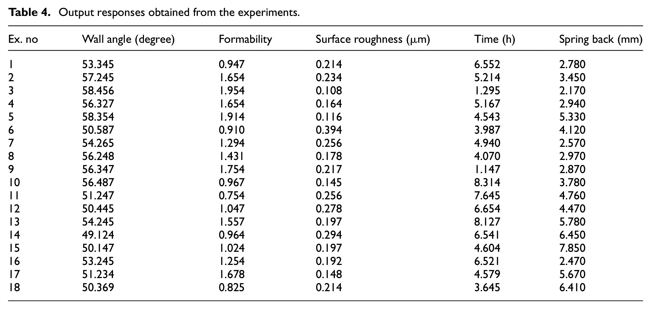
Five repetitions made on the roughness value in a uniform pattern and the average is considered for further calculation. Spring back is measured by calculating the difference between the depth moved by the tool along Z-axis and the depth value was measured on the formed area by coordinate measuring machine (Make: Tesa micro hite 3D of accuracy 4 µm) are shown in Table 4.
Output responses obtained from the experiments.
Results and discussions
The outputs obtained from the experimented sheet metals were discussed below using the techniques GRA, fractography, and surface topology to find the best forming tool.
Optimization analysis
The multiple outputs obtained from the combination of input parameters were converted into single objective by using GRA method. The following steps are to be followed in GRA6,14 to obtain the optimal value of the various inputs used,
Step 1:
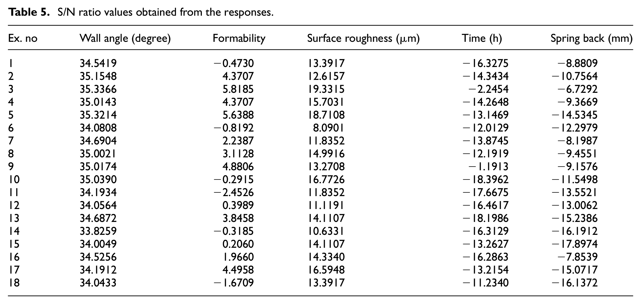
The S/N ratio was found using the formula given below. Using the equation (1) higher better response is obtained for wall angle and formability since a better precision of formed sheet metal should have higher wall angle and formability. Higher wall angle improve the thickness distribution occurrence during forming process which will also improve the part height to be formed. For surface roughness, spring back and forming time the material should produce minimum value for better output therefore smaller-the-better response is to be used which is shown in equation (2) and the values were shown in Table 5.
S/N ratio values obtained from the responses.
To find S/N ratio for higher better response the equation used is,
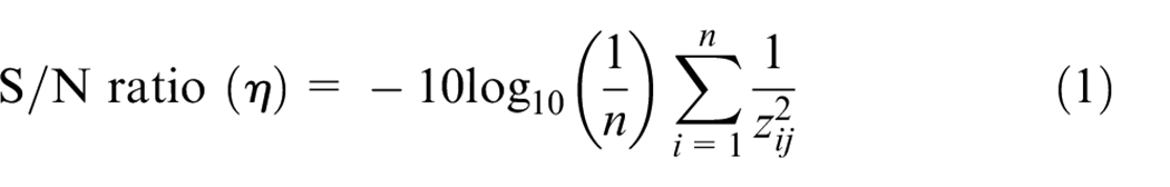
To find S/N ratio for smaller better response the equation used is,
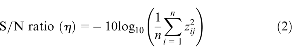
where, n is the number of replications and Zij is the normalized response data. These values can be directly applied in equations (1) and (2) for further calculation for i = 1,2,3,…,n; j = 1,2,3,…,k, here k is the proportionality constant which depends on the financial criticality of quality characteristic.
Step 2:
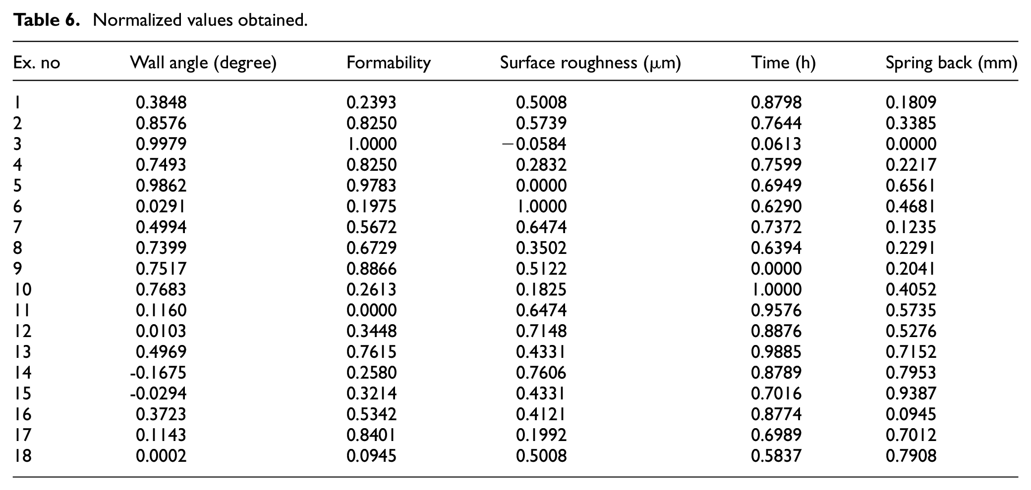
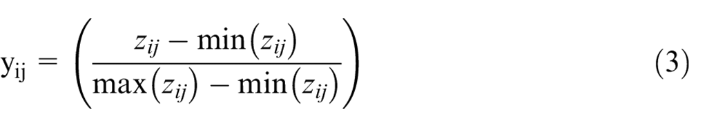
The normalization is done with the data obtained from the S/N ratio using the equations (3) and (4) and the values were shown in Table 6,
Normalized values obtained.
For higher better response the normalization equation used is,
For smaller better response the normalization equation used is,
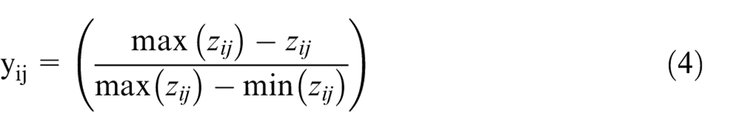
where yij is the sequence after the data pre-processing. If the sequence is infinite then equation (3) used for normalization else that is if the sequence is finite, then equation (4) used. The normalized data using equations (3) and (4) are presented in Table 6, in which one can find Δmax (which is 1) and Δmin (which is 0). The variables calculated using equations (3) and (4) carry forwarded for calculating the grey relational coefficient in equation (5)
Step 3:
By using the normalized values in the equation (5) the Grey Relational Coefficient (GRC) is obtained as,
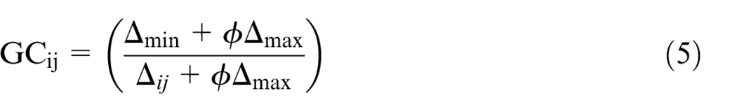
where, Δmax is 1, Δmin is 0, Δij is the absolute value of the difference between the ideal sequence and the sequence considered for the calculation,
Step 4:
The Grey Relational Grade (GRG) is calculated using the equation (6),
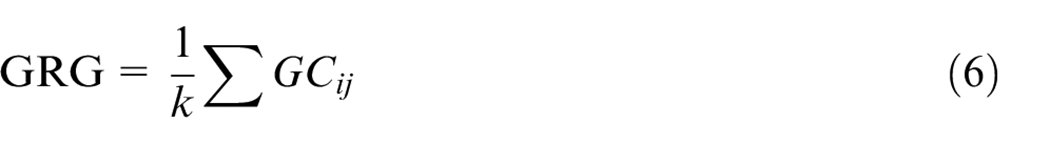
where k is the number of quantities used. The highest value of the GRG gives the optimal solution.
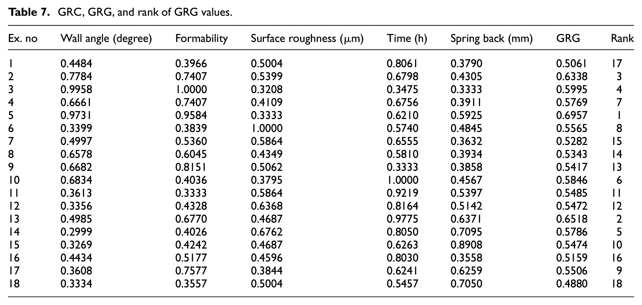
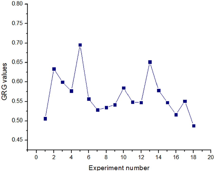
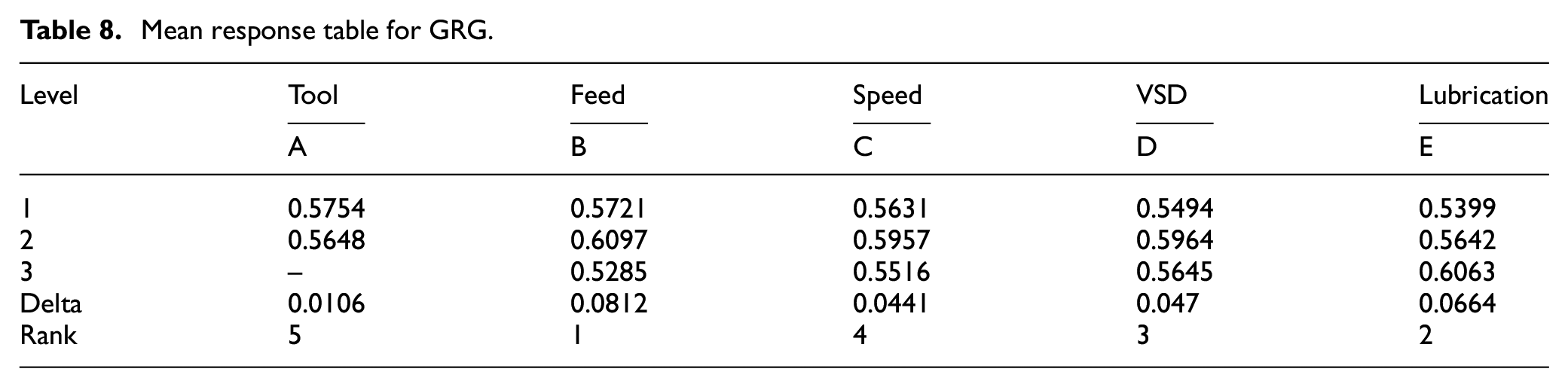
The obtained GRG values were shown in Table 7 and the rank is given in the descending order. From the information given in Table 7, it was observed that experiment number 5 gives highest output value which is also shown graphically in Figure 3. Therefore the input parameters of experiment number 5 are considered as the optimal values. In experiment number 5, the input parameters found were multipoint tool, 600 mm/min feed rate, 450 rpm spindle speed, 0.4 mm VSD and the lubrication is grease. The mean response values generated using MINITAB 17 is shown in Table 8. The main effect plot for GRG with larger the better response, is shown in Figure 4 in which the MPIF shows higher mean response. Similarly in feed rate the 600 mm/min gives better result followed by the 300 mm/min and 900 mm/min. In case of speed of the tool 450 rpm gives superior response compared to 300 rpm and 600 rpm. In VSD 0.4 mm gives improved response followed by 0.6 mm and 0.2 mm. In all the above three cases it can be noticed that the intermediate value gives better responses. In case of lubrication, grease is better which may be due to its higher viscosity level. The influence of controllable factors was analyzed using the ANOVA table in which the p-value of lesser than 0.05 influence the output responses more. The R2 value of GRG is also found as 96.89% and R2 (adj) is 93.39% and it has great occurrence of R2 (pre). The percentage of contribution is also given in Table 9 in which the influencing factors with maximum percentage are ordered in ascending order. This is also shown graphically in Figure 5. The feed rate influence the outputs with maximum percentage of contribution with 35.88% followed by the lubrication and speed with the values of 31.77% and 13.59% respectively. The ANOVA influence is great concurrence with the GRA.
GRC, GRG, and rank of GRG values.
Computational result of GRG values.
Mean response table for GRG.
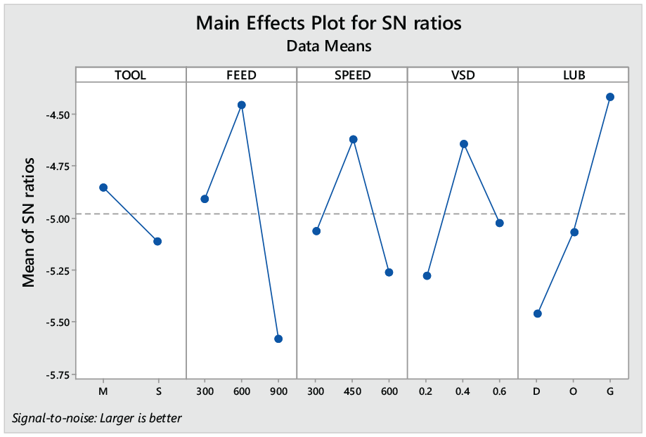
Main effects plot obtained for GRG.
ANOVA for GRG.
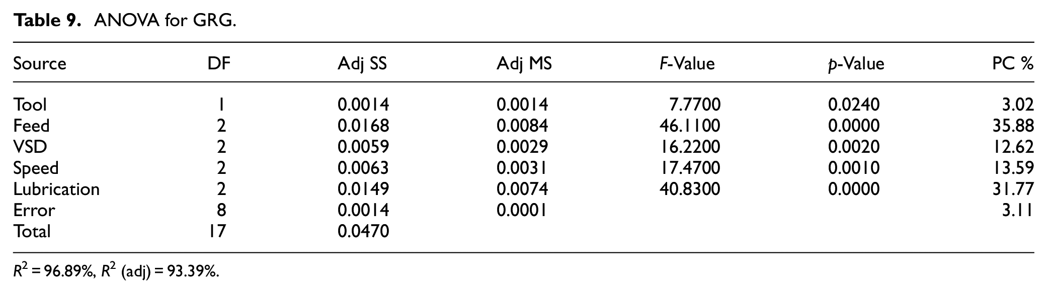
R2 = 96.89%, R2 (adj) = 93.39%.
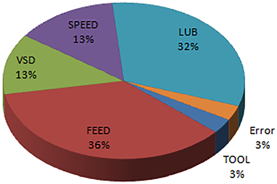
Percentage of contribution of input factors as per ANOVA using GRG values.
Confirmation test
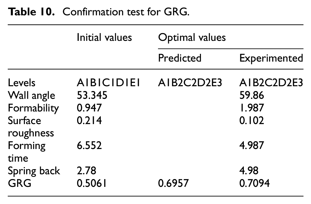
The confirmation tests were made on the optimal values to find the optimization accuracy. From the result shown in Table 10 it is found that optimal GRG has improved 1.96%.
Confirmation test for GRG.
Fractography analysis
Fractography analysis is used to predict the fracture mechanism occurs during the forming process. The images obtained by the SEM on the fractured area of maximum formed sheet during MPIF and SPIF were shown in Figure 6(a) to (d). By observing the fractured sheet obtained during MPIF it can be noticed that shear dimples were formed which is shown in Figure 6(a) and (b).
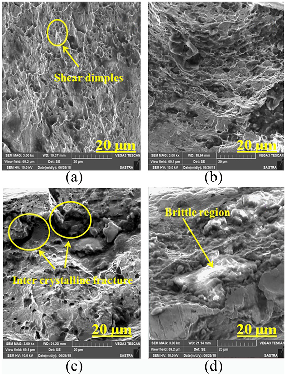
SEM image obtained on the fractured area of the sheet metal during MPIF (a and b) and SPIF (c and d) process.
The shear dimples were obtained due to the shearing action 7 of the multipoint tool. Also the elliptical voids can be noticed on the SEM images of the sheet metal formed by MPIF. From the SEM image of SPIF which is shown in Figure 6(c) and (d) it can be observed that the inter-crystalline fracture was developed in the fractured area which makes the sheet to tear at the earliest. Inter-crystalline fracture is generated because of the less shearing force generated by the single point tool. The axial load given by single point tool which acts perpendicularly to the sheet metal may also create more stress that leads to fracture of the material. In case of using multipoint tool, the shearing force is increased since more area is occupied by the tool. By increasing the area of the tool more amount of tangential force is generated. The tangential force usually acts on the side walls of the sheet metal which may create a better combination of compressive and tensile force. 24 This force may leads to better formability of the sheet metal.
Surface roughness analysis
Each formed samples from both MPIF and SPIF was selected for surface topology analysis (as per the results of Table 4). The obtained samples were first observed using SEM which is shown in Figure 7. From the image of SPIF (Figure 7(b)) it is observed that surface tear and debris are formed on the surface. Comparing this to the sheet metal formed by MPIF (Figure 7(a)), the surface finish is observed to be better. The 3D image is also obtained on the formed area by non-contact surface roughness Tester (manufactured by: TALYSURF CC lite) which shows that the surface finish obtained by MPIF (Figure 8(a)) is better than SPIF (Figure 8(b)). The roughness profile is also shown in Figure 9 in which the waviness of the Figure 9(a) is better than the Figure 9(b). According to the results, it can be concluded that the sheet formed by multipoint tool gives better surface finish. This may be due to number of balls used in MPIF tool is more when compared to the SPIF tool. The increased number of balls in the tool will reduce the ball wear which may also help in the surface quality improvement. Further this increased number of ball movement will improve the burnishing movement of the tool. 25 In addition the gouges produced on the surface of the formed area are compressed by the engagement and disengagement of the tool movement. 20
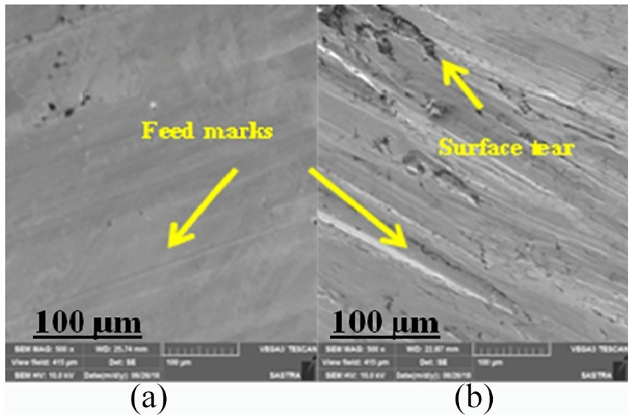
Surface roughness observed on sheet formed by: (a) MPIF, and (b) SPIF.
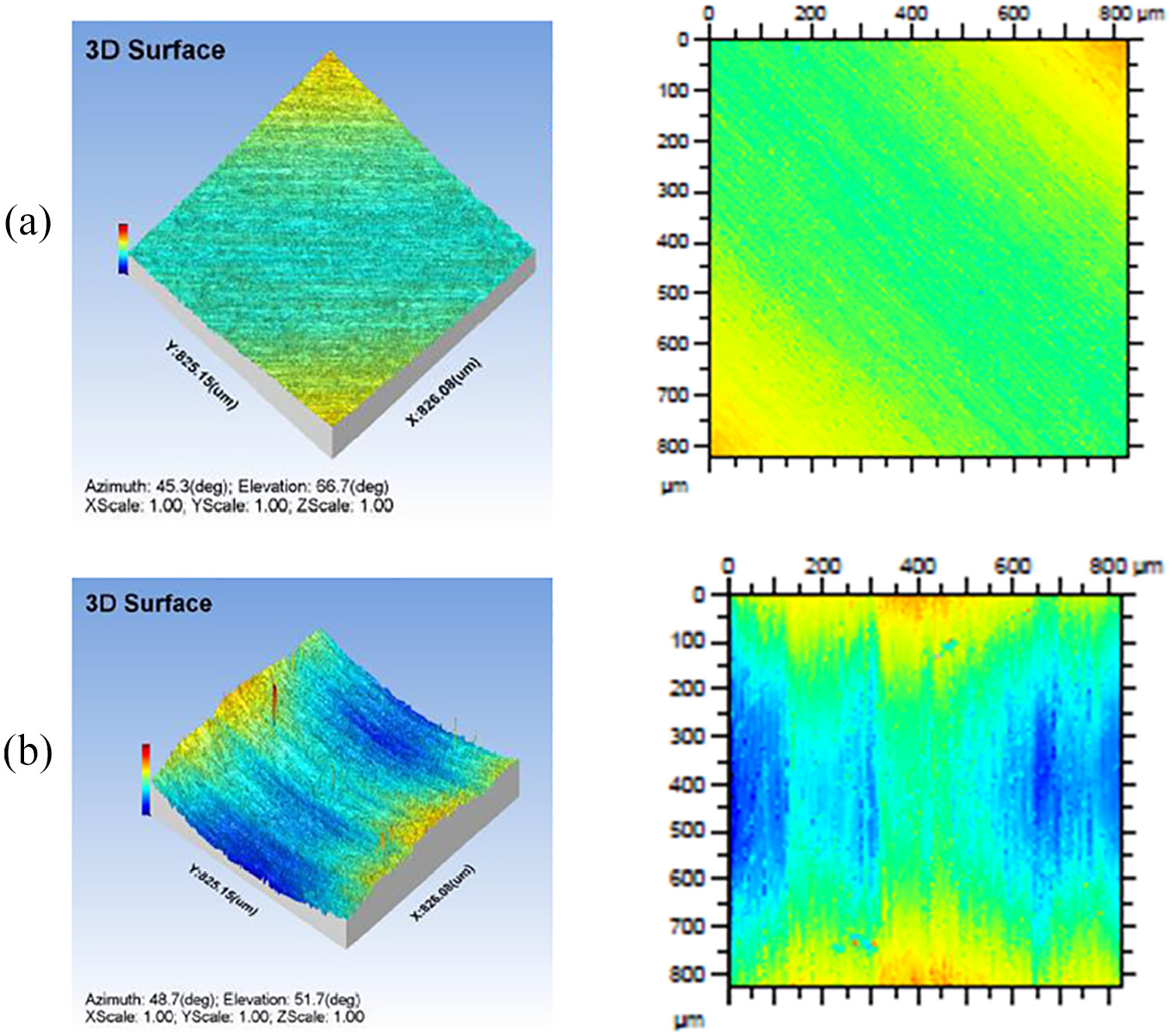
3D image obtained on the surface formed by: (a) MPIF, and (b) SPIF.
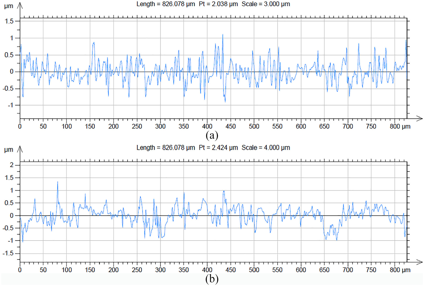
Roughness profile obtained from: (a) MPIF and (b) SPIF.
Conclusion
The research work compared the responses of MPIF and SPIF. Based on the experimental results, it was concluded that,
In L18 OA (Table 7), the input parameters multipoint tool, feed rate of 600 mm/min, speed of 450 rpm and VSD of 0.4 mm with grease as lubrication gives the optimal result.
From the ANOVA table, it is noticed that the feed rate acts as the most dominant factor with 35.88% of contribution followed by the lubrication and speed with 31.77% and 13.59% of contribution respectively.
From the mean response table, the influencing factors are ranked as feed, lubrication, VSD, speed and tool. By GRG analysis, the multi-point tool with feed rate of 600 mm/min, speed of 450 rpm, VSD of 0.4 mm and grease lubrication were yielded the better response as depicted on the main effect plot (Figure 4).
The confirmation test conducted, using the optimal input parameters, it is observed that the optimal GRG value has 1.96% of improvement.
The SEM images of the sheets formed by MPIF process shows the shear dimples which justify the formation of ductile fracture whereas the SEM images of sheets formed by SPIF process shows the inter-crystalline fracture which initiates the fracture at the early stage. The fracture in case of MPIF, may be due to the increase in shearing action produced by the multipoint contact.
The observed surface finish from SEM shows less tool feed marks in the sheet metal used MPIF, process comparing with the SPIF. It is evident that MPIF gives better surface finish when compared to SPIF. In addition, the 3D surface and roughness profile also confirm that the MPIF process gives better surface finish than the SPIF process.
Footnotes
Declaration of conflicting Interests
The author(s) declared no potential conflicts of interest with respect to the research, authorship, and/or publication of this article.
Funding
The author(s) received no financial support for the research, authorship, and/or publication of this article.