
Abstract
In this article, large direct current is applied through the tool to improve formability while forming 6061-T6 Al using single-point incremental forming. Special attention is paid to the direct effect of current density, as opposed to bulk resistive heating, to determine whether the electroplastic effect is significant in raising the formability without requiring temperature rise. Tests are performed to determine the maximum wall angle that can be formed for a variety of current and tool settings. The area of contact between the tool and sheet is modeled, and a control system is proposed and tested to vary the current to maintain a constant current density during tests. The phenomenon of current threshold density is observed at a current density range agreeing with previous studies forming the same material in different loading cases. A significant formability increase is observed at a range of current density values that agree with previously published work with this material in different loading cases. Surface roughness and spalling are also shown to be directly affected by current.
Keywords
Introduction
Single-point incremental forming (SPIF) is a dieless technique for forming complex shapes from sheet metal. SPIF, outlined in Figure 1, uses a simple, small tool making a series of passes around the outer periphery of a part to form the final shape. Unlike conventional sheet metal-forming techniques, SPIF does not require specialized tooling for each part, 1 instead uses the motion of the tool to form the desired shape. While traditional stamping is typically only economically feasible for large production runs due to the capital cost of tooling, the dieless nature of SPIF allows custom parts to be made for low cost.
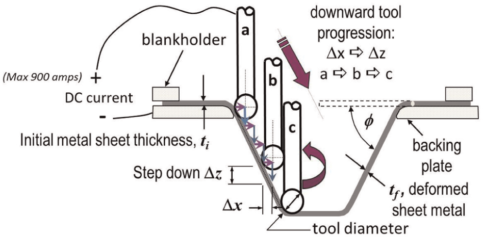
Single-point incremental forming.
In recent years, much effort has been spent on improving the ability of SPIF to form steep walls and hard-to-form materials. Babu and Kumar 2 employed SPIF to form 304 Stainless steel, and Ambrogio et al. 3 used a heated blankholder to successfully raise the maximum wall angle achievable in AZ31 magnesium. Local heating of the sheet near the forming area with a laser has also been used by Duflou et al. 4 and Göttmann et al. 5 to successfully form titanium alloys.
Both the heated blankholders and laser heating methods increase the complexity and initial cost of the forming system, and potentially reduce the usable volume of the machine. To produce a lower cost alternative which requires fewer modifications to an existing computer numerical control (CNC) mill, Fan et al.6,7 passed electric current through the forming tool, increasing the sheet temperature through resistive heating. This method was successfully used to increase the formability of AZ31 magnesium and Ti-6Al-4V. A similar system has been implemented by Ambrogio et al. 8
A common problem with metal sheet forming at elevated temperatures is reduced lubricant effectiveness and tool wear. 9 One potential method of improving the formability without directly relying on increasing the temperature of materials is electrically assisted forming (EAF). EAF is a process where the yield and flow stress of a material are reduced by electron interaction with dislocations while passing high-density current through the material during forming.10–13 Unlike resistive heating, however, the temperature rise accounts for only a small portion of the formability increase observed. 14
By recognizing that formability gains with applied current may be a result of electric current, rather than resistive heating, it may be possible to realize formability gains at lower temperature, or otherwise find the optimal forming parameters that maximize formability increase while reducing unnecessary temperature rise. Reducing the forming temperature could reduce lubricant failure and tool wear. To evaluate the effects of current density in SPIF as proposed by Roth, 15 an electrified toolholder was designed and used to test the maximum wall angle of several samples of Al 6061-T6 at varying current values. The goal of this work is therefore to establish that electric current has a direct effect of formability conditions in electrically assisted SPIF (EASPIF).
Many materials formed with EAF exhibit a threshold current density value, below which little effect is seen. 11 This study also seeks to establish whether a similar threshold current density phenomenon is present and whether it can be used to predict formability increases in EASPIF. While the method used for EAF is similar to previous work on resistive heating, the goal of this study is to determine whether electrical, rather than thermal effects dominate in increasing formability.
For this study, the maximum achievable wall angle for Al 6061-T6 is tested for a range of current (constant current magnitude) and current density (varying current as contact area changes) values for a variety of tools. The results of the formability response can be compared to literature on forming 6061-T6 with EAF. 11
Background
SPIF
During SPIF, thinning of the walls occurs due to stretching and through-thickness shear of the material. The final wall thickness tf is often approximated as a function of the initial sheet thickness ti and the wall angle φ, 16 as shown in equation (1)

As the wall angle is increased, the wall thickness decreases, resulting in a practical wall angle maximum for every material and thickness combination. Multiple passes can be used to extend forming limits well beyond that of single passes 17 by redistributing material from the center of the part to the walls, however, at the cost of drastically increased cycle time.
EAF
In EAF, high-density direct current is applied through a metal during deformation. While the current is flowing, the yield and flow stresses are significantly reduced, and the deformation limits are raised.12,18 EAF has been shown to improve the forming limits and reduce the process forces of tensile tests, 12 compression tests 11 and deep drawing. 19
As electrons pass through the material, it is theorized that they aid dislocation motion in three ways: 20 by locally heating the area around dislocations, by increasing the kinetic energy deposited on the dislocation creating an electron “wind force” and by increasing the number of electrons, allowing bonds to be broken and formed more easily. In tensile tests, EAF has been shown to increase the forming limit before fracture by as much as 200% of the nonelectrified baseline. 12
Of particular interest is that the formability gains that have been achieved are significantly higher than can be attributed to temperature alone.11,14 EAF has also been used to reduce, and in some cases eliminate springback after forming. 21
Many materials also exhibit a “threshold” current density, below which little formability improvement is seen. The cause of this effect is still not well understood; however, threshold current densities have been observed in several materials. 11 For Al 6061-T6511 in compression, the current density threshold was observed to be between 54.6 and 60.8 A/mm2. 11
Experimental method
In EASPIF, current is passed through the tip of the SPIF tool into the sheet. To test EASPIF, a custom forming apparatus was designed, capable of carrying high currents (up to 900 A) to the rotating tool, while insulating the mill spindle from any stray current. Figure 2 shows the electric circuit formed by the machine.
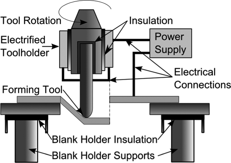
Electrical circuit used for tests.
Current is carried to the rotating tool by means of a custom toolholder, shown in Figure 3. The toolholder has copper slip rings that allow for high currents to be transferred to the rotating tool with minimal resistance.
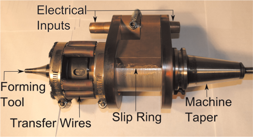
Custom slip-ring toolholder.
Tests were performed in a Bridgeport GX-480 CNC milling machine. Current was supplied by a Magna- Power TSA5-900 programmable DC power supply with an output range of 0–5 V and 0–900 A. Prior to forming, samples were lubricated with 75W-90 synthetic gear oil. Sheet temperature was measured by thermocouples attached to the underside of the sheet: one at the edge near the toolpath and one near the center. Temperatures were recorded with an Omega HHM290 temperature sensor.
Maximum wall angles were determined by using a variable wall angle conical frustum (VWACF) test, as described by Hussain and Gao. 16 The VWACF is a test shape of increasing wall angle with depth. Tests are stopped upon sheet fracture, and the tool depth is recorded at that point. The maximum wall angle can be determined from the depth of the tool at the point of fracture. The test shape used in this study varied in wall angle from 40° to 90° from horizontal, with a radius of wall curvature of 50 mm and an upper diameter of 178 mm. The VWACF test was favored due to the ability to directly and rapidly compare relative formability changes from one setting to another.
Tests were performed for three diameters of tool: 6.35, 9.57 and 12.70 mm. For the 9.57 and 12.7 mm tools, a series of tests were run at currents of 0, 50, 100, 150, 200, 300, 400, 500, 600 and 700 A. A similar set of tests was run with the 6.35 mm tool, however, with a maximum current of 500 A to protect the equipment against excessive tool heating.
Tests were first performed in order of increasing current, and no cleaning operations were performed on the tool between tests. A first run-through of these tests revealed decreasing wall angle with increasing current. Inspection of the tool tip revealed a degradation of the surface of the tool at the end of the test, with material being deposited on the surface of the tool. To ensure that the tool degradation effects were not producing a false-negative result, the second and third repetitions of each set point were performed in random order, and the tool surface was remachined and polished to a surface roughness RA of 0.7 µm between each test.
Tests were performed at a feedrate of 1270 mm/min. For the three tools, the spindle speed used was 50, 33 and 25 r/min, respectively. These speeds were selected to minimize relative speed between tool rotation and feedrate. The step-down between each pass was 0.25 mm. To determine the effects of temperature on the process, an additional set of tests were performed with cold air applied to the underside of the sheet. The cold air was supplied by a vortex tube compressed air chiller and applied to the underside of the sheet so as not to disturb the lubricant.
Constant current density
For a constant current test, the current density varies considerably through the test due to the contact patch increasing in area with wall angle. Variable current density leads to excessively high current densities near the top of the test part, and densities that may be too low near the steep sections of the test part.
To better isolate the effects of current density, a simple control system was created in MATLAB to vary the current throughout the duration of the test, ensuring constant current density. The control system reads the z-axis position from the mill, allowing the wall angle and contact patch area to be estimated. The current magnitude for that position is then calculated and used as the power supply set point until a new z-position is read.
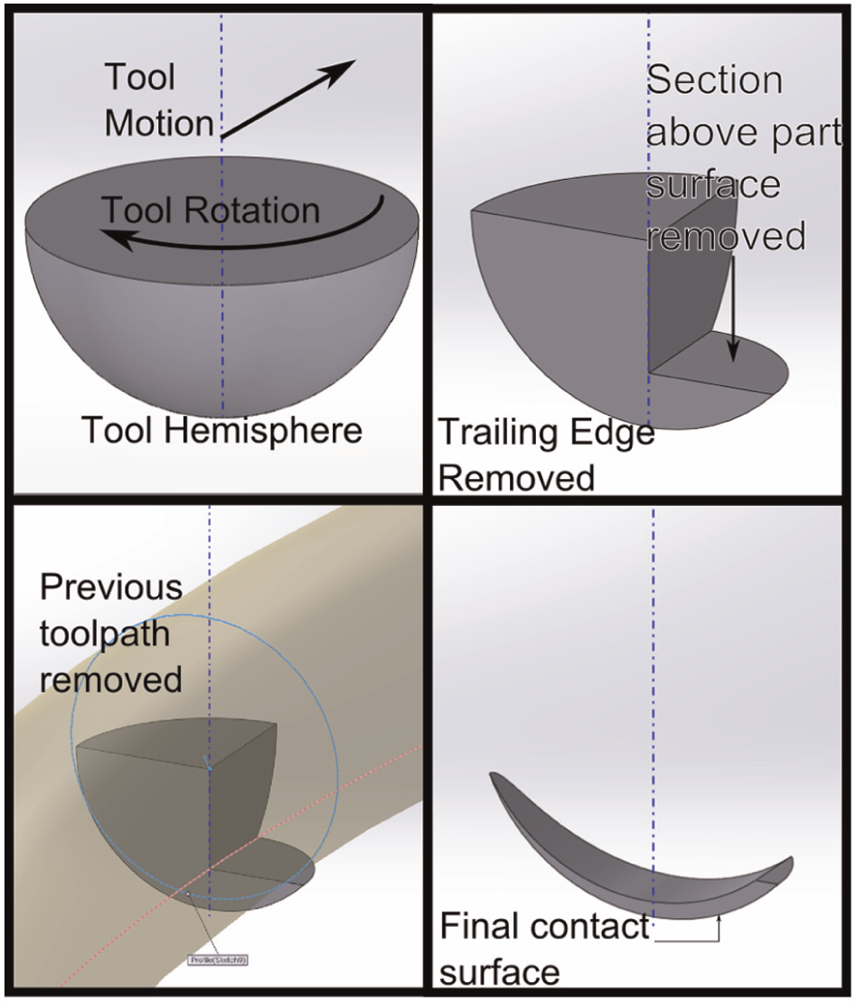
Modeling contact patch area
In order to determine the current density during SPIF, a highly simplified model was created to determine the area of contact between the tool and sheet. While models have been previously presented, 22 the model presented in this section aims to minimize computation time, allowing in-process determination of contact area for control. The following model is also designed to use geometry that can be directly measured, allowing experimental validation. Experimental validation of the following model is an ongoing area of study.
The model presented in this section is an extension of the model created by Hamilton. 23 For the purposes of simplification, the model assumes no springback of the sheet directly behind the tool and no radial deflection of the bulk part, therefore, assuming perfect adherence to the tool and path shape.
Intersection of the tool and the trough left by the previous toolpath. Tool motion is into the page.
To calculate area, the depth to which the tool indents into the sheet is first estimated. Measurements of through-sheet thickness taken by Jackson and Allwood 24 showed that the through-sheet thickness of the part directly under the tool is approximately proportional to the final thickness of the wall. The height of indentation h1 is then modeled as the difference in height due to thinning from wall angle φ, as calculated in equation (2)

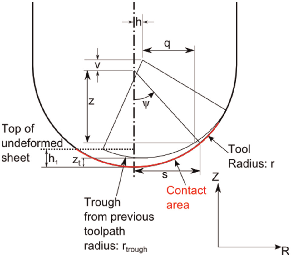
The tool is also assumed to not contact the sheet in areas that have been previously formed by earlier tool passes. To account for previous forming passes, the intersection is determined between the tool and previous forming pass. Removing the area due to the previous pass allows tool wrap due to scallop to be easily accounted for. The location of the previous tool pass can be determined using the vertical step-down v, and using the wall angle to determine the horizontal stepover, h, at that point. For simplicity, the previous contact patch is presented in this section as straight, however, by modeling the intersection with a curved previous toolpath, the effects of part curvature on contact area can be accounted for (Figure 6).
For a given angle ψ from the axis of the tool, the tool projects a circle of radius s in the horizontal plane. The previous toolpath projects a rectangular section of width 2q, as shown in Figure 5, intersecting the tool circle. Because the center of the previous toolpath is offset by the horizontal stepover h, two angles are used to describe the angle of intersection, a and b.
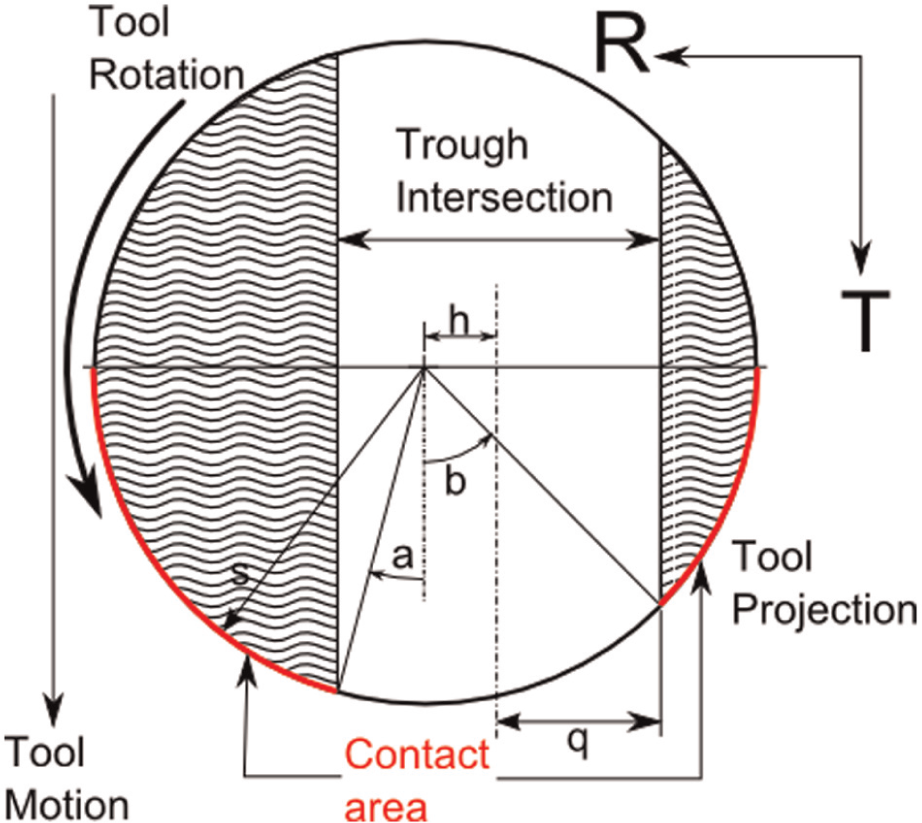
Top–down view of the tool at angle ψ, with the intersection of the previous toolpath shown.
For an arbitrary value of the angle ψ, the angles a and b are given by equation (3)
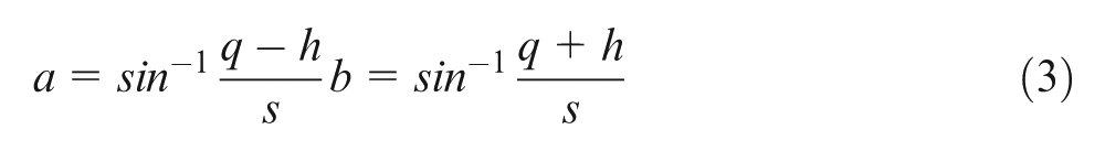
where q is the half-width of the intersecting trough, given by equation (4)
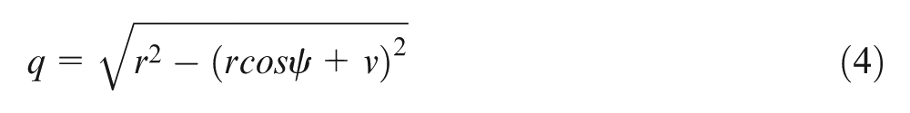
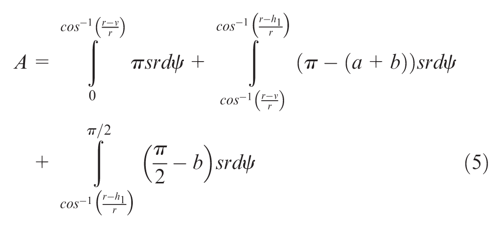
The area is then calculated for a point in the test according to equation (5). The three discrete components represent the area of the tool below the bottom of the trough, where the full half circle of the tool is swept; the area above the trough and below the bottom of the sheet, where contact occurs on both sides of the tool; and finally, the area above the bottom of the sheet, where contact only occurs on the outer side of the tool (Figure 6)
Creation of a contact patch model.
Results
The wall angle for each test is shown in Figure 7. At sheet failure, tool depths were recorded and used to calculate wall angle based on the computer-aided design (CAD) model and tool diameter. The current density at that point was calculated using the method in section “Modeling contact patch area.” While current was the independent variable for this test, current density is reported because it allows the results to be normalized for tool diameter, and allows comparison the EAF literature.
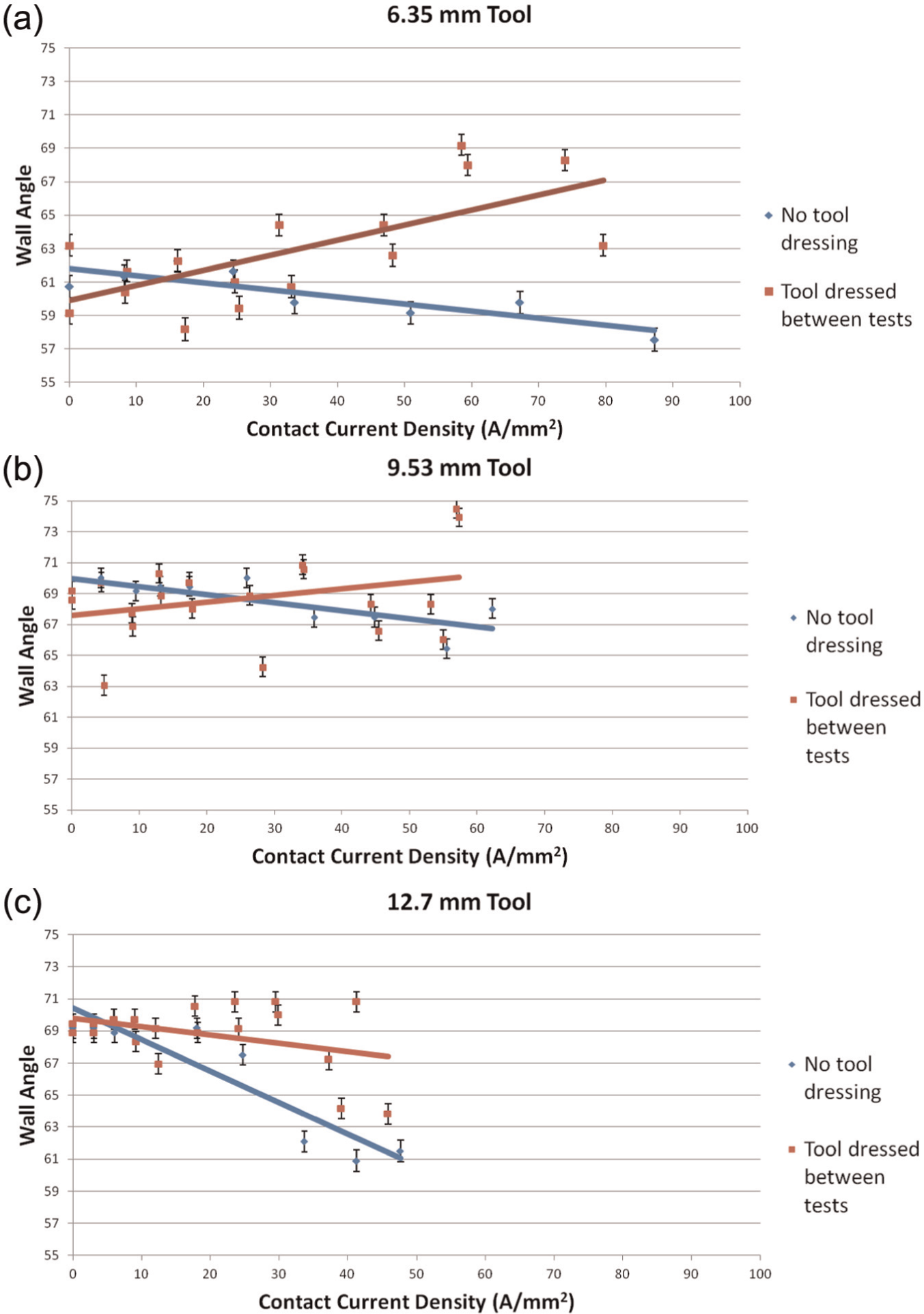
Wall angle as a function of current density at fracture for tool diameter (a) 6.35, (b) 9.53 and (c) 12.7 mm.
To ensure greater statistical significance, further tests were repeated with the 6.35-mm tool at 0 and 400 A (visible in Figure 3(a) as the highest peak for the tools that had been remachined between tests, near 60 A/mm2). The wall angles from these repeated tests are shown below. An additional set of tests was performed with cold air applied to the underside of the sheet to isolate the effects of the current from resistive heating.
To determine whether there is a significant increase in maximum wall angle attributable to sheet temperature, a pair of two-tailed t-tests were performed, each comparing the cooled and noncooled 400 A tests to the nonelectrified (0 A) baseline. Because two separate hypotheses are tested using the baseline data, a Bonferroni correction is applied to the confidence interval, requiring a P-value of 0.025 for rejection at 95% confidence.
Within the confidence bounds described above, a statistically significant difference was found between the noncooled 400-A tests (M = 69.1, standard deviation (SD) = 1.23) and the nonelectrified baseline (M = 66.3, SD = 1.41), t(8) = −3.25, p = 0.01. Between the cooled 400-A tests (M = 66.6, SD = 0.99) and the nonelectrified baseline tests, however, no significant difference was found, t(8) = −0.31, p = 0.76.
Surface roughness
Among the effects of current is the ability to change the surface roughness of the inside surface of the part. Figure 8 shows surface roughness RA values for the samples, as a function of current density.
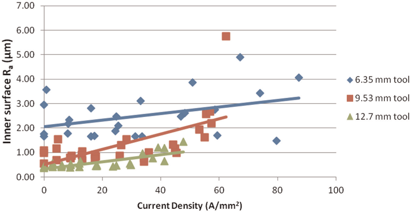
Surface roughness as a function of current density.
Constant current density
Two sets of tests were performed with constant current density, at 60 and 70 A/mm2, both with a 6.35-mm tool, allowing the results to be compared to the nonelectrified baseline. Three repetitions of each set point were carried out, and results were compared to the nonelectrified results tested in section “Modeling contact patch area.” Tests were performed in random order, and the tool was remachined between tests. Figure 9 shows the wall angle results for tests at 0, 60 and 70 A/mm2.
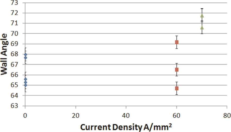
Wall angle as a function of current density for constant current density tests.
Discussion
During constant current tests, the best forming performance from both the 6.35- and 9.53-mm tools occurred when the current density was near 60 A/mm2 at fracture. In compression testing, Perkins et al. 11 found the threshold current density for 6061-T6511 to be between 54.6 and 60.8 A/mm2. Since for a constant current test, the current density decreases with increasing wall angle, this fracture point could be where the current density passed below the threshold value.
To determine whether there is indeed a threshold current density effect occurring, constant current density tests were compared to the nonelectrified tests using the same statistical method as in section “Results.” Using a two-tailed t-test, no significant difference was found between the 60-A/mm2 tests (M = 66.8, SD = 2.24) and nonelectrified baseline wall angle results, t(3) = 0.327, p = 0.76. A significant difference, however, was found between the 70-A/mm2 tests and the nonelectrified baseline results, t(6) = 6.87, p = 0.0004.
The greater variability of the 60-A/mm2 tests is also worth noting. The 60-A/mm2 tests had a standard deviation of 2.24, compared to 0.67 for the 70-A/mm2 tests. Because 60 A/mm2 lies within the threshold range published for this material, 11 it is possible that small variations within the current density magnitude result in the actual current density varying from one side to the other of some more exact threshold.
The simplifying assumptions within the contact patch model result in a simulated contact patch area that is smaller than the true area. The actual current density value is therefore slightly lower than the reported current density.
Tool fouling
As mentioned earlier, the first set of tests (blue points in Figure 7) showed lower wall angles and higher surface roughnesses than subsequent tests. For the first tests, the experiments were performed in ascending order of current magnitude with no remachining of the tool between tests. For subsequent tests, the surface of the tool was remachined between runs, and tests were done in random order to ensure that no tool effects were carried between tests.
The decreased performance from first tests where the tool was not remachined between tests suggests that the tool surface became degraded in some way from previous tests. Figure 10 shows the tip of the 6.35-mm tool after forming with applied current, showing material deposited on the surface of the tool. As a result of tool surface degradation, the increased friction between the tool and sheet appears to negate any positive effects from the applied current.
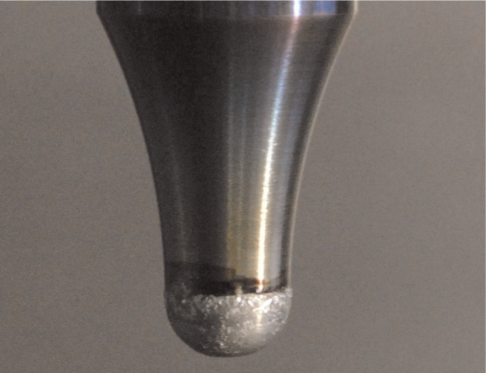
Tool fouling visible on the tip of the 6.35-mm tool after forming with current.
Current and surface roughness
In all tests with current, the roughness was raised above the nonelectrified baseline. Spalling of the surface also increases with current. To determine whether spalling is directly caused by current as opposed to lubricant breakdown due to heating, a test was performed with a constant wall angle, and current alternated between 0 and 500 A. The inside surface of the test is shown in Figure 11. Spalling at the surface occurred only in the test regions with current applied.
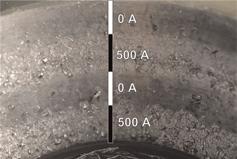
Surface of a constant wall angle cone with current varied between 0 and 500 A. Note the varying surface condition in the sections with and without applied current.
The increase in surface roughness could be indicative of increased tool friction. It is likely that the additional friction acts to negate the formability benefits, resulting in some optimal point for best forming and surface roughness performance. The surface roughness of parts formed with larger tools appeared to be less affected by the current than smaller tools; however, larger tools produced a lower initial wall angle.
Conclusions and future work
An apparatus was constructed to carry large currents to the rotating tool, and the maximum wall angle was tested for several current settings and tool diameters. Formability gains are seen at the same current density for different sizes of tools, suggesting that the current density is the most important factor and not current magnitude. The importance of current density agrees with EAF theory, as resistive heating in the sheet would be largely dictated by current magnitude. Tests with current switched from 0 to 500 A showed a very rapid response in inside surface texture, suggesting surface quality can correlate with current rather than pure thermal effects. Tests with cooling applied to the sheet were inconclusive in determining whether the process is independent of temperature.
Samples were formed at constant current density. The formability increase seen between 60 and 70 A/mm2 agrees with the published current threshold density for 6061-T6.
Future work in this area will investigate the suitability of this method for forming exotic materials such as titanium alloys. Direct experimental measurement of contact area will also be a continued focus, allowing the model above to be validated. Tool fouling will also be investigated, with the eventual goal of producing tool coatings and procedures that prevent tool fouling. The effect of current on surface friction (adhesion and abrasion) and on grain boundaries can also be studied.
Footnotes
Appendix 1
Declaration of conflicting interests
The authors declare that there is no conflict of interest.
Funding
This research was financially supported by AUTO21 (grant number C512 CAT) and NSERC (grant number 4960-2011).