
Abstract
Accurate simulation about the grinding temperature distribution helps to decrease the thermal damage and microcracks during the grinding process. In this article, the grinding heat transfer process of form grinding was analyzed and a temperature distribution model was derived in form grinding of 9Mn2V thread gauge. Considering the characteristics of form grinding, the temperature rise of the intersection region can be affected by two kinds of heat sources, and the impact between the two heat sources has been investigated. Also, the influence of the grinding depth on the temperature rise was analyzed. Depending on the analysis, an improved heat partition model has been derived, which is based on single-grain energy partition model. A series of experiments were carried out to investigate the grinding performance of 9Mn2V. The grinding force was obtained, the specific grinding energy was discussed, and the experimental temperature was measured by infrared imager. It is shown that the experiment results correspond well to the theoretical temperature calculated by the prediction model. This temperature model can be used to optimize the grinding conditions and the critical depth in form grinding of 9Mn2V thread gauge.
Keywords
Introduction
As special measuring tools in today’s manufacturing process of high-quality thread joints in oil well pipe, premium thread gauges have strict requirements on the material and machining process for its superior abrasion resistance, good dimension stability, and high machining precision. This article chooses one kind of premium thread gauge material, cold working die steel 9Mn2V, as the research objective. The hardness of 9Mn2V is higher than 62HRC and it has high wear resistance and preferable toughness, which makes it a perfect material for premium thread gauge. The heat treatment of 9Mn2V usually includes spheroidizing annealing, quenching, tempering, cryogenic treatment, and aging. 1
Grinding is one of the most accurate machining technologies for finishing high hardness materials.2 –5 Based on the characteristics of 9Mn2V thread gauge, form grinding has been applied to the manufacturing of this product. During the grinding process of 9Mn2V, high grinding temperature easily induces grinding burn and microcracks in the subsurface layer of the workpiece, 6 which is absolutely not acceptable for a product especially for a measuring tool. Therefore, it is necessary to develop a prediction model of the workpiece temperature distribution and improve the machining process of 9Mn2V thread gauge.
Grinding heat transfer has been studied for many years.7,8 Parente et al. 9 in 2010 studied the numerical computation method of the temperature field during grinding, by using the finite element method. The obtained results were then compared with the experimental results measured by the thermocouple. The article showed that it is possible to use a numerical method to obtain the temperature field, but no deduction steps and analytic equations were given. Skuratov et al. 10 in 2006 proposed a mathematical model of the workpiece temperature during the grinding process by using the Laplace and Fourier transforms and the Green’s function method. The article showed the evolution of the temperature in a workpiece during grinding, but the characteristics of the workpiece structure had not been considered. Rowe 11 proposed a more accurate model of conduction into the workpiece based on the moving inclined heat source instead of the sliding heat source for deep grinding. Also, a partition ratio model that included heat transfer to the workpiece, wheel, coolant and chips was created. Mamalis et al. 12 in 2002 proposed a finite element model to simulate the temperature fields during the precision grinding process and predict the heat-affected zones of the workpiece. The distribution of the temperature could be calculated successfully with the proposed model if the tangential force was known. Li et al. 13 investigated an inverse method for the heat transfer mechanism in the grinding zone and developed a quadratic curve heat flux distribution model which could decrease the error. Dong et al. 14 in 2015 investigated the grinding machinability and surface integrity of 9Mn2V under different heat treatment processes. The article showed the occurrence of grinding burn and grinding cracks changing with different grinding parameters during the grinding process of 9Mn2V. Morgan et al. 15 investigated the influences of the thermal properties of the grinding wheel on the energy partitioning in grinding in 1998. In this paper, the authors also compared the different thermal behaviors of cubic boron nitride (CBN) and alumina wheels in grinding, but they did not explain the reasons. Jin et al. 16 proposed a theoretical expression for burn threshold of high-carbon steel, which is based on the grinding heat transfer modeling. In this paper, all factors involved in heat partitioning, including grinding parameters, the thermal properties of the grinding wheel, coolant convection, and chip convection, were investigated.
Summarizing the previous literature of the grinding temperature, it is found that the research of heat transfer process in form grinding is little and mostly focuses on the finite element model and experimental research; the theoretical analysis of form grinding is rare. However, if the form grinding temperature exceeds austenite transformation temperature of 9Mn2V, the grinding burn and microcracks will emerge easily which will affect the thread gauge’s performance and shorten its service life seriously. Therefore, in order to decrease the defects and optimize the grinding depth, it is necessary to construct a prediction model to investigate the temperature distribution and heat transfer process during form grinding.
In this research, a theoretical model for workpiece temperature distribution in form grinding of premium thread gauge is derived, based on the following assumptions:
The workpiece is treated as a semi-infinite solid and the boundary condition is adiabatic boundary.
No wear occurs on the grinding wheel; meanwhile, the width of the heat source is equal to the axial feed rate fa .
The length of the heat source is equal to the actual contact length lc and longer than the theoretical contact length lg .
The grinding surface temperature reaches its peak value in a very short time, so that the moving velocity of the heat source is assumed as the feed rate of workpiece vw .
Based on the concepts above, the temperature distribution model of the form grinding contact zone is created, and the heat partition into the 9Mn2V workpiece is calculated. The accuracy of this model will then be determined through comparison with the actual form grinding temperature measured by the infrared imager.
Modeling of workpiece temperature in form grinding
Analysis of grinding contact zone
Many researches showed the differences between different kinds of heat distribution such as rectangular heat distribution, triangular heat distribution, isosceles triangular heat distribution, and trapezoidal heat distribution. However, due to the random distribution of the abrasive particles, the grinding thickness is not a constant value. Therefore, the potential error in the maximum temperature estimated by rectangular heat distribution is difficult to avoid. In this article, the triangular heat distribution was used to avoid significant errors.
Figure 1(a) shows the schematic diagram of form grinding of thread gauge. Different from the plane grinding conditions of surface AB, CD, and EF, the form grinding conditions of surface BC and DE are special due to the inclination angle β, as shown in Figure 1(b). In this article, temperature investigation was carried out only on AB and BC because AC and DF are symmetric and no heat is supposed to transfer from DF to AC. The theoretical grinding length of contact arc lg can be expressed as

where ae is the equivalent grinding depth and de is the equivalent diameter of the grinding wheel.
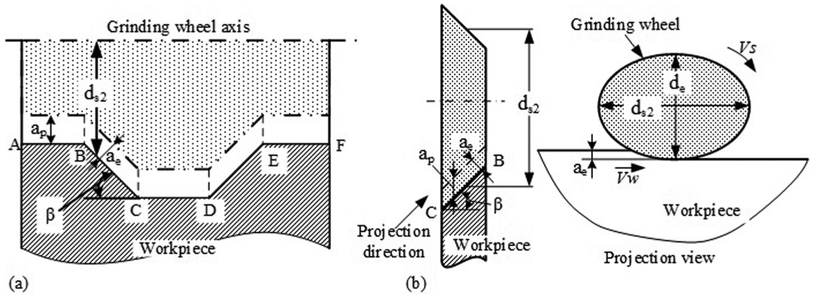
Schematic diagram of form grinding: (a) form grinding of the thread gauge and (b) inclined plane grinding on BC.
For form grinding of BC, as shown in Figure 1(b), ae and de can be expressed as
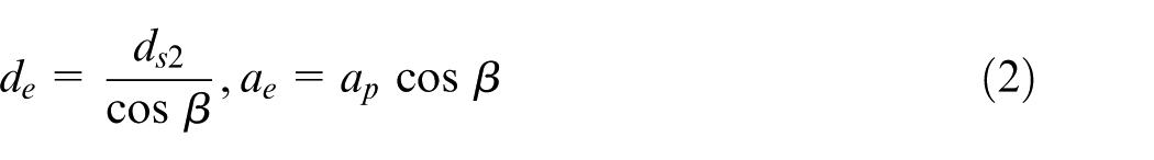
where ap is the grinding depth of the vertical direction and ds 2 is the median diameter of the grinding wheel.
In the real application for traditional grinding, in order to simplify the calculation, the actual length of the contact arc lc can be calculated as following 17

Modeling of temperature distribution on BC
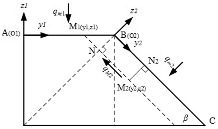
As Figure 2 shows, the contact surfaces during grinding are
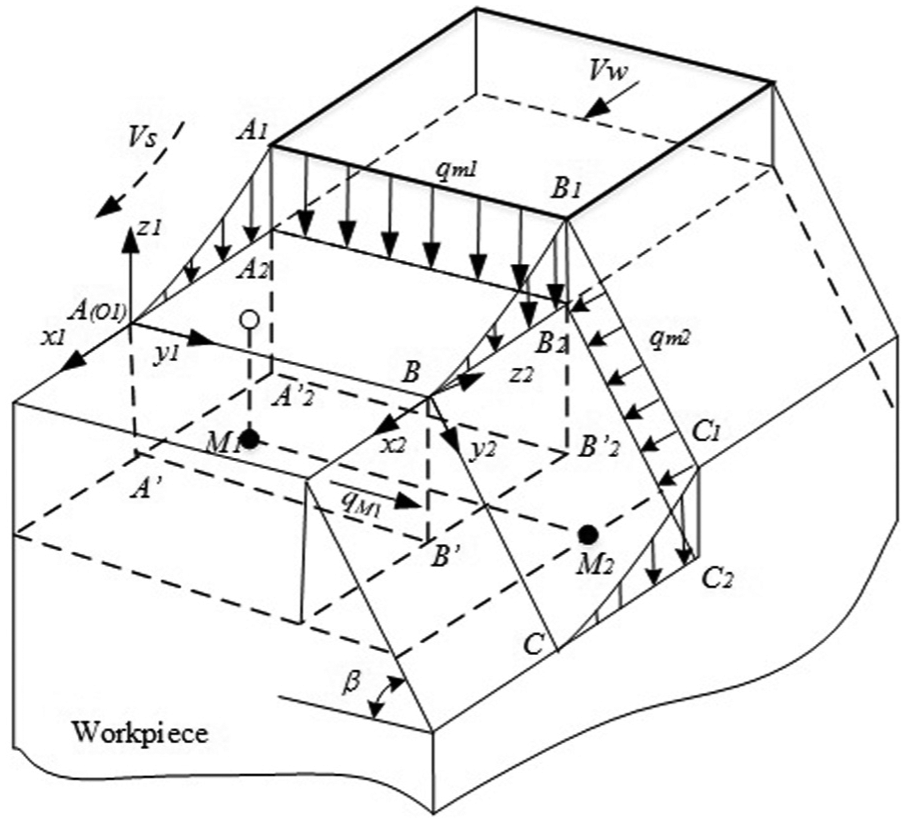
Location of points M 1 and M 2 when considering the temperature rise on BC.
Under the influence of heat fluxes
where
However, during the form grinding process, the heat flux
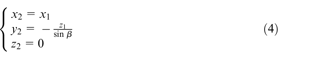
The heat transfer process from M
1 to M
2 can be simplified as one-dimensional heat conduction along the y1 direction. The
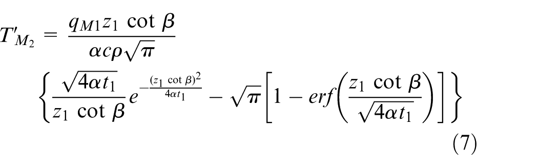
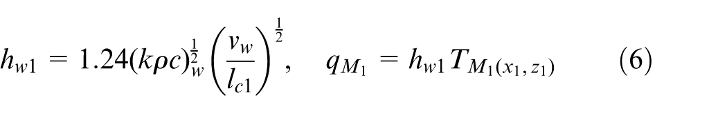
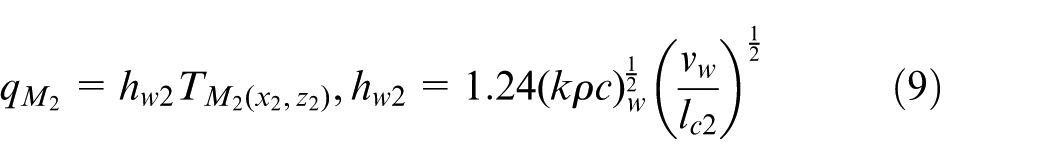
The heat flux

Meanwhile, the heat flux qM
2 transferred to M
2 from the grinding contact zone
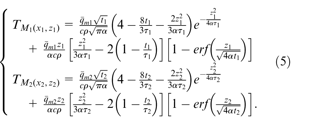
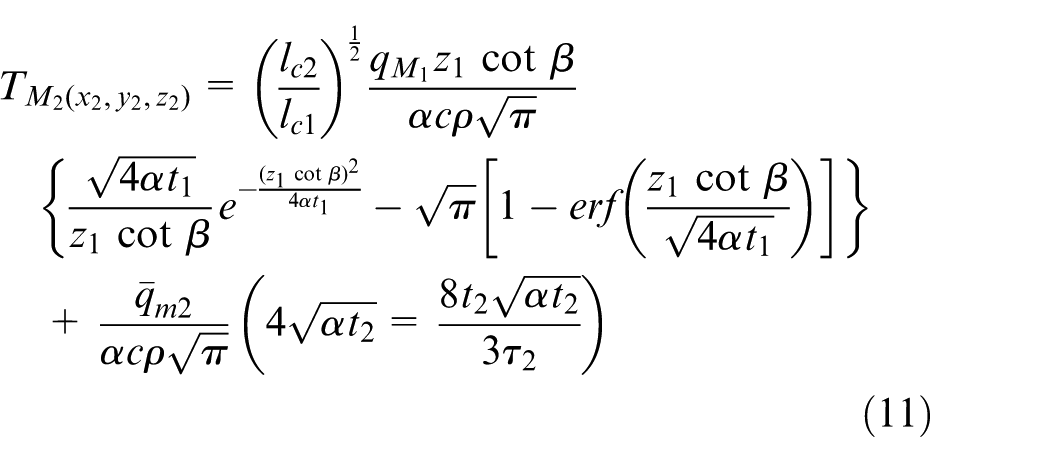
The total heat flux and the total temperature rise of M 2 are obtained
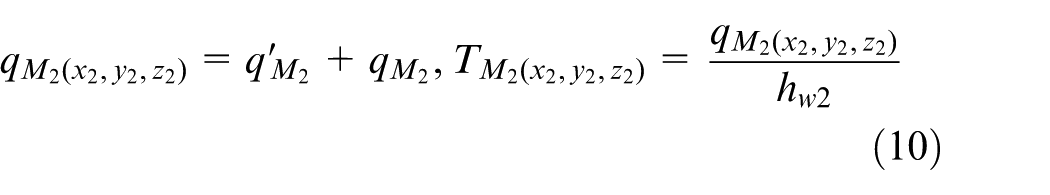
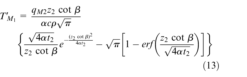
Substituting equations (5)–(9) into equation (10), the temperature rise of M 2 is illustrated as follows
Modeling of temperature distribution on AB
On the contrary, M
2 locates in the projection plane of contact surface
Location of points M 1 and M 2 when considering the temperature rise on AB.
As mentioned before, the influence of heat flux
The heat flux

The total heat flux and the total temperature rise of M 1 are obtained as

Determining heat partition into the workpiece
During the form grinding process, the total heat generation can be calculated through the following equation
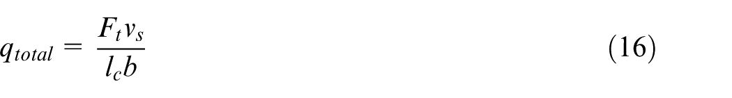
where Ft is the tangential grinding force and b is the grinding width.
The heat energy generated from the grinding process will transfer into the workpiece, abrasive grains in the wheel, and the grinding chips. In order to calculate the grinding temperatures, the fraction of the total heat entering the workpiece must be estimated at the first time. The heat partition into the workpiece is defined as Rw ; therefore, the heat flux into the workpiece qw could be calculated by multiplying the heat partition and the total heat generation
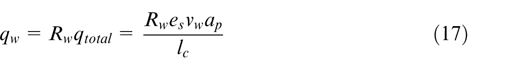
where es is the specific grinding energy.
Many different heat partition models were mentioned in previous literatures.18 –20 In this article, the calculation of heat partition is constituted by two models: one is applied to the grinding process of AB and the other is applied to the grinding process of BE, as shown in Figure 1(a). When grinding AB, an improved model based on single-grain energy partition model21 –23 is derived owing to its half-open grinding condition. Rw (AB) is estimated by subtracting the heat partition taken away by the chips Rch from the single-grain energy partition model. The specific calculation formula is shown as below
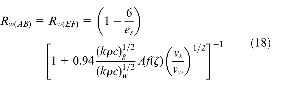
The subscript g stands for the grain and w for the workpiece; the calculation of
When grinding BE, because of the closed grinding condition, the heat partition model based on the grain–workpiece interface5,24 is used to estimate Rw (BE), which can be expressed as follows
In this article, to simplify the calculation of the heat generation, the specific grinding energy es in equation (17) is measured during a series of grinding experiments. The workpiece material used in this research is 9Mn2V, and the thermal conductivity k, density ρ, specific heat capacity c, and thermal diffusivity α of 9Mn2V are illustrated in Table 1. According to equations (18) and (19), Rw (AB) and Rw (BE) are estimated, as shown in Figure 4. The heat partition Rw (AB) is about 8%–9% lower than Rw (BE), because the heat dissipation conditions of plane AB are better than that of plane BE.
Physical and thermal properties of workpiece material.
Heat partition transfer into the workpiece (vs = 27 m/s, vw = 15 m/min): (a) grinding on surface AB or EF and (b) grinding on surface BE.
Experiment and discussion
Experiment setup
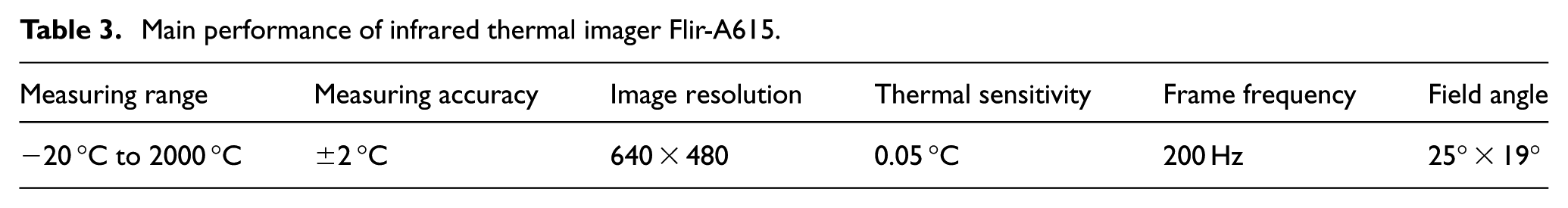
The experiments under different grinding conditions were conducted to investigate the accuracy of the temperature distribution model. The schematic diagram of the experiments is illustrated in Figure 5, and the detailed grinding conditions are listed in Table 2. The grinding experiments were carried out on KGS1020 precision grinding machine with a vitrified bonded aluminum oxide grinding wheel (3SG80KV) which was produced by sol–gel technique. The workpiece material is 9Mn2V, and the overall dimensions of the test-pieces are illustrated in Figure 5(a). Limited by the grinding technology, a transitional fillet (R = 0.2 mm) was formed on the intersecting line between AB and BC, as shown in Figure 5(a). Grinding force was measured with a Kistler9272 piezoelectric dynamometer, coupled to Kistler5070A multi-channel charge amplifier and computer data acquisition software. The grinding temperature was measured with a thermal infrared imager Flir-A615, and the main performance of Flir-A615 is listed in Table 3.
Grinding conditions.
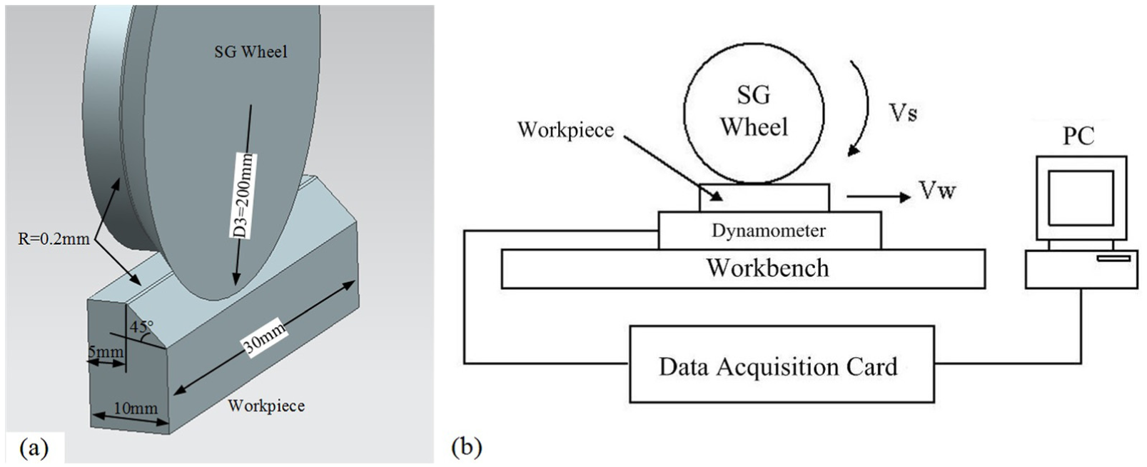
Experiment setup: (a) schematic of grinding wheel and workpiece and (b) panorama of experimental setup.
Main performance of infrared thermal imager Flir-A615.
Results and discussion
In this section, the experimental temperature is used to compare with the theoretical temperature results. First of all, the grinding tangential force was measured and then the specific grinding energy was calculated as shown in Figure 6.
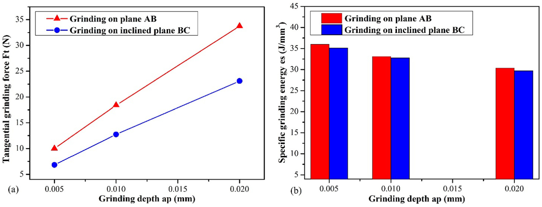
Measured tangential grinding force and specific energy: (a) tangential grinding force and (b) specific grinding energy.
Based on the calculated specific grinding energy, heat partition calculated in section “Determining heat partition into the workpiece,” and the temperature prediction model proposed in section “Modeling of workpiece temperature in form grinding,” the theoretical temperature distribution of the grinding contact zone is presented in Figure 7. Figure 7(a) shows the theoretical temperature distribution of the median line of the grinding contact zone, which has the highest temperature during the grinding process. It is clear that under the interaction effect of two heat sources
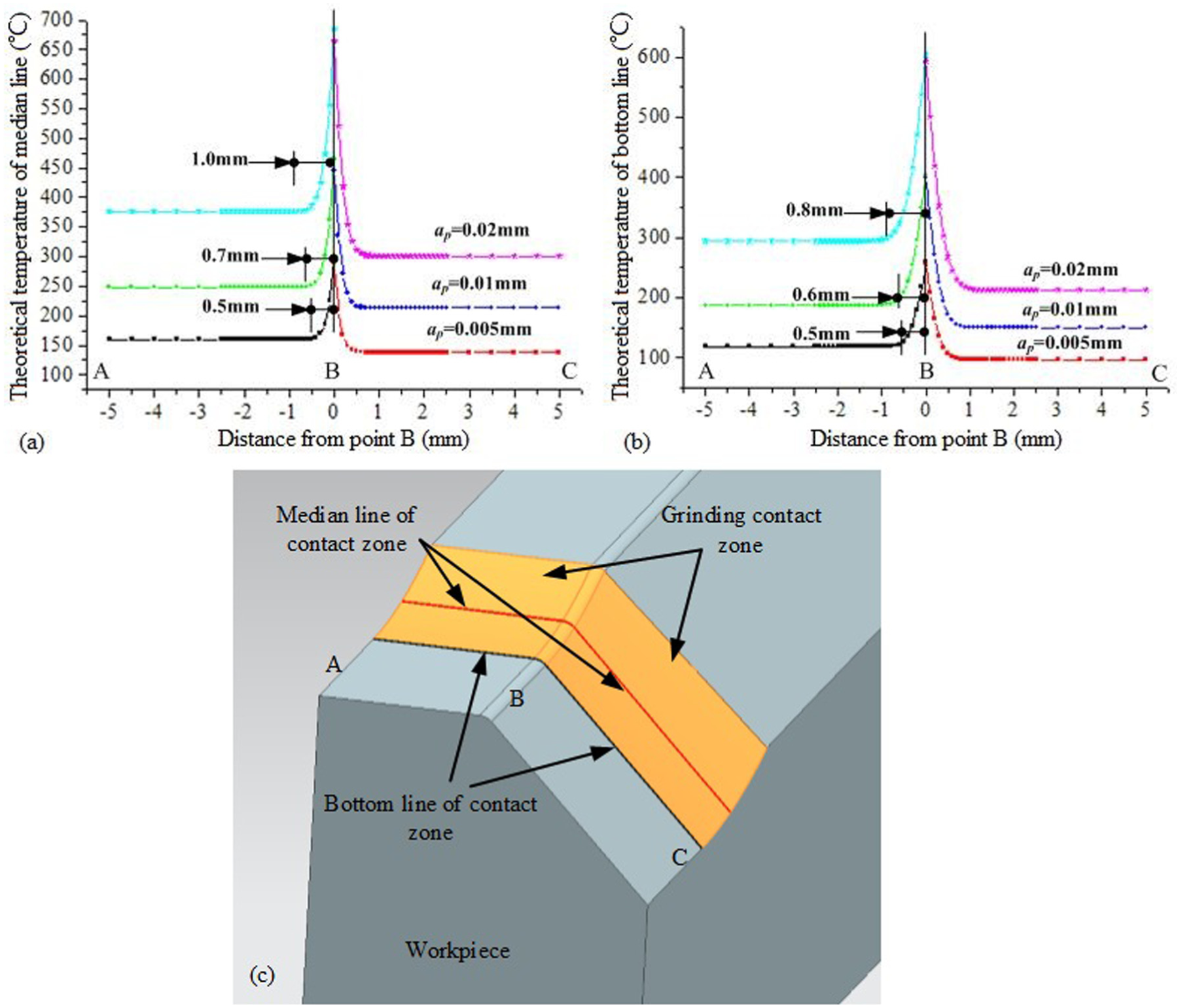
Theoretical temperature of form grinding: (a) temperature distribution of median line, (b) temperature distribution of bottom line, and (c) position of median line and bottom line in contact zone.
The peak temperature and the width of high-temperature zone.
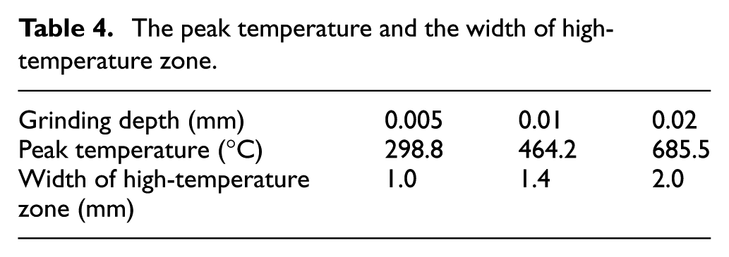
As Table 4 shows, although the temperature rise caused by grinding AB or BC alone is lower than 380 °C, the peak temperature of the intersection area exceeds 685 °C, which is close to the austenitic transformation temperature. It shows that the temperature rise in form grinding is quite larger than traditional grinding. In this situation, the critical depth in form grinding of thread gauge is 0.02 mm. Otherwise the highest temperature will exceed the austenitic transformation temperature, which will cause the secondary hardening problems and serious grinding burn.
Figure 7(b) shows the theoretical temperature distribution of the bottom line of the grinding contact zone. The mutation region of the temperature also exists, but the maximum temperature decreases a little and the width of high-temperature zone becomes smaller, compared with the median line.
Figure 8 shows the maximum temperature of the grinding contact zone measured by infrared thermal imager at different grinding depths. And Figure 9 shows the comparative results of the experimental temperature and theoretical temperature. It is clear that the measured temperature locates in the temperature interval of three consecutive points (B′, B″, and
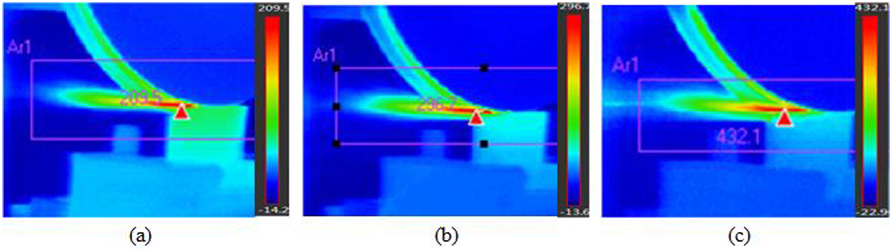
The maximum temperature of grinding contact zone measured with infrared thermal imager: (a) grinding depth ap = 0.005 mm, (b) grinding depth ap = 0.01 mm, and (c) grinding depth ap = 0.02 mm.
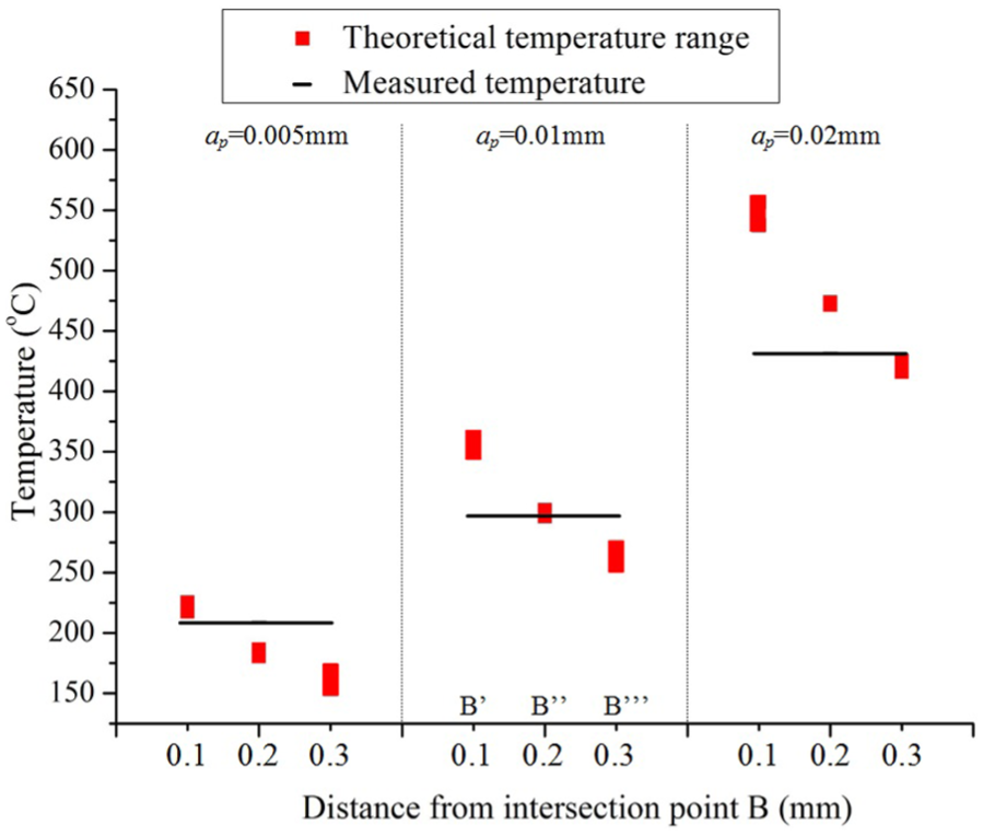
The experimental temperature and theoretical temperature.
Conclusion
In this article, the grinding-specific energy and temperature distribution in form grinding of 9Mn2V thread gauge are discussed under different conditions. A temperature prediction model is proposed to simulate the temperature distribution in form grinding. The following conclusions are obtained:
The heat partition coefficients of 9Mn2V workpiece are discussed by using the improved heat model. It is found that the heat partition into grinding workpiece reaches up to 76.5% for plane AB and 84.4% for plane BC at ap = 0.005 mm.
The prediction results of the proposed temperature model correspond well to the experimental temperature measured with infrared thermal imager. The comparisons verify that the theoretical model is available to predict the temperature distribution in form grinding under different conditions.
The temperature of point B is affected by the grinding process of both planes AB and BC, and the peak temperature is almost 85% higher than that of point A and 120% higher than that of point C. The width of the high-temperature zone increases from 0.5 to 1 mm with an increase in the grinding depth from 0.005 to 0.02 mm.
The theoretical temperature of the workpiece increases with the increase in the grinding depth. As the grinding depth increases from 0.005 to 0.02 mm, the peak temperature increases about 129%. In order to avoid the thermal damage and microcracks of the workpiece, the form grinding depth of 9Mn2V thread gauge must be smaller than 0.02 mm.
Footnotes
Appendix 1
Declaration of conflicting interests
The author(s) declared no potential conflicts of interest with respect to the research, authorship, and/or publication of this article.
Funding
The author(s) disclosed receipt of the following financial support for the research, authorship, and/or publication of this article: The work was supported by the National Natural Science Foundation of China (No. 51405290).