
Abstract
Friction stir welding is a solid-state welding technique for joining metals such as aluminum alloys quickly and reliably. This article presents a design of experiments approach (central composite face–centered factorial design) for predicting and optimizing the process parameters of dissimilar friction stir welded AA6351–AA5083. Three weld parameters that influence weld quality were considered, namely, tool shoulder profile (flat grooved, partial impeller and full impeller), rotational speed and welding speed. Experimental results detailing the variation of the ultimate tensile strength as a function of the friction stir welding process parameters are presented and analyzed. An empirical model that relates the friction stir welding process parameters and the ultimate tensile strength was obtained by utilizing a design of experiments technique. The models developed were validated by an analysis of variance. In general, the full impeller shoulder profile displayed the best mechanical properties when compared to the other profiles. Electron backscatter diffraction maps were used to correlate the metallurgical properties of the dissimilar joints with the joint mechanical properties as obtained experimentally and subsequently modeled. The optimal friction stir welding process parameters, to maximize ultimate tensile strength, are identified and reported.
Introduction
The aluminum alloys AA6351 (heat treatable) and AA5083 (nonheat treatable) are extensively used in aviation, shipbuilding, automotive and transport industries due to properties such as low density, good strength and corrosion resistance. Dissimilar welding of these two alloys with conventional fusion welding technique is challenging due to the difficulties associated with the lack of a suitable filler metal and the difference in solidification due to the variation in mechanical, thermal and chemical properties. The melting and re-solidification of the fusion zone during conventional fusion welding produce brittle phases that have a detrimental effect on the hardness, strength and ductility of the joint. These problems may be largely overcome by a solid-state joining technique such as friction stir welding (FSW) that makes joining of dissimilar alloys a viable proposition. The joint is produced by plastically deforming material adjacent to the joint path using a rotating tool with a protruding central pin. The FSW joint has low distortion and residual stress because it does not melt and recast as in conventional fusion welds; hence, a reliable dissimilar joint is produced.1–3 The development of this technology, especially with regard to joining of dissimilar metals, is important where high-quality joints are required in marine, aviation and structural applications.4,5
The FSW process parameters including tool geometry have a significant effect on the joint quality. The major functions of the tool (and therefore influenced by the tool geometry) are to generate heat, plasticize the material, direct the flow of plasticized material and prevent defect formation. Scialpi et al. 6 reported that a tool shoulder with both a cavity and a fillet produces better results than shoulders with a scroll and fillet or a fillet only when FSW AA6082 alloy. Elangovan and Balasubramanian 7 pointed out that the shoulder-to-pin diameter ratio has a significant effect on the mechanical and metallurgical properties of the joint when FSW AA6061 alloys. Hattingh et al. 8 reported that optimization of the tool design can lead to weld joints with 97% the tensile strength of the base plate. Leal et al. 9 reported that during FSW of dissimilar aluminum alloys, the pin-driven flow is predominant when a conical cavity shoulder is used; however, the interaction between the pin and shoulder-driven flow is predominant when a grooved shoulder is used. Schmidt et al. 10 developed and used an analytical model to report that most of the heat is generated by the shoulder, and only about 14% is generated by the pin. Leal et al. 11 investigated the effect of the shoulder cavity and process parameters on the microstructure and mechanical properties of thin copper sheets. They concluded that the tool rotational speed had a more pronounced effect on the tensile properties than welding speed and shoulder profile. Aval et al. 12 investigated the effect of tool geometry on the mechanical and microstructural behavior during dissimilar FSW of AA5086–AA6061. They reported that the tool with a concave shoulder and a conical pin with three grooves produced a homogeneous weld zone due to increased heat input. Mehta et al. 13 investigated FSW of AA7075-T6 alloy. They concluded that the heat generation increases with increasing shoulder diameter and that the optimum diameter is a function of the tool’s rotational speed. Gadakh Vijay and Adepu 14 developed welding window for FSW of AA6061-T6 alloys and reported that shoulder-to-pin diameter ratio with value 3 showed better mechanical properties.
Peel et al. 15 studied FSW of AA5083 and AA6082 and reported that tool rotational speed had a more pronounced effect on heat generation than welding speed. Steuwer et al. 16 studied the effect of tool rotational speed and welding speed for FSW of AA5083 and AA6082. They reported that the tool rotational speed is an important process parameter to optimize the residual stress. Cavaliere et al. 17 achieved maximum ultimate tensile strength (UTS) for FSW of AA6056 at a rotational speed of 1000 r/min and welding speed of 80 mm/min. They also observed very fine and equiaxed grains at the weld zone when compared to the base metal. Liu and Ma 18 stated that the tensile strength of FSW of 6-mm-thick AA6061-T651 is strongly dependent on the welding speed. Biswas et al. 19 reported that mechanical properties depended on the ratio of the tool rotation speed to the welding speed. Palanivel et al. 20 concluded that tool rotational speed and tool pin profile have a significant effect on the tensile behavior of dissimilar aluminum alloys.
FSW process parameters such as shoulder profile, tool rotational speed and welding speed largely determine the mechanical properties of the joints. In order to increase the efficiency of the FSW process, the mechanical properties of joints must be optimized. Therefore, it is important to determine the welding parameters at which the mechanical properties reach their optimum. Design of experiments (DOE) is one such technique that may be used to model and optimize the FSW process. A series of investigations have been conducted where FSW of aluminum and steel alloys were modeled using DOE.21–26 Balaji and Mahapatra 21 used DOE approach to determine the influential control factors for the optimization of friction stir welded AA2219 alloys for aerospace applications. Rajakumar et al. 22 optimized the process parameter to maximize the UTS friction stir welded AA7075-T6 aluminum alloy joints. Saeidi et al. 23 developed a mathematical model using DOE to demonstrate a relationship between the FSW parameters and the UTS of the dissimilar AA5083 and AA7075 joints. Dinaharan and Murugan 24 optimized FSW process parameter to maximize tensile strength of AA6061/ZrB2 in situ composites. In this investigation, an attempt is made to predict and optimize FSW process parameters to attain the maximum UTS for FSW of dissimilar aluminum alloys.
Experimental work
The literature identifies tool shoulder profile, tool rotational speed and welding speed as the most significant FSW process parameters when considering the joint mechanical properties. The FSW tools for the current investigation were fabricated from a high-carbon, high-chromium steel that is oil hardened. The shoulder profiles investigated are partial impeller (PI), full impeller (FI) and flat grooved (FS; see Figure 1). The tools were fabricated by computer numerical control (CNC) turning and wire electrical discharge machining. The basic dimensions of the tools were shoulder diameter of 18 mm, pin diameter of 6 mm and the pin length of 5.7 mm. The profiles in the shoulder are 2 mm in depth for all three tools. The chemical and mechanical properties of AA6351 and AA5083 are presented in Tables 1 and 2, respectively (material certificate). Plates of size 100 mm × 50 mm × 6 mm were prepared from the rolled plates. The plates were mounted on the fixture as shown in Figure 2. The plates were affixed such that AA6351 corresponded to the advancing side and AA5083 to the retracting side, respectively. Trial experiments were conducted to identify the minimum and maximum limits for the process parameters. This was carried out by varying each parameter individually while keeping the rest constant. The limits of each process parameter were determined based on the weld having a smooth appearance as shown in Figure 3 without any visible defects. The maximum and minimum limits for different levels of the identified process parameters are presented in Table 3. The experimental design matrix utilized in this work is presented in Table 4. This matrix is based on a central composite face–centered factorial design consisted of a full factorial 23 = 8, plus six center points and six star points. This implies 20 experiments and therefore allows the estimation of the linear, quadratic and two-way interactive effects of a process parameter on the tensile properties. 25 All process parameters at the intermediate level (0) constitute the center points, and the combinations of each of the process parameters at either their minimum (−1) level or maximum (+1) level with the other two parameters at the intermediate levels constitute the star points. FSW then commenced on a machine according to the DOE matrix as outlined in Table 4. Five tensile test samples were prepared from each trial perpendicular to the weld joint as per ASTM E8-04. Testing was conducted using a computerized universal testing machine (HITECH TUE-C-1000), and the average values are presented in Table 4. Photograph of some of the tensile-tested specimens are presented in Figure 4. To carry out a metallurgical investigation, specimens were cut from the joint perpendicular to the weld path. As per standard metallographic technique, the specimens were polished and etched with Keller’s etchant. The macrostructure was observed using a digital optical scanner, and the results were presented in Table 5. Microstructure including grain size of the FSW samples was observed by electron backscatter diffraction (EBSD).
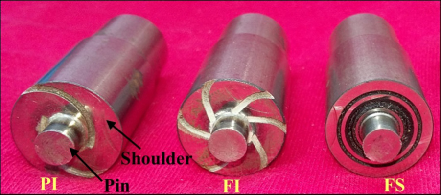
Fabricated tool for FSW with partial impeller (PI), full impeller (FI) and flat grooved (FS) shoulder profiles.
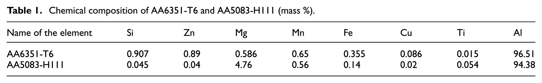
Chemical composition of AA6351-T6 and AA5083-H111 (mass %).
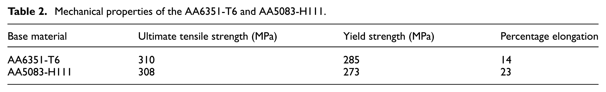
Mechanical properties of the AA6351-T6 and AA5083-H111.
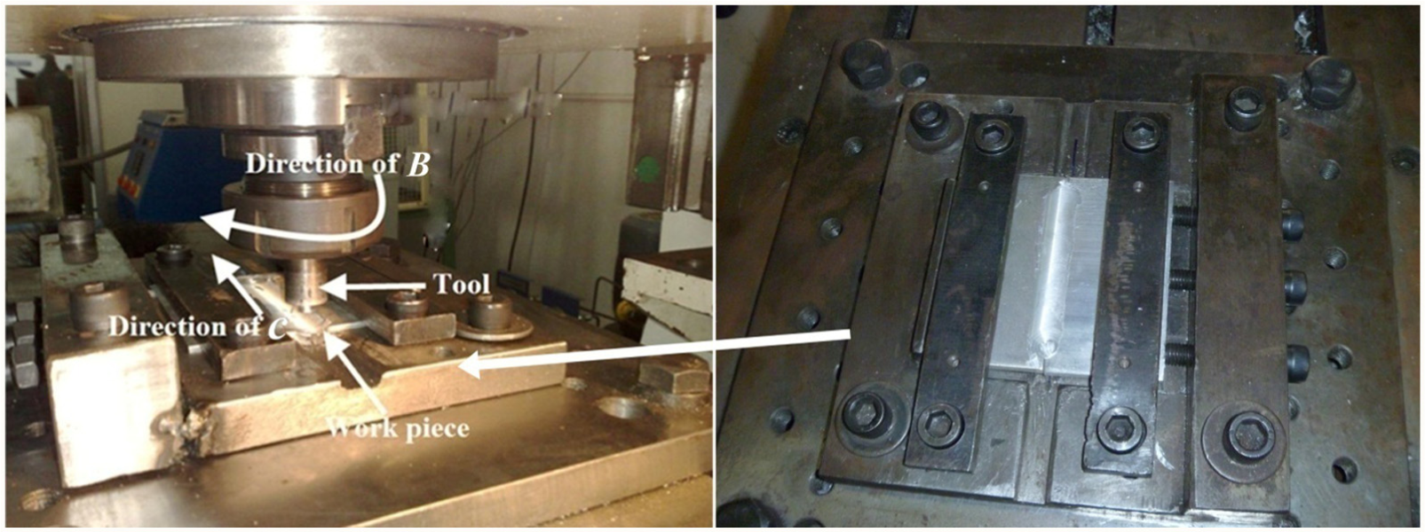
Experimental setup.
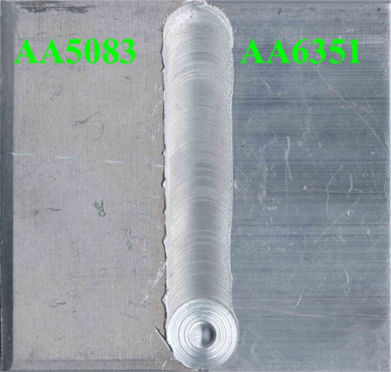
Crown appearance of the dissimilar FSW joint without any visible defects.
Process parameters with levels.
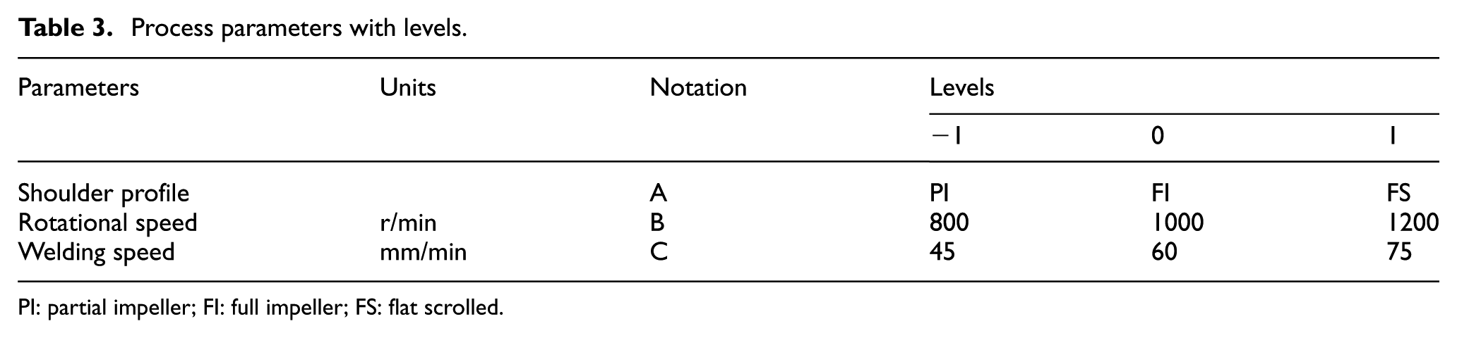
PI: partial impeller; FI: full impeller; FS: flat scrolled.
Design of experiments matrix for the FSW process parameters along with the experimental results obtained and the subsequent predicted values (UTS).
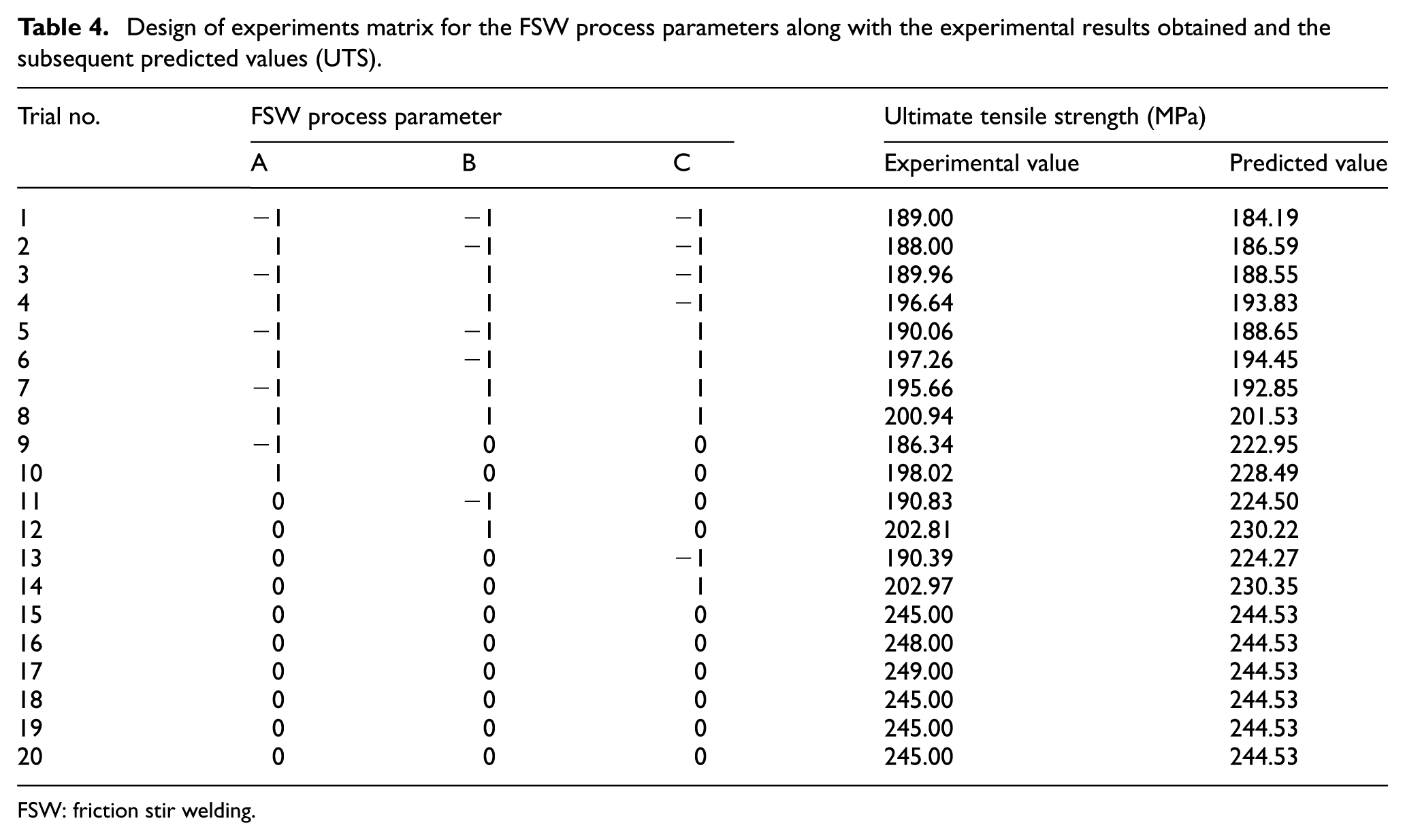
FSW: friction stir welding.
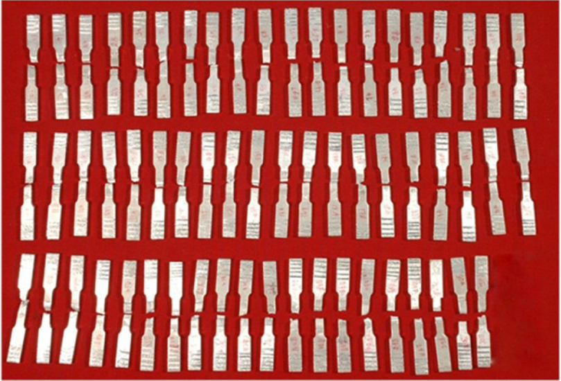
Photograph sample of tensile specimen after tensile test.
Effect of process parameters on macrostructure of the dissimilar FSW joints.
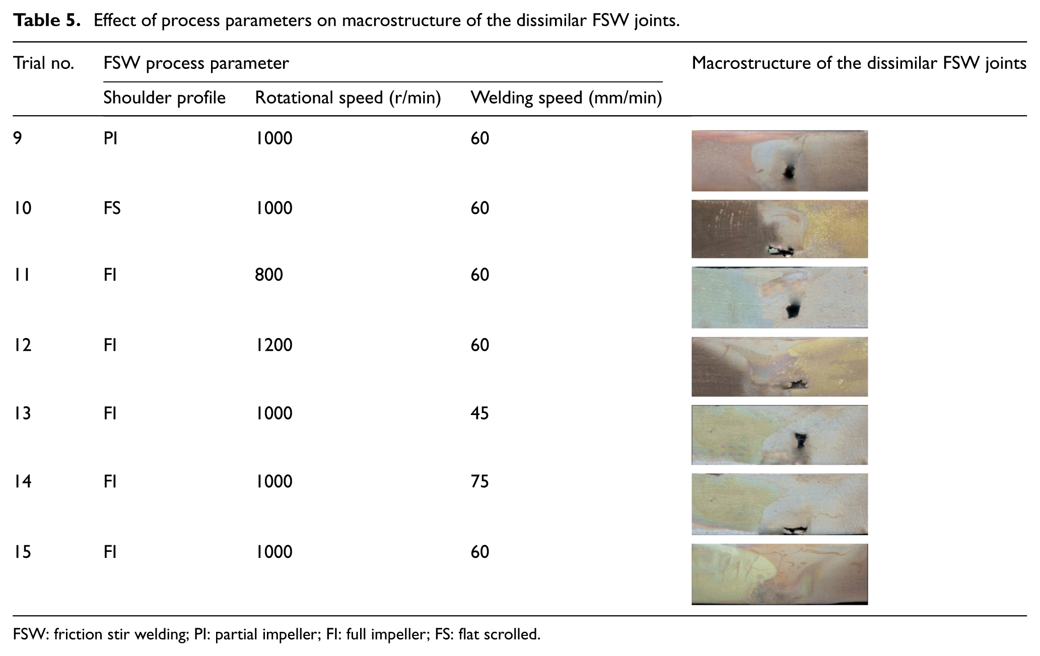
FSW: friction stir welding; PI: partial impeller; FI: full impeller; FS: flat scrolled.
Empirical modeling
The UTS of dissimilar friction stir joints are a function of the shoulder profile (A), tool rotational speed (B) and welding speed (C) which is expressed as
where Y is the response (UTS), A is the shoulder profile, B is the tool rotational speed (r/min) and C is the welding speed (mm/min)
A polynomial that relates the response (UTS) with the input parameters (FSW process parameters) can be expressed as follows
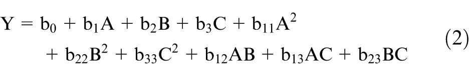
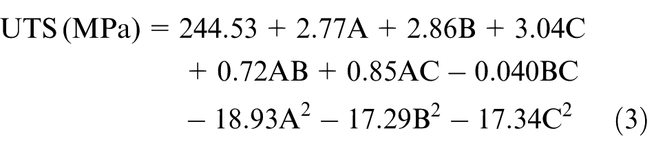
where b0 is the free term of the regression equation; b1, b2 and b3 are linear terms; b11, b22 and b33 are quadratic terms; and b12, b13 and b23 are the interaction terms. The various coefficients were obtained by regression analysis with the help of Design-Expert 8.0.7.1 software. The final empirical model as obtained from the analysis as alluded to above is presented as follows (in coded form)
Adequacy check for the developed model
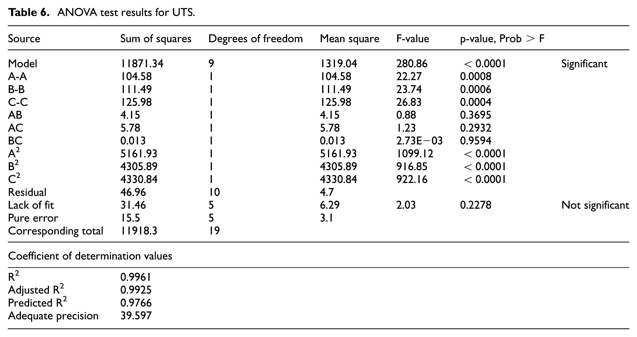
The ability of the model to adequately describe the experimental results is assessed by an analysis of variance (ANOVA) for which the results are tabulated in Table 6. A model F-value of 280.86 implies that the model is significant. There is only a 0.01% probability that a model of large F-value could occur due to noise. The values of “Prob > F” < 0.0500 indicate that model terms are significant. In this case, A, B, C, A2, B2 and C2 are significant model terms. The values >0.1000 indicate that the model terms are not significant. The “Lack of Fit F-value” of 2.03 implies that the lack of fit is not significant relative to the absolute error. A nonsignificant lack of fit is desirable.25,26 The predicted R2 of 0.9961 is in reasonable agreement with the adjusted R2 of 0.9925. Adequate precision implies an appropriate signal-to-noise ratio of >4. For this model, the ratio of 39.597 indicates an adequate signal-to-noise ratio. The experimental and predicted values are scattered near the 45° line (Figure 5) which indicates an excellent fit. Three conformity weld runs are made using different combinations of parameter other than those used in the design matrix. The results obtained are quite satisfactory, and the details are presented in Table 7.
ANOVA test results for UTS.
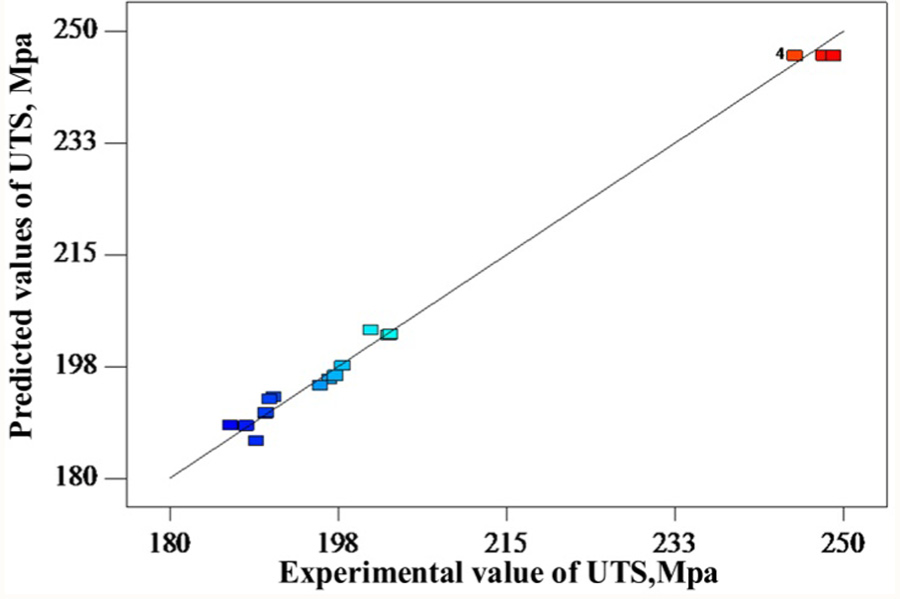
Scatter of experimental values versus predicted values for UTS.
Results of conformity test.
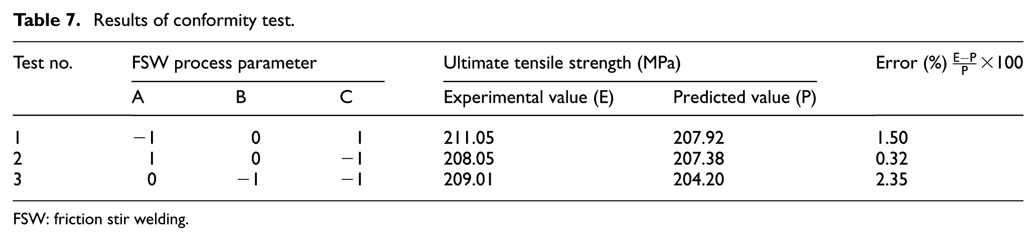
FSW: friction stir welding.
Effect of FSW process parameters
The effect of various process parameters on the UTS of friction stir welded dissimilar aluminum joints involving AA6351 and AA5083 as obtained experimentally and then modeled empirically is presented in Figures 6–8.
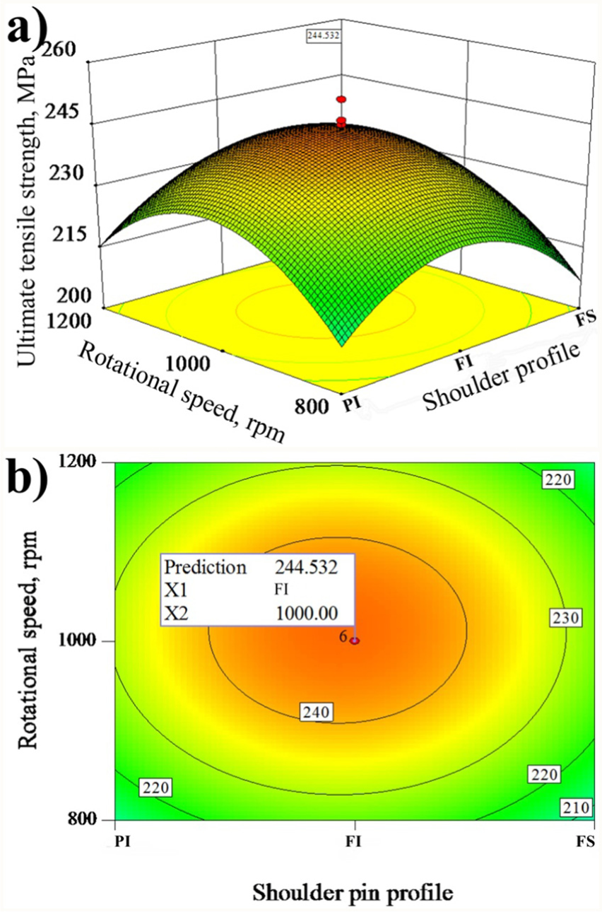
(a) Response graph of shoulder pin profile and rotational speed on UTS and (b) contour plot of shoulder pin profile (X1) and rotational speed (X2).
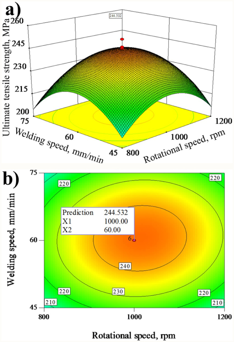
(a) Response graph of rotational speed and welding speed on UTS and (b) contour plot of rotational speed (X1) and welding speed (X2).
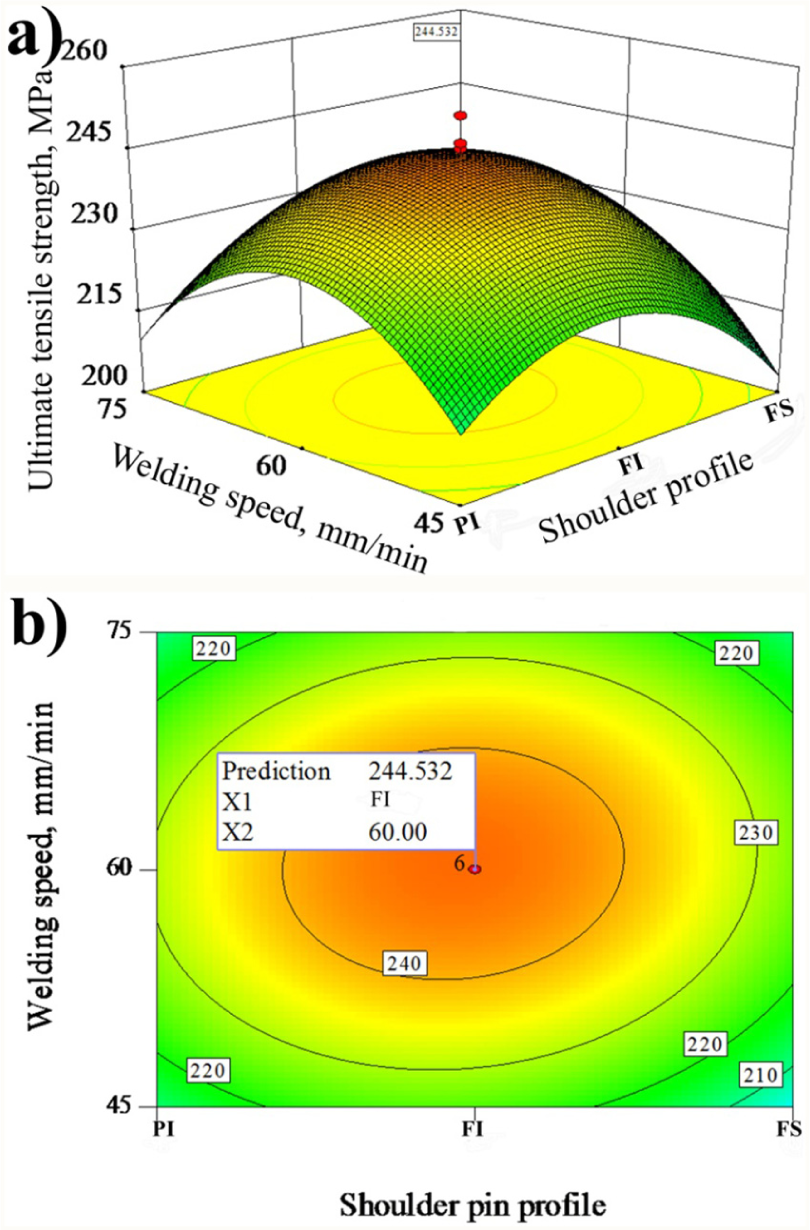
(a) Response graph of shoulder pin profile and welding speed on UTS and (b) contour plot of shoulder pin profile (X1) and welding speed (X2).
The effect of the various process parameters investigated on the macrostructure of the dissimilar joints is presented in Table 5. It is evident from the response surface graphs, as presented in Figures 6(a) and 7(a), that at the lower rotational speeds (800 r/min), the UTS of the FSW joint is lower. As the rotational speed is increased from 800 r/min, the UTS increases to attain a maximum value at 1000 r/min. When the rotational speed is increased beyond 1000 r/min, the UTS of the joint decreases. A lower rotational speed effectively reduces the surface area of the weld zone and affects the associated temperature distribution. A lower rotational speed produces less heat which leads to a lack of stirring and, therefore, produces joints with significant defects (Table 5, trial 11) and, therefore, reduced strength. An increase in rotational speed is associated with an increase in heat input. Excessive heat input disrupts the flow behavior of the plasticized material and produces an excess of stirred material on the surface which leads to defects forming (Table 5, trial 12) in the weld zone.
The effect of welding speed on the UTS of the friction stir welded joints is presented in Figures 7(a) and 8(a). It reveals that a low welding speed (45 mm/min) corresponds to lower UTS. With an increase in welding speed, the UTS also increases to attain a maximum at the intermediate speed of 60 mm/min. A further increase beyond this speed leads to a reduction in the UTS of the joint. As the welding speed is high, the joint is exposed for less time; this causes insufficient plastic flow of material with insufficient heat input which causes defects (Table 5, trial 14). High welding speeds are associated with lower heat input, which results in a more rapid cooling rate of the weld joints that produces joint defects (Table 5, trial 14) that may have a negative effect on the UTS.
The response surface graph illustrated in Figures 6(a) and 8(a) indicates the influence of the shoulder profile on UTS of FSW joints. The FS profile shows a low value of UTS, PI shows a slightly improved value of UTS and FI shows a maximum value of UTS on weld joints. During FSW, the flow behavior of material depends on the degree of plasticization beneath the tool which is determined by heat generation, physical properties of the materials and the capacity of the tool to promote the deformed material toward the root of the weld. 27 The frictional heat generated at the interface between the tool and the material is dependent on the shoulder profile, rotational speed and welding speed. The function of the shoulder profile is to produce heat and perform as an escape volume of the material displaced by the pin, therefore enhancing the extrusion and consolidation of the material during welding. The shoulder promotes the transport of material at the top surface, from the retreating to the advancing side, and pushes it downward within the pin diameter. In this case, the shoulder profile having FI is sufficient to do that job, not allowing material to escape for the formation of defects due to its multiple impeller region compared to PI and FS tool shoulder. However, FI shoulder profile also fails to generate optimum heat to ensure proper plasticization of the material, leaving the end of the pin too far from the anvil at lowest and highest ranges of welding speed and rotational speed. The defect formation in the root of the weld depends on the material flow. This defect prevents to establish the plastic deformation and coalescence of the materials. The no defect (Table 5, trial 15) in welds suggests that the volume under the shoulder is sufficient to constrain the material displaced by the pin and shoulder. Since the welds made by the FI shoulder with 1000 r/min and 60 mm/min are free of defects, it is possible to conclude that optimum heat input associated with those ranges allowed adequate material flow close to the root of the weld.
Figure 9 presents EBSD maps of the base materials AA6351 and AA5083 displaying grain sizes of 14.69 and 6.47 µm, respectively. EBSD maps of the weld zones of the dissimilar joints are presented in Figures 10 and 11. The grain size in the weld zone is essentially associated with the heat generated during the welding process. The heat available is a function of the tool geometry and process parameters. 27 Figure 10 clearly shows that for an intermediate rotational and welding speed (1000 r/min and 60 mm/min), the FI shoulder profile displayed the smallest grain size. The weld zone grain sizes for the FI, PI and FS shoulder profiles are 3.8, 4.5 and 5.6 µm, respectively. The weld joint produced by the FI tool shoulder displayed the finest grains (Figure 10(a)) when compared to the other tool profiles irrespective of the tool rotational and welding speed. These finer grains subsequently displayed the highest UTS.
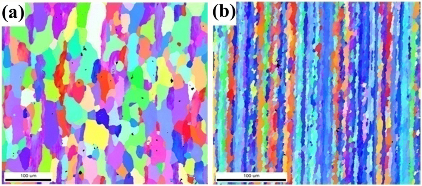
EBSD images of base materials: (a) AA6351 and (b) AA5083.
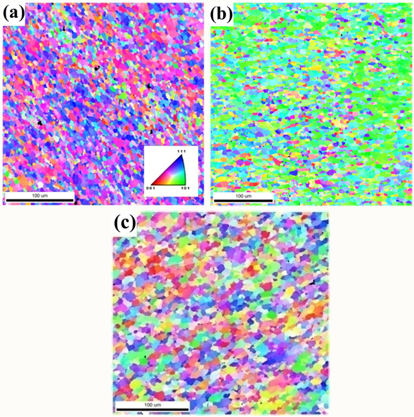
EBSD images of the weld zone for the different shoulder profiles with rotational speed of 1000 r/min and welding speed of 60 mm/min: (a) full impeller, (b) partial impeller and (c) flat grooved.
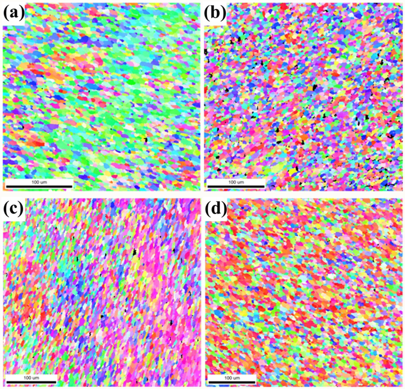
EBSD images of the weld zone using full impeller shoulder profile with a combination of rotational speed and welding speed: (a) 900 r/min and 45 mm/min, (b) 1200 r/min and 60 mm/min, (c) 900 r/min and 75 mm/min and (d) 800 r/min and 60 mm/min.
The FI shoulder profile displayed courser grain sizes for both extremes of rotational speed (compare Figures 10(a) and 11(b) and (d)) and welding speed (compare Figures 10(a) and 11(a) and (c)). The grain sizes obtained being 4.6 and 5 µm at 45 and 75 mm/min, respectively, and 5.3 and 4.45 µm at 800 and 1200 r/min. Grain formation and growth occur in the weld zone because of dynamic recrystallization. The finer grain sizes in the weld zone observed for the FI shoulder profile at a tool rotational speed of 1000 r/min and welding speed of 60 mm/min occur because of a complex interaction of its enhanced stirring ability and the subsequent heat generation and dissipation in the heat affected zone that influences the recrystallization and subsequent grain growth. Recrystallization commences at lower temperatures depending on the extent of the deformation. The subsequent grain growth is then a function of the available heat (temperature). The FI shoulder profile along with the intermediate rotational and welding speeds (1000 r/min and 60 mm/min) seems to be an optimum combination as far as the current investigation is concerned producing a refined grain size with a subsequent increased tensile strength.
Optimization of the FSW process parameter
DOE is a successful method for experimental design, mathematical modeling, input parameter optimization and graphical representation of results. The effect of the various input parameters on the UTS was empirically modeled and is graphically represented in Figures 6–8. These response contours may then be used to obtain a predicted response for any combination of input parameters within the applicable experimental domain.22,26 The maximum feasible UTS may, therefore, be obtained from the apex of the response graph. Contour plots play an important role to visually display the variation of the process parameters during optimization. Once the apex point is identified, it is usually mandatory to characterize the response surface in the immediate vicinity of the point. Characterization initially involves identifying whether the apex point is a minimum or maximum response or a saddle point. The influence of the various process parameters on UTS can be ranked from their respective F ratios, as presented in Table 6, provided that the degrees of freedom are the same. This implies that for the process parameters evaluated, the shoulder profile has the most pronounced effect on the UTS followed by the rotational speed and finally the welding speed. A maximum UTS of 244.53 MPa is, therefore, achievable with an FI shoulder profile, tool rotational speed of 1000 and welding speed of 60 mm/min. When compared to the UTS of the base alloys, this implies a maximum mechanical joint efficiency of 0.79 (244.53 MPa/308 MPa).
Conclusion
The main conclusions derived from this work are summarized as follows:
FSW may be used to join AA6351 and AA5083 with a joint efficiency, based on the UTS, of 79% being possible.
The tool shoulder profile has the most significant effect on UTS of the dissimilar joints considered here followed by rotational speed and welding speed.
The shoulder profile, rotational speed and welding speed have a significant effect on defect formation and grain size of the weld.
The optimum range of process parameters for joining of 6-mm-thick AA6351 and AA5083 aluminum alloys by FSW is to use an FI shoulder profile, rotational speed of 1000 r/min and welding speed of 60 mm/min.
A central composite face–centered factorial design technique was successfully employed to develop an empirical model to predict the tensile strength of dissimilar friction stir welded AA6351–AA5083 joints.
Footnotes
Acknowledgements
The authors acknowledge Prof. Indradev S. Samajdar, Head, National Facility for Orientation Image Microscopy (OIM), Indian Institute of Technology (IIT), Bombay, India, for EBSD analysis. The authors additionally acknowledge Dr R. Narayanasamy, Professor, National Institute of Technology, Tiruchirappalli, for his valuable recommendation to OIM, IIT Bombay.
Declaration of conflicting interests
The author(s) declared no potential conflicts of interest with respect to the research, authorship and/or publication of this article.
Funding
The author(s) received no financial support for the research, authorship and/or publication of this article.