
Abstract
The automotive, aerospace and energy industries have lately increased their search for materials which must have high mechanical resistance/weight ratio and capability to maintain the mechanical properties in high temperatures and at corrosive environments in order to produce critical parts of their equipment. The nickel-based alloys are one type of materials which have been a good answer for this search. On the other hand, the very good mechanical properties of these alloys make their manufacturing very difficult, especially when machining processes are used. Among other problems in the machining of these alloys, due to the high mechanical resistance in high temperature, tool lives used to be much shorter than when steel alloys are machined, forcing cutting speeds to be much lower and, consequently, to have less productive processes. The main goal of this work was to test an alternative to increase tool life in the turning of Inconel 625 nickel-based alloy by the use of high-pressure coolant. This system was tested using different directions of the fluid flow (toward the rake face, toward the flank face and directing the fluid simultaneously toward these two tool faces) compared to the conventional way of applying fluid. The results show that the use of high-pressure coolant harms the notch wear development and, consequently, increases tool life with simultaneous improvement of workpiece surface roughness in some cases. However, the application of high-pressure coolant over both flank and rake faces at the same time did not provide any improvement.
Introduction
Nickel-based superalloys contain 30%–75% of nickel and up to 30% of chromium. Some names of these alloys are Hastelloy, Inconel, Astrolloy, Nimonic and Waspalloy.1,2
Nickel is a very ductile metal with face-centered cubic (FCC) structure which does not undergo any crystalline structure transformation up to its melting point. The nickel-based alloys present austenitic matrix which has large capacity to maintain its mechanical resistance and creep properties in temperatures much higher than the body-centered cubic structures. 3 These alloys also present high corrosion resistance. Due to these properties, nickel-based alloys have been applied in different areas like aerospace industries, chemical industries and electrical power generation plants. 4 One of the nickel-based alloys with more applications is the Inconel 625 alloy, because it was designed to obtain resistance in high temperature through solid solution hardening promoted by the presence of molybdenum and niobium in the Ni-Cr matrix.
On the other hand, the properties of these alloys, which make them so suitable for application in several areas, also make them to have a poor machinability. Their main properties which make the machining very difficult are as follows:5,6
Because they have high resistance in high temperature, the cutting forces and power consumed in the process are very high. Consequently, the heat generated and tool temperature are high, which shorten the tool life.
The high hardening ratio and ductility increase the cutting forces and also promote the generation of a hard burr in the end of the depth of cut, which contributes to the formation of notch wear.
The presence of high hardness carbides in the matrix causes abrasive wear in the tool.
Most of the usual tool materials have high chemical affinity with nickel-based alloys which, together with the high temperature of the cutting zone, contribute to the occurrence of diffusive wear in the tool. Choudhury and El-Baradie 7 presented results showing temperatures around 1000 °C during the cutting of a nickel-based alloy.
The high ductility of these alloys causes adhesion of the chips on the tool rake face and also on the tool flank face if the material in the cutting zone is extruded through tool and workpiece. Consequently, a tool wear mechanism called attrition is stimulated, which is the cyclical adhesion and removal of workpiece/chip material from the tool, which causes removal of tool particles together with the material flow.
The low heat conductivity of these alloys makes the percentage of the generated heat dissipated through the tool higher, which further stimulates the presence of tool wear mechanisms as abrasion and diffusion.
As can be seen, several wear mechanisms like abrasion, diffusion and attrition are present in the nickel-based alloys machining. Moreover, the hard burr formed in the end of the depth of cut is another fact that contributes to the wear formation (notch wear). Ezugwu and Wang 8 affirmed that notch wear is the most common reason for the tool failure in the machining of nickel-based alloys.
Due to the poor machinability of these alloys from the point of view of tool life, the cutting speeds used are much lower than those used to machine other alloys like steel, for example. The high hardening ratio, which is the main cause for the hard burr formation, also hardens the machined surface, which can harm the subsequent machining operation, and also makes difficult operations like milling, where one cutting edge penetrates a surface already worked (and, consequently, hardened) by the previous cutting edge. 9
Therefore, the suitable tool to be used for the machining of nickel-based alloys must have a very hard and abrasion resistant coating to withstand against abrasion and the furrowing effect of the hard burr in the end of the depth of cut (to avoid/minimize notch wear) and high chemical stability with the alloy to avoid diffusive wear. The titanium–aluminum nitride (TiAlN) coating of cemented carbide has been successfully used for this purpose. Moreover, positive geometry of the tool and sharp tool cutting edges are important to minimize the chip deformation and adhesion on the tool, the hardening of the chip and workpiece surface and, consequently, to minimize the formation of the hard burr. The physical vapor deposition (PVD) process for coating the cemented carbide tools makes easier to obtain sharper edges on the coated tools. 9
Cutting fluids are frequently used in the machining of metals, especially when superalloys are being machined like the nickel-based alloys. When these superalloys are machined, the fluid cooling effect (cooling is the main task of the fluid when aqueous fluid is used) is very important due to the high temperatures of the cutting zone and tool. In these situations, the use of flood coolant (conventional cooling system—low pressure of fluid injection) may not be a good choice due to the fact that the fluid does not reach regions very close to the cutting zone and to the interfaces chip–tool and workpiece–tool. 10
Therefore, in the machining of superalloys where the heat generation is very high as already cited, cutting fluid applied in high pressure becomes a very suitable alternative to cool the workpiece and tool and, consequently, to obtain longer tool lives. High-pressure coolant means more than just the application of fluid using high pressure (70 bar of pressure or more). It means also the injection of the fluid directed toward the workpiece–tool flank face interface and toward chip–tool rake face interface. 11 Figure 1 shows that besides these two directions, the fluid can also be directed toward the upper face of the chip.
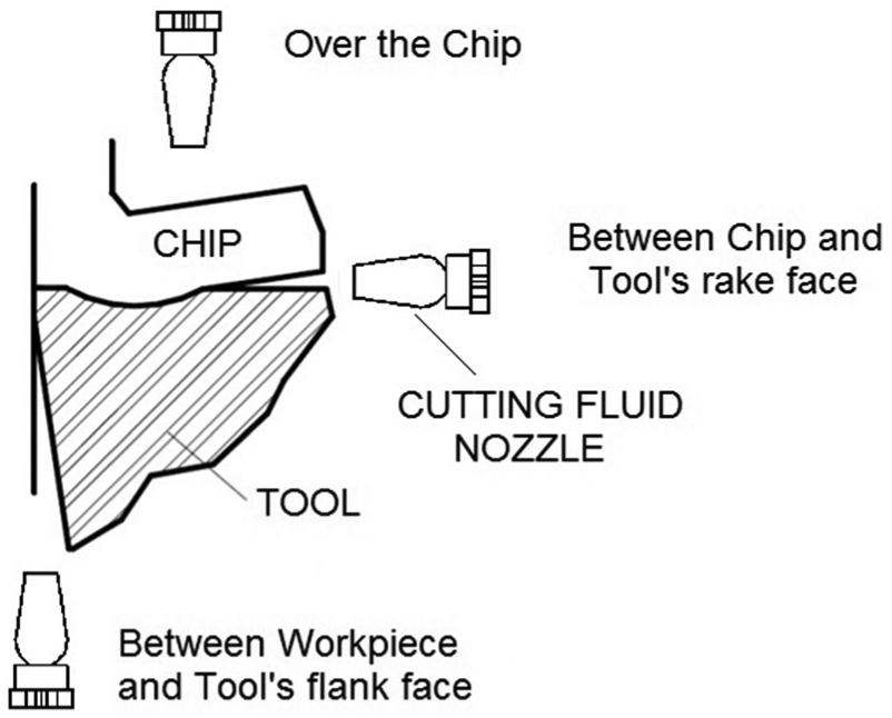
Possible directions of the injection of cutting fluid in machining. 12
Trent and Wright 13 affirmed that high normal stress on the tool rake face during cutting makes the chip adhere to this face, forming a seizure zone at the chip–tool interface. In this zone, the chip velocity is zero and, consequently, a lot of shearing occurs inside the chip just above the rake face (this region with shearing is called flow zone). The shearing of the chip generates a lot of heat in this region. Due to the intense contact between chip and tool in the seizure zone (actual area of contact is equal to the apparent area of contact), the penetration of the fluid between chip and tool rake face in order to provide lubrication is almost impossible. Machado and Wallbank 14 affirmed that the high-pressure fluid does not lubricate the cutting zone at the tool’s tip, but it can provide some decrease in the seizure zone dimension and, consequently, to decrease the amount of heat generated by shearing in the flow zone and the temperature of the tool in this region. In the vicinity of the seizure zone is the sliding zone, where the contact between chip and tool is not so intense, making the penetration of the fluid possible. In this case, the fluid correctly directed toward this region and under high pressure may have some lubrication effects, and also to efficiently decrease tool temperature, since it is reaching a zone very close to one of the heat generation zones (i.e. the flow zone). Kaminski and Alvelid 15 state that the high-pressure fluid on the rake face forms a wedge between the chip and the tool which decreases the size of the contact between them. Machado and Wallbank 14 also affirmed that the size of the sliding zone could be reduced if high-pressure coolant is used. The injection of the fluid toward the workpiece–tool flank face interface is also important, since flank wear is usually the type of wear which leads the tool to the end of its life. Therefore, the removal of heat from this face would harm the growth of some temperature-stimulated wear mechanisms. Crafoord et al. 16 affirmed that the high-pressure fluid injected toward the chip–tool interface reduces the heat generated by friction and makes the chip breakage easier. However, if the fluid is directed toward the tool flank face in turning operations, it has to overcome the volume of air moved by the workpiece rotation, which is very difficult if it is injected under low pressure, mainly when high cutting speeds are used. 17 High-pressure coolant directed toward tool flank face has much better possibilities of getting close to the contact between workpiece and tool and, consequently, to provide an efficient cooling of it. It seems that the injection of the fluid toward the upper face of the chip is not suitable, since the fluid does not get close to the heat generation zones (interfaces between chip and tool and between tool and workpiece). However, most of the regular cooling systems of the machine tools (mainly lathes) using low pressure throw the fluid all over the areas around the cutting zone, making it to abundantly reach the upper face of the chip.
De Angelo Sanchez et al. 18 performed turning experiments in a difficult-to-machine steel using several ways of injecting fluid, including high-pressure fluid (30 bar). They observed that the use of high-pressure fluid increased tool life and decreased cutting forces when the fluid was directed toward the chip–tool interface.
Klocke et al. 19 investigated the effect of high-pressure coolant applied toward the tool–chip interface in the turning process of Inconel 718 and Ti6Al4V with cemented carbide tools. The influences of the cutting fluid pressure (up to 300 bar) and flow rate (55 L/min) on tool temperature, tool wear, chip forms and the ratio of cutting forces/tool–chip contact area were analyzed. Experiments with conventional flood coolant supply were also performed. They verified a 25% decrease in the tool temperature when high-pressure fluid was used. Moreover, due to a change in the mechanical load on cutting edge and the variation of the tool wear mechanisms caused by the high-pressure fluid, tool life was increased up to 50% when high-pressure fluid was used.
As opposed to what was affirmed in the last paragraph, the results of the experiments performed by Ezugwu et al. 20 showed that the use of high-pressure coolant in the machining of Inconel 901 nickel-based alloy shortened tool life when compared to the machining with flood coolant. They explained this result affirming that the use of high-pressure coolant shrank the tool–chip contact area, which increased the compressive stress at the cutting edge and had low effect on cutting forces. Therefore, the pressure on the tool increased, notch wear was stimulated and tool life was shortened.
The results obtained by Sharman et al. 21 also did not follow the usual trends of results. These authors developed a series of Inconel 718 turning experiments verifying the influence of cutting fluid pressure and direction on tool life and chip breakability. Tool life was not affected by the use of high-pressure fluid up to 450 bar of pressure. The high pressure coolant injected toward the tool flank face was able to reduce flank wear rate, but since the notch wear rate was not affected, tool life was not affected too, once this kind of wear determined the end of tool life. When fluid was applied at 150 bar of pressure, it was able to decrease the chip size. Moreover, the use of high-pressure fluid also did not influence the level of surface integrity, but when 450 bar of pressure directed toward the flank face was used, the level of tensile residual stresses close to the surface was reduced.
Since there are some disagreements about the use of high-pressure coolant in machining process of nickel-based alloys, this work has the purpose of testing this cooling strategy in the turning process of Inconel 625 alloy and also to check which fluid flow direction is more effective for the improvement of tool life and workpiece surface roughness.
Materials and methods
The tool life turning experiments on the nickel-based Inconel 625 alloy were performed in a computer numerical-controlled (CNC) lathe with 15 kW of power in the main motor and maximum spindle rotation of 4500 r/min with continuous variation of the spindle speed.
To follow the tool flank wear along the experiments, a stereoscope microscope was used with 40× of magnification, connected to a digital camera and to a computer containing image-processing software. With this equipment, tool flank wear could be measured and photographed several times along the tool life experiments.
After the tool life experiments, the worn tools were taken to a scanning electronic microscope with an energy dispersive X-ray spectrometer (EDS) device, which allows a semi-quantitative identification of the chemical elements present in some points of the tool wear land, in order to help in the tool wear analysis and to elaborate hypothesis of the tool wear mechanisms present.
Workpiece surface roughness was also measured several times along each experiment using a portable roughness meter. These measurements were carried out without removing the workpiece from the machine tool.
The workpiece used in the experiments was made of Inconel 625 alloy and had diameter of 152 mm and useful length of 40 mm, as can be seen in Figure 2. The turning operation was carried out in successive longitudinal passes (feed movement was in the axial direction), in such a way to make the workpiece diameter to decrease as the experiment was being carried out. Chamfers were built in the workpiece in the entrance and exit of the tool from the workpiece, in order to avoid sudden change of cutting force.
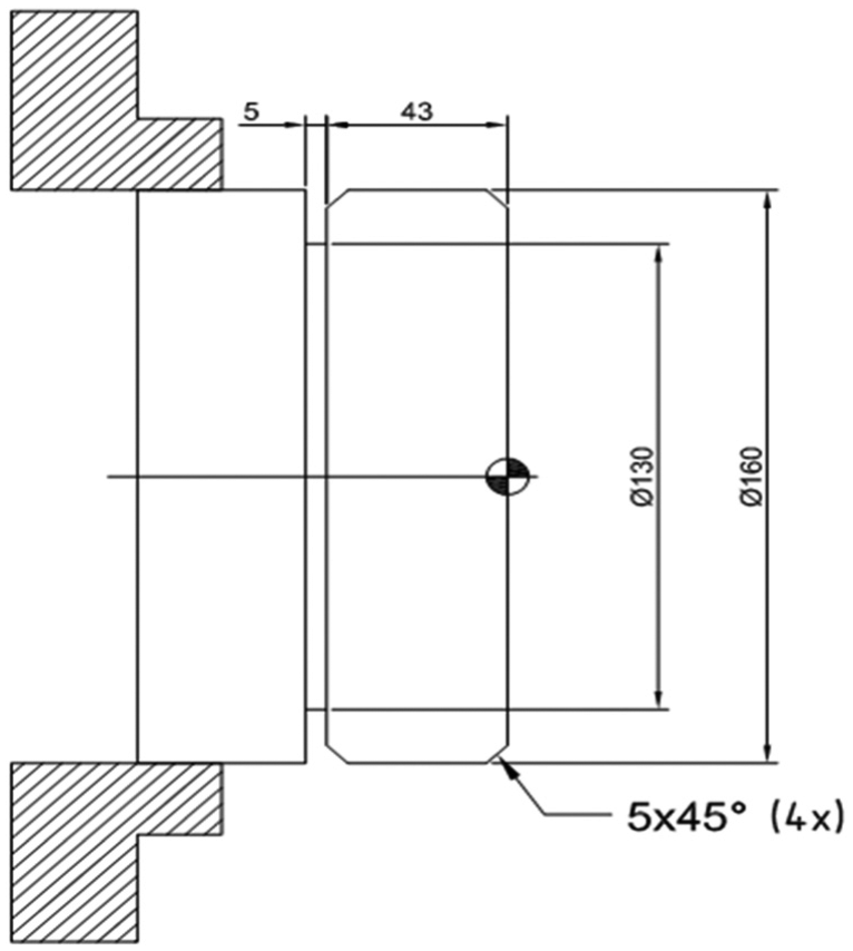
Scheme of the Inconel 625 workpiece fixed in the lathe chuck.
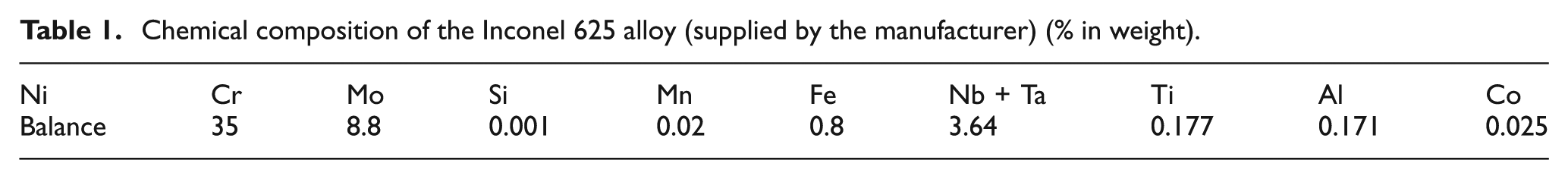
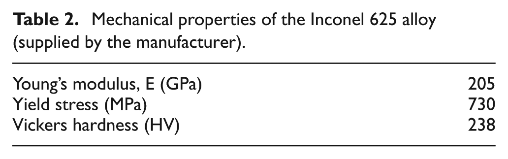
The Inconel 625 alloy used as workpiece in the experiments belongs to the δ, γ group of alloys. It is characterized by a fine grain structure during fusion (due to the δ phase) and excellent hardening ability by phase precipitation (due to the γ phase and the carbides dissolved in the matrix). The alloy chemical composition (supplied by the alloy manufacturer) is shown in Table 1. Its main mechanical properties are shown in Table 2.
Chemical composition of the Inconel 625 alloy (supplied by the manufacturer) (% in weight).
Mechanical properties of the Inconel 625 alloy (supplied by the manufacturer).
The turning tools used in the experiments were coated carbide inserts ISO code CNMG 12 04 04 GC1115 with the tool holder ISO code PCLNR 2525 M12. The tool holder places the tool with a negative geometry which confers to the tool a rake angle of −6°. It is necessary to add to this angle the geometry of the chip breaker, which confers to the tool a 17°–18° rake angle. In the end, the effective rake angle is between 11° and 12°. This tool material is fine grain cemented carbide, PVD-coated grade of the ISO code S20 (S15–S25). The substrate formed by WC+Co has high hardness (HV 1900), is heat resistant and has good resistance to plastic deformation. It is recommended for light to medium turning of heat-resistant superalloys like Inconel. It has a thin PVD coating (2.0–3.0 µm of thickness) based on TiAlN/AlCrO. 11
Two cooling conditions were used in the turning experiments: the first used the regular cooling system of the machine tool, with high fluid flow rate (8 L/min) and low pressure (this condition will be called flood coolant from now on) and the second used an auxiliary pumping system with high pressure of the fluid (70 bar) and high flow rate (80 L/min). Three different directions of the cutting fluid were used with high-pressure coolant: in the first, the fluid was directed toward the tool flank face (Figure 3(b))—in this condition, the distance between the hose and the tool nose was 8 mm; in the second, the fluid was directed toward the tool rake face (Figure 3(a)); and in the third, the flow rate was divided in two in such a way that the fluid was directed toward both rake and flank faces of the tool. In the experiments using flood coolant, the fluid was directed on the chip using the regular hoses of the machine tool.
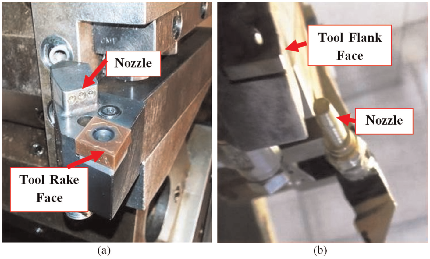
Directions of the fluid using high pressure: (a) toward the tool rake face and (b) toward the tool flank face.
Experimental photographs of the flow shape of the coolant could not be added since the jet is turbulent and emits a coolant mist that makes impossible the capture of images. The cutting fluid used in all experiments was an aqueous fluid with vegetable-based oil with 10% of oil concentration.
The cutting conditions used in the experiments were as follows: cutting speed vc = 65 m/min, feed f = 0.08 mm/revolution, and depth of cut ap = 1 mm. These cutting conditions were chosen based on the information of the tool supplier. 11
Each experiment was interrupted every 3 min of cut, when the tool was removed from the tool holder and taken to the stereoscope microscope to have its flank wear measured. Cutting tests and wear measurements continued up to the point the tool flank wear reached, VB = 0.3 mm, which was considered the end of tool life and, consequently, the end of one experiment. Each time the experiment was interrupted to wear measurement, workpiece surface roughness was also measured, three times in each machined surface (120° of interval between them). Each experiment was performed at least twice.
Results and discussion
Tool wear and tool life
Figure 4 shows the flank wear curves against cutting time for all the experiments.
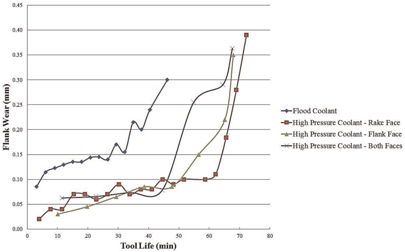
Flank wear against cutting time for all the experiments.
It can be seen in the figure that flank wear grew continuously with cutting time up to a certain point where the slope of the curve suddenly increased (increase in the wear rate), regardless the kind of cooling system used. Very likely, this increase in the wear rate occurred due to the removal of the tool coating layers, which made the tool substrate (much softer and with less wear resistance than the coatings) to have contact with the workpiece. It can also be seen in the figure that the moment of this change of wear rate is much later when high-pressure coolant was used, regardless the direction of the fluid flow, which made tool life in these conditions (high-pressure coolant) to be longer than when flood coolant was used.
Figure 5 shows the tool flank wear lands in the end of tool lives. It can be seen in the pictures of the figure that tool wear has an almost constant height along all the cutting edges when high-pressure coolant was used (Figure 5(b)–(d)). However, when flood coolant was used (Figure 5(a)), it can be seen that notch wear was present; that is, the wear height was higher in the end of the depth of cut. This kind of wear was the cause for the higher tool wear rate (and consequent shorter tool life) when flood coolant was used. Therefore, it is necessary to find an explanation why the high-pressure coolant was able to avoid the formation of notch wear. Due to the high ductility of the Inconel 625, a burr in the end of the depth of cut was formed during the cuttings, caused by the chip deformation. This burr occurred regardless the kind of coolant system used, as can be seen in Figure 6. This figure shows just the burrs formed in the beginning of the tool life when flood coolant and high-pressure coolant directed toward tool rake face were used in order to save space. But the same type of burr was seen in the cuttings using all cooling systems and not just in the beginning of tool lives but all along the lives.
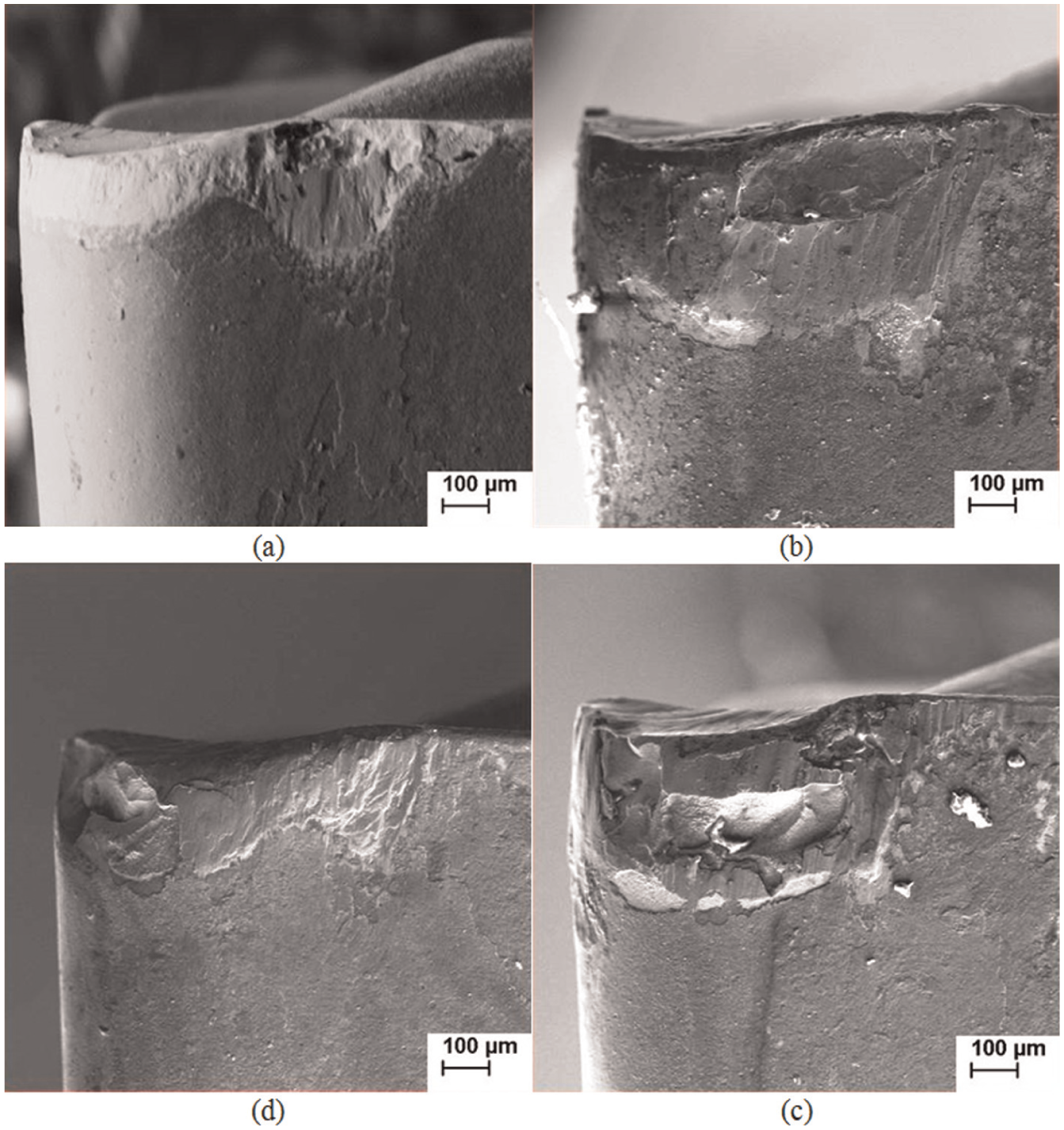
Images of the flank wear lands of the tools used in the experiments: (a) flood coolant, (b) high-pressure coolant toward tool rake face, (c) high-pressure coolant toward tool flank face and (d) high-pressure coolant toward both tool rake and tool flank faces.
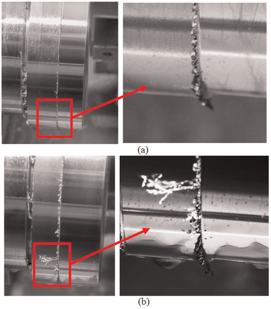
Burrs formed in the beginning of tool lives for (a) flood coolant and (b) high-pressure coolant directed toward the tool rake face.
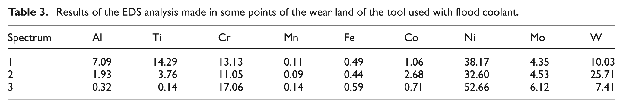
Due to the high hardening ratio of the workpiece material, these burrs had high hardness. Therefore, it had a furrowing effect on the tool coating. This furrowing effect promoted the premature removal of the tool coating in the burr region, the formation of notch wear (Figure 5(a)) and the consequent shortening of tool life when the flood coolant was used. When high-pressure coolant was used, due to its higher cooling capacity, the tool temperature did not increase so much and, consequently, the hardness of the tool coating was not strongly decreased, which made it strong enough to resist to the burr furrowing effect. Therefore, notch wear did not occur (Figure 5(b)–(d)), and the tool life increased when high-pressure coolant was used. The moment the burr torn the tool coating and made possible, the notch wear formation occurred for the experiment with flood coolant very likely around 25 min of cutting time, which was the moment flank wear curve changed its slope suddenly (Figure 4). When high-pressure coolant system was used, the removal of the tool coating along all the cutting edges (and not just in the end of the depth of cut) occurred when cutting time was higher than 40 min (Figure 4). Aiming a better comprehension of the tool wear mechanisms, Tables 3–6 show the results of the EDS analyses of some points of the flank wear lands of the tools used.
Results of the EDS analysis made in some points of the wear land of the tool used with flood coolant.
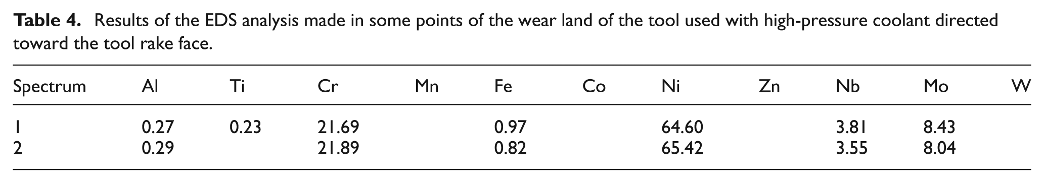
Results of the EDS analysis made in some points of the wear land of the tool used with high-pressure coolant directed toward the tool rake face.
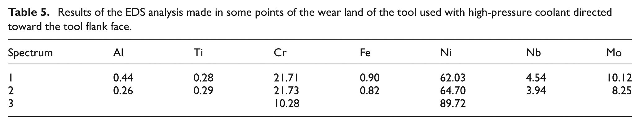
Results of the EDS analysis made in some points of the wear land of the tool used with high-pressure coolant directed toward the tool flank face.
Results of the EDS analysis made in some points of the wear land of the tool used with high-pressure coolant directed toward both the tool flank and tool rake faces.
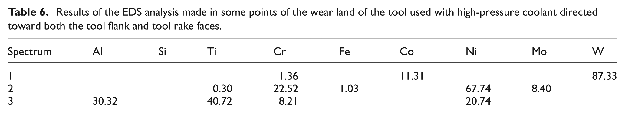
Table 3 shows the EDS results of some points of the tool used with flood coolant. The points of the table are shown in Figure 7.
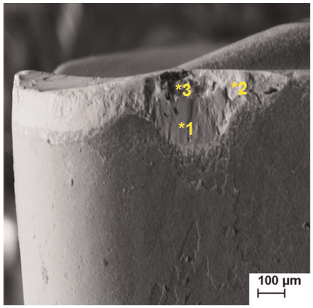
Flank face of tool used in flood coolant condition.
It can be seen in Table 3 a high level of workpiece material components like Ni and Cr. This fact indicates the adhesion of workpiece/chip material on the flank wear and especially in the region of notch wear. Therefore, the high cutting pressure made the material in the cutting zone to be extruded between tool and workpiece and adhere on the flank face. It can also be seen the presence of W on the wear land, indicating that under the workpiece/chip material adhesion layer, there was tool substrate material, that is, almost all tool coating had been removed. Just point 1 shows some presence of coating material (Ti), indicating the presence of some coating under the adhered material. Therefore, the wear mechanism in that region was attrition, which is the cyclical adhesion and removal of the adhered material together with tool particles. Notch wear was bigger than the regular flank wear because the furrowing effect of the burr already cited opened a furrow in the tool coating layer in that region, which stimulated attrition wear on the exposed tool substrate.
Table 4 shows the EDS results of some points of the tool used with high-pressure coolant directed toward the tool rake face. The points of the table are shown in Figure 8.
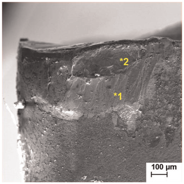
Flank face of tool used in high-pressure coolant toward rake face condition.
It was already cited, based on the analysis of Figure 1(b), that no notch wear occurred in this experiment. The EDS values of Table 4 show a massive adhesion of workpiece/chip material on the flank wear region (points 1 and 2), indicating that again the material in the cutting zone was extruded between workpiece and tool and adhered on the flank wear. Moreover, they indicate that the main mechanism of wear in this tool was again attrition.
Table 5 shows the EDS results of some points of the tool used with high-pressure coolant directed toward the tool flank face. The points of the table are shown in Figure 9.
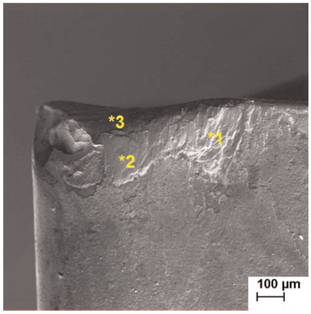
Flank face of tool used in high-pressure coolant toward flank face condition.
Again, it can be seen in the same table a massive presence of workpiece/chip material on the flank wear land of the tool, indicating that the wear mechanism did not change compared with that which occurred when the fluid was injected with high pressure and directed toward the rake face of the tool; that is, attrition was still the main tool wear mechanism.
Table 6 shows the EDS results of some points of the tool used with high-pressure coolant directed toward both the tool flank and tool rake faces. The points of the table are shown in Figure 10.
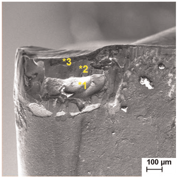
Flank face of tool used in high-pressure coolant toward both rake face and flank face condition.
The aspect of the flank wear land of this tool is a little different from those of the two other tools used with high-pressure coolant. Here, in point 1, just tool substrate material is present (W and Co), point 2 is predominantly formed by workpiece/chip material and in point 3, besides some workpiece/chip material (Ni and Cr), some tool coating materials are present (Ti and Al). Again, it can be concluded that attrition was the main wear mechanism. However, as this mechanism is characterized by cyclical adhesion and removal of material, it is possible that at the moment the picture was taken, the adhered material had just been removed, and the tool substrate was exposed. Besides that, the analysis shows that the tool coating still resisted in the region of point 3, even with a lot of workpiece/chip materials surrounding it.
Concluding the tool wear analysis, it could be seen that when the cutting was performed with flood coolant, the furrowing of the tool coating layer caused by the hard burr made the premature rupture of the coating in that region, which propitiated a massive adhesion of the workpiece/chip material, stimulating the attrition mechanism and causing notch wear. When high-pressure coolant was used, the lower temperature of the coating layer (due to the high efficiency of the cooling system) did not allow the coating to lose much hardness and, consequently, made the coating able to withstand the furrowing caused by the burr. Therefore, attrition spread all along the length of the contact between cutting edge and workpiece and produced a regular flank wear (roughly with the same height along the contact length). The different directions of the high-pressure cutting fluid did not change the wear mechanism.
Figure 11 shows tool lives for all the experiments of this work. The lines on the top of the bars in the figure depict the dispersions of the tool lives obtained in the replicas of the experiments.
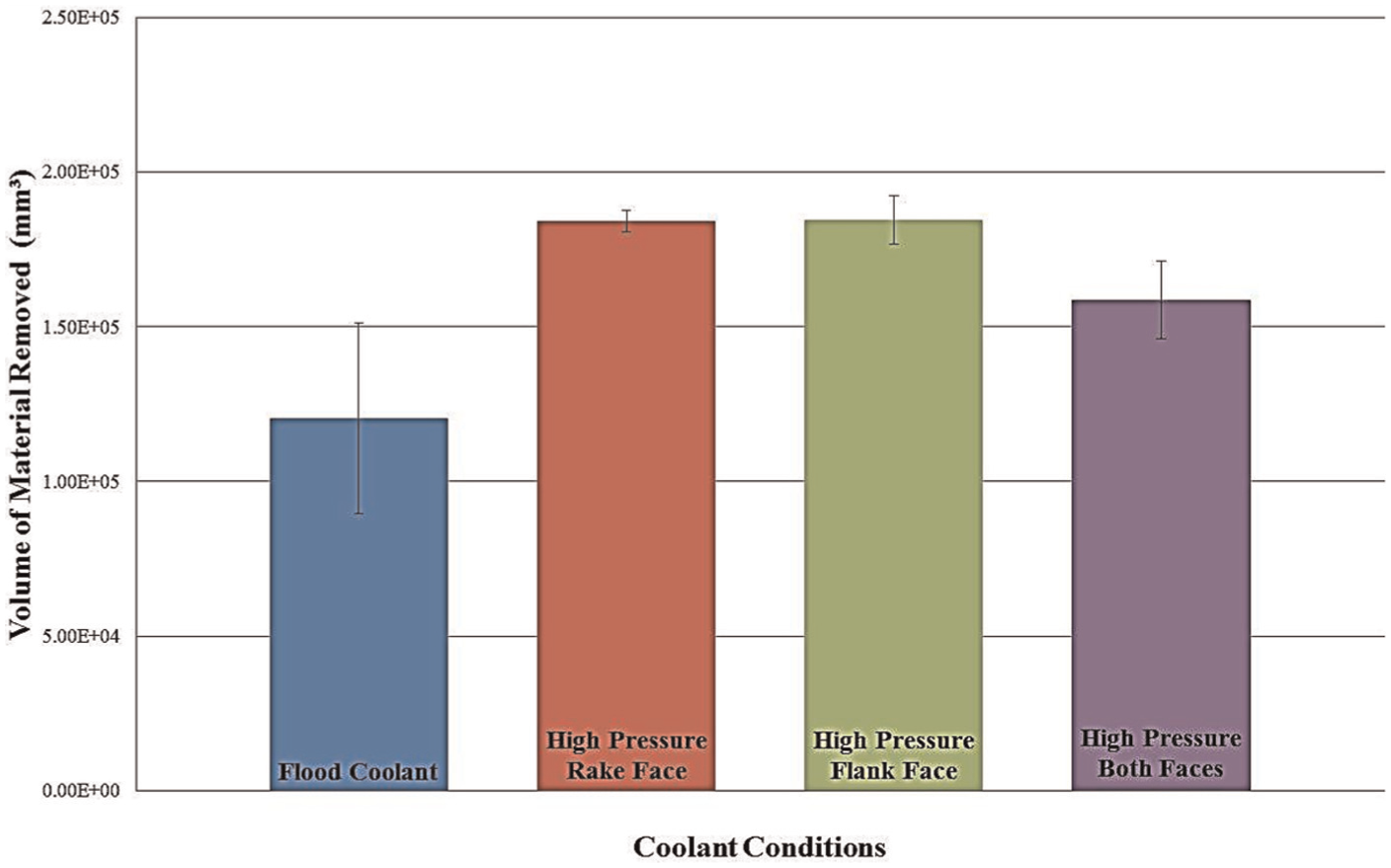
Tool lives and their dispersions for all experiments of this work.
It is possible to see in this figure that the higher cooling capacity of the high-pressure coolant systems, which avoided the formation of notch wear, promoted a considerable increase in tool life. In other words, when the wear occurs along the whole contact between workpiece and tool under attrition action, it is slower than when the furrowing effect of the burr in the end of the depth of cut region followed by attrition (which forms the notch wear) occurs.
Figure 11 also shows that the cutting fluid flow must not be divided into rake and flank faces. When this division was done, tool life was shorter than when the whole flow of cutting fluid was applied either toward rake face or toward flank face. Very likely, the smaller amount of fluid on each face of the tool decreased the cooling capacity of the fluid, increased the tool temperature and, consequently, decreased tool life when compared with the application of the fluid on just one face of the tool. The last thing that can be observed in Figure 11 is that there was no difference of tool life comparing the conditions of high-pressure fluid applied in the rake face and in the flank face.
Workpiece surface roughness
Surface finish is important for the behavior of the components during service, since the great majority of the component failures start at its surface. Figure 12 shows the surface roughness values (average roughness—Ra) obtained in the turning experiments at both beginning and end of tool life.
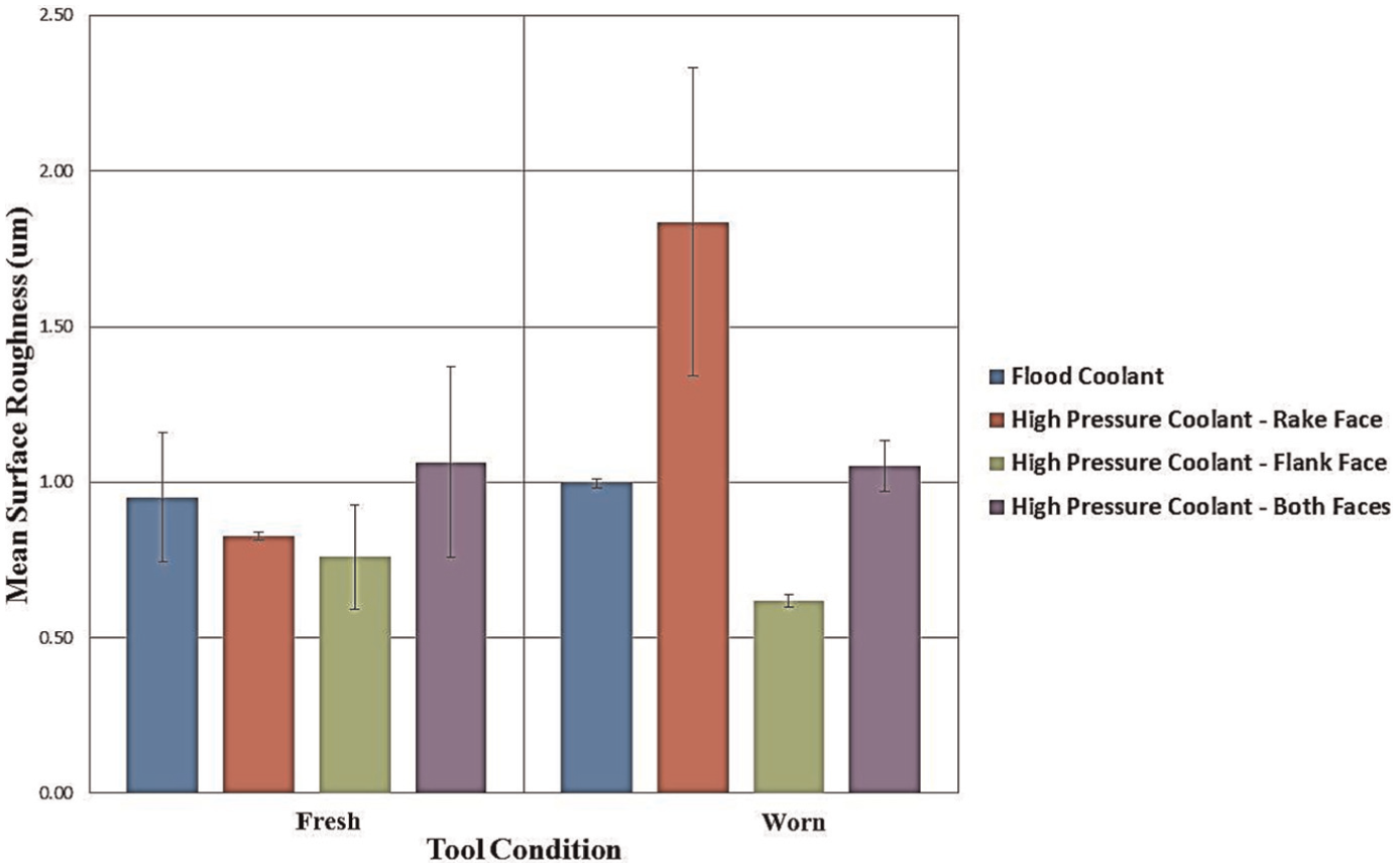
Average workpiece surface roughness, Ra, for the different cooling conditions used in the experiment in the beginning and in the end of tool lives.
Due to the scatter of the values, it cannot be affirmed which cooling condition is the best in terms of surface roughness in the beginning of tool life. However, if just the average values are taken into consideration, the use of high-pressure coolant directed toward either just the rake face or just the flank face is indicated to the turning of this nickel alloy. Since feed rate and tool nose radius were the same for all the experiments (they contribute to the geometric formation of the roughness) and there is no reason to think that tool/workpiece vibration was different among the experiments, it seems that the good cooling capacity of the fluid in these two conditions was also important to minimize the workpiece surface strain and, consequently, to decrease surface roughness.
The surface finish of the workpiece produced in the end of tool life is strongly influenced by the tool nose shape, which varies along the cutting depending on the tool wear. The results of Figure 12 show that great alterations of the surface roughness from the beginning to the end of tool life did not occur for flood coolant and for high-pressure coolant directed toward both rake and flank faces, which indicates that the tool wear did not cause large changing of tool nose shape. But, what is worthy to be cited is that when high-pressure coolant directed toward the tool rake face was used, the surface roughness was twice higher in the end of tool life. Very likely, this was caused by the formation of little cracks on the tool nose caused by the injection of the fluid in that region, which changed the nose shape and, consequently, made surface roughness to increase. When high-pressure fluid was applied just toward the flank face, the roughness value in the end of tool life was a little smaller than in the beginning of tool life, very likely due to the sharpening of the secondary cutting edge caused by the cutting. This was the condition which presented the smallest value of surface roughness in the end of tool life.
To finish this work, taking into consideration the tool wear and tool life values and also the workpiece surface roughness, it can be stated that the best cooling condition for turning Inconel 625 alloy is the application of the fluid with high pressure and directed toward the tool flank face. This condition generated one of the longest tool life (but similar to those obtained with high-pressure coolant directed toward the tool rake face) and the smallest values of workpiece surface roughness in the beginning (however, close to the values obtained in other conditions) and in the end of tool life (much smaller than the values in the other cooling conditions).
Conclusion
It can be concluded, for the turning of Inconel 625 nickel-based alloy in conditions similar to those used here, as follows:
The use of high-pressure coolant promoted tool life increase.
The direction of the flow of cutting fluid in high-pressure coolant (whether toward tool rake face or flank face) did not influence tool life, provided there was no division of the flow rate. When high-pressure coolant was injected in both tool faces (rake and flank) with half of the flow rate on each face, tool life was shorter than when the high-pressure fluid was injected with all the flow rates directed toward just one of the faces.
In terms of workpiece surface roughness, the injection of the high-pressure fluid directed toward the tool flank face generated lower surface roughness in both the beginning and end of tool life.
When flood coolant was used, notch wear was the main type of wear, and it was caused by the furrowing effect of the hard burr on the tool coating in the end of the depth of cut, followed by the attrition wear mechanism.
When high-pressure coolant was used, the higher cooling efficiency of the fluid injection avoided much of the hardness loss of the tool coating caused by the temperature and, consequently, made it more resistant to the furrowing effect of the hard burr. Consequently, notch wear did not occur. In these conditions, flank wear was the main type of wear, and attrition was the main wear mechanism.
Footnotes
Acknowledgements
The authors would like to thank Sandvik Coromant for supporting this research.
Declaration of conflicting interests
The author(s) declared no potential conflicts of interest with respect to the research, authorship and/or publication of this article.
Funding
The author(s) received no financial support for the research, authorship and/or publication of this article.