
Abstract
Abundant application of cutting fluids may increase production cost and cause environmental and health damages, particularly when not properly managed. Thus, alternative measures are needed to overcome the difficulties of using cutting fluids. If sustainable and ecological manufacturing aspects are envisaged, any attempt to improve the machinability of such difficult-to-machine material is always welcome. In this direction, this research work aims to develop experimental set-up as a possible approach to fostering sustainability in metal cutting lubrication to supply solid lubricant at minimum quantity and also to study the effect of applying solid lubricant (molybdenum disulphide and graphite) mixed with oil, during turning of Inconel 718 using cemented carbide tools. The concentration of the solid lubricant in the fluid and the flow rate of the mixture were varied to analyse the main output parameters such as surface roughness, cutting forces and tool life. Experimental findings of this study show that minimum quantity solid lubricant consisting of molybdenum disulphide and oil mixture performed better, and therefore, it may be considered to be a cost-effective and environmental-friendly lubrication technique than flood coolant and sprayed oil with or without graphite to retard all types of damaging processes and to improve machinability characteristics of Inconel 718.
Introduction
The nickel-based superalloy (Inconel 718) presents excellent mechanical properties which combined with high corrosion resistance at elevated temperatures and good strength per weight ratio makes this material to be largely applied in components of gas turbines, aerospace engines, nuclear reactors, pumps and so on. 1 However, machinability of nickel-based alloy is extremely complex due to its high work hardening ratio, low thermal conductivity and high chemical affinity with most materials used as cutting tools that accelerate tool wear, poor surface quality and diminish productivity. 2 Nickel alloys tend to adhere onto the tool surface due to the high temperature presented at the cutting edge during machining (>1000 °C), and at low cutting speed conditions, the built-up edge is frequently observed.3,4 The high cutting forces acting in the shearing zones promote high friction with high heat generation and consequently develop high temperature that accelerates tool wear. 5 Application of a cutting fluid in machining processes has two main objectives: (1) diminish friction by lubricating action and (2) reduce cutting temperature by a cooling action. As lubricant delivered in the machining zone, the cutting fluid must be present at the chip–tool–workpiece interfaces and be active (preferably combining with the materials) to form layers with reduced shearing strength and friction. The application of cutting fluid increases the thermal convection. The combination of these lubri-cooling actions reduces tool wear, improves surface quality and augments productivity.
However, government of most countries is pressuring companies to reduce or if possible abolish the indiscriminate use of environmental effect cutting fluids, due to possible environmental and health damages that they might offer. 6 Ecological processes impose new demands and one possible solution is the use of minimum quantity lubricant (MQL). The technique uses compressed air that carries oil droplets in a mixture that is pumped and directed to the cutting regions to exert its role adequately. The lubricating action is ensured by the oil droplets while the cooling action, although not the most efficient, is given by the compressed air. The oil droplets are either of vegetable oil or mineral-based oils, and the flow rates are very small (usually ranging from 10 to 200 mL/h). MQL has been widely used in many machining processes such as turning, milling, drilling and grinding.7,8 The small amount of oil is enough to reduce the tendency of work material to adhere onto the tool surfaces and diminish friction. 9 In turning of Inconel 718, the technique has been applied by several researchers showing good results in terms of reduction in tool wear and improvement in surface integrity.4,10,11
The use of solid lubricant in powder form 12 can be applied in the machining process or solid lubricants mixed with oils. They can be applied by different methods such as graphite, by mixing them in compressed air and directing the flow to the cutting region13,14 or by an electrostatic field that attracts the solid lubricant powder onto the cutting region. 6 Good results were found in terms of reduction in cutting forces and improved surface roughness and tool lives when using these techniques. Using an automatic feeder, solid lubricants in a powder form have been applied directly to the machining zone. Although the sufficient coolant is applied in the machining zone, there is still a need for flushing action for cleaning of components which makes solid lubricants less attractive than conventional cooling techniques. Instead of using solid lubricant in powder form, semi-fluid lubricant containing a thickening agent of solid lubricant mixed with water-based soluble oil and grease has been used. 8 However, the application of powder form produced significantly low cutting forces, due to the ineffective removal of semi-solid lubricant, and formed chips is the major limitation of this method. Finally, the application of water-based oils has been performed under MQL conditions. Experiments have been conducted using water-based oils under MQL conditions. 13 The mixture of solid lubricants with mineral based oils (molybdenum disulphide and graphite) with an average particle size of 250 nm at various concentrations of solid lubricants (5% and 20 wt% with respect to oils) have been used. The obtained results are very encouraging in terms of reduction in cutting force and better improvement in tool life, but solid lubricants (nano-materials) significantly increase the overall cost.
In addition to the morphology and crystal structure of the solid lubricant particles, the size and quantity of the particles play a dominant role in the lubrication process. Further, the application process of solid lubricant at the tool-chip interface influences the lubrication characteristics during machining process. Mixed with oil, the solid lubricant can also be applied by the MQL technique. Some work has shown good results, for example, Rahmati et al. 15 applied the mixture of MoS2 nanoparticles (20 -60 nm) with oil at several concentrations (0.0, 0.2, 0.5 and 1.0%wt) with a flow rate of 20 mL/h, on Al6061 -T6 (work material) and conducted experiments on end milling process. The results indicate that nanoparticles of molybdenum disulphide at 0.5%wt, improved the surface quality of the workpiece when compared with other concentrations. The nanoparticles of molybdenum disulphide improved surface quality of the workpiece and the concentration of 0.5% wt presented the best result.
The above-mentioned studies indicate that the application of solid lubricant–assisted machining is a new technique to control the machining zone temperature without polluting the environment and the great potential of using solid lubricants for low-cost machining under different conditions.12,15 In addition, the present studies also indicate that the application of solid lubricant during machining of nickel alloy was not available in the literature. This has encouraged this work to carry with an aim on developing an application method, namely, minimum quantity solid lubricant (MQSL) which eliminates the use of bulk amount of solid lubricants and also to study the effect of using MQSL mixed with a vegetable-based cutting oil applied during turning of Inconel 718 with cemented carbide tools triple physical vapour deposition (PVD) coated with TiAIN/(Al,Cr)2O3/TiAIN. The concentration of the solid lubricants and the flow rate were varied, and the performance assessment has been made by considering surface roughness, the machining force components, micro structure, hardness and the tool life as performance indices.
Literature review
Machining of high-performance engineering and hard materials is usually associated with high machining costs and low productivity. Hard materials (typical examples are nickel alloys) are known as very difficult-to-machine materials which are widely used increasingly in a number of high-performance applications including automobiles, aerospace, textiles and other manufacturing industries. Close tolerances and a good surface finish will become critical for their application. Therefore, the machining of these high-performance alloy materials is becoming necessary to be able to meet service requirements. The main factors that cause machining difficulties are their low thermal conductivity and high levels of hardness. Although the extremely high hardness of nickel alloys is one of their most important service features, it results in the difficult penetration of cutting tools, hence cutting tools deteriorate rapidly. Furthermore, generated micro-cracks on surfaces and chipping in the comer of ground components, will adversely affect the surface integrity and the quality of components.
In manufacturing industry, machining performance has been assessed by various parameters such as surface finish, cutting forces and tool wear. It has long been recognised as they have considerable impact on product quality, productivity and overall economy. Such parameters largely depend on several factors; among them, nature of contact conditions, material and geometry of the cutting tool and mechanics of machining exist between tool–work material play a very significant role. In fact, the frictional interaction between the chip and the tool at the rake face has major influence in determining tool wear and characteristics of the machined surface. It is believed that any change in the contact conditions, as a means of better control over frictional interaction, results in a change in the chip–tool contact and mechanics of machining, thereby influencing the contact temperatures, tool wear, cutting forces and energy consumption. 12
During machining of hard-to-cut materials, coolants/lubricants act as an important role to ensure good product quality, due to high friction and high temperatures developed in the machining process. Conventionally, liquid coolants are employed in machining zone. But application of metalworking fluids causes skin problems and bio-degradable problems. Therefore, the significant improvement towards sustainability will be one of the most important challenges in near future.
Varadarajan et al. 16 have studied the performance of application of minimal fluid application when turning of difficult-to-cut materials and compared the results with conventional wet and dry machining. It was found that the obtained results of minimum cutting fluid are encouraging in terms of cutting force to that of conventional machining conditions. Rahman et al. 17 applied 42 L/min (flood coolant) as coolant; the results are compared with MQL of 8.5 mL/h and the comparative effectiveness was investigated in terms of surface finish, cutting force and chip shape. From the obtained results, it is revealed that better surface finish has been found in MQL condition when compared with dry and flood cooling application. The study of this research has found that MQL may be considered as a sustainable machining technique. Dilbagh and Rao 18 carried out experiment on turning operation and applied graphite and MoS2 solid lubricant as coolants. Surface finish and cutting force results are all influenced beneficially under MoS2-assisted machining and are compared with graphite-assisted machining and flood coolant. The inferior results of surface roughness obtained by MoS2 can be attributed to its strong adhesion tendency compared to graphite. Applying solid lubricants (graphite and molybdenum disulphide) as coolants in the machining operation is one alternative method to conventional wet and dry machining. Solid lubricant–assisted machining produces low value of cutting force and surface finish compared to dry turning process.
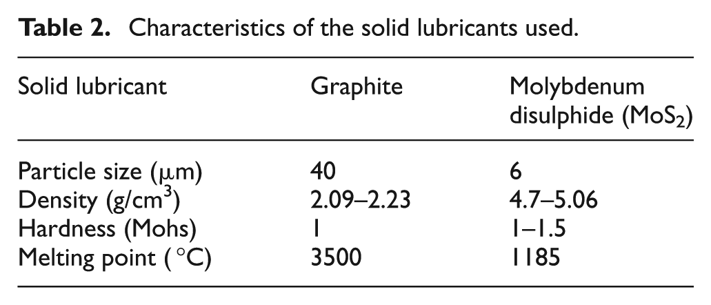
Increasing demands for more accurate and precision components with high integrity and the machining technology of hard materials needs to be significantly developed. Reddy et al. 6 have been working in the area of MQSL to achieve sustainable manufacturing using clean machining processes, such as graphite and molybdenum disulphide.6,19,20 The surface and surface characteristic results obtained by MQL are in terms of reduction in cutting zone temperature due to its favourable changes in chip–tool and work–tool interaction. In MQL process, the widely used solid lubricants are graphite and molybdenum disulphide due to their crystalline lattice structure. Due to their crystalline lattice in the form of dry powder are effective lubricant additives. The layers of the structures can be easily sheared in the direction of motion over each other resulting in reduction in friction. Larger particle size has high number of layers which can be more suitable for relative rough surfaces at moderate speeds, whereas smaller particle sizes are suitable for smoother surfaces for low-speed conditions. Other components that are useful as solid lubricants in addition to the earlier widely used graphite and MoS2 include boron nitride, polytetrafluorethylene (PTFE), talc, calcium fluoride, cerium fluoride and so on.
The previous research work clearly specifies that there is a need to concentrate efforts in the direction of solid lubricant–assisted machining to overcome the high heat generation in machining advanced engineering materials. Furthermore, if the lubricant can be applied in a refined and defined way, just sufficient for lubrication, improved process results (reduction in machining cost, improvement in tribological properties, improvement in surface integrity, thereby overall increased productivity) may be expected. Hence, an attempt has been made in this research work to develop an experimental set-up, namely, MQSL to supply solid lubricant continuously and effectively to the machining zone. This work also experimentally investigates the role of minimum quantity solid lubrication–assisted machining on surface and subsurface parameters during turning of hard-to-cut Inconel 718 material at selected speed–feed combinations by cemented carbide triple PVD-coated (TiAIN/(AlCr)2O3/TiAIN) tools and compares the effectiveness of MQSL with that of MQL and conventional cutting fluid. Finally, to comprehend the wear mechanisms of worn surfaces, microscopic examinations were conducted.
Experimental procedure
The first objective of this research work is to design an experimental set-up aiming to improve the machinability performance of Inconel 718 alloy and fabricate the related infrastructure. The developed experimental set-up as shown in Figure 1 comprises spray nozzle, air pressure controls, fluid pump and air compressor. The thin but high-velocity stream of MQSL was projected along the auxiliary cutting edge of the insert, as indicated in a frame within Figure 1, so that the coolant reaches as close to the chip–tool and the work–tool interfaces as possible. The MQSL jet has been used mainly to target the rake and flank surface along the auxiliary cutting edge and to protect the auxiliary flank to enable better dimensional accuracy. All the main components are connected by hoses, cables, all the necessary regulators and fittings. The purpose of air compressor is to fluidise the solid lubricant mixture by passing air through the powder mixture container and then to transport the same to the spray nozzle. The solid lubricant mixture flow is regulated by controlling the air supplied to the powder mixture container. The nozzle was designed and manufactured using electrical discharge machining (EDM) machine, in such a way that the lubricant flows continuously on to the tool–work interface. After ensuring the experimental set-up for proper lubrication (required constant flow rate), experiments were carried out to assess the machinability of nickel alloy.
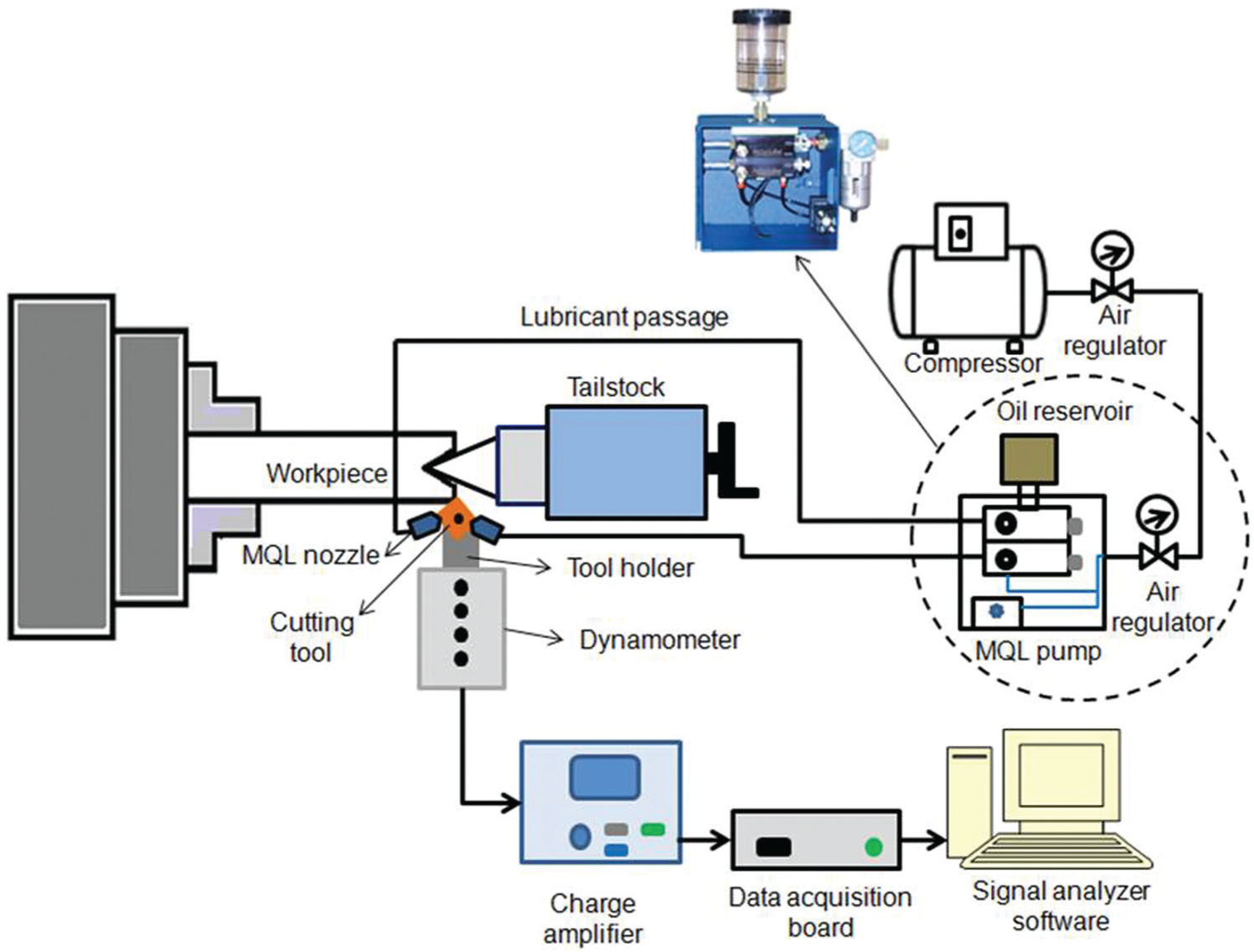
Schematic diagram of developed minimum quantity solid lubricant (MQSL) experimental set-up to improve machinability of nickel alloy.
The machining tests were carried out using a computer numerical control (CNC) lathe Multiplic 35 D, manufactured by Industrial Romi S.A., having 16 kW of power and spindle speed varying from 10 to 3000 r/min. The cylindrical bars of Inconel 718 in the annealed condition with an average hardness of 214 HV30 and workpieces were of diameter 101 mm and 250 mm length. The details of experimentation are shown in Table 1.
Experimental conditions.
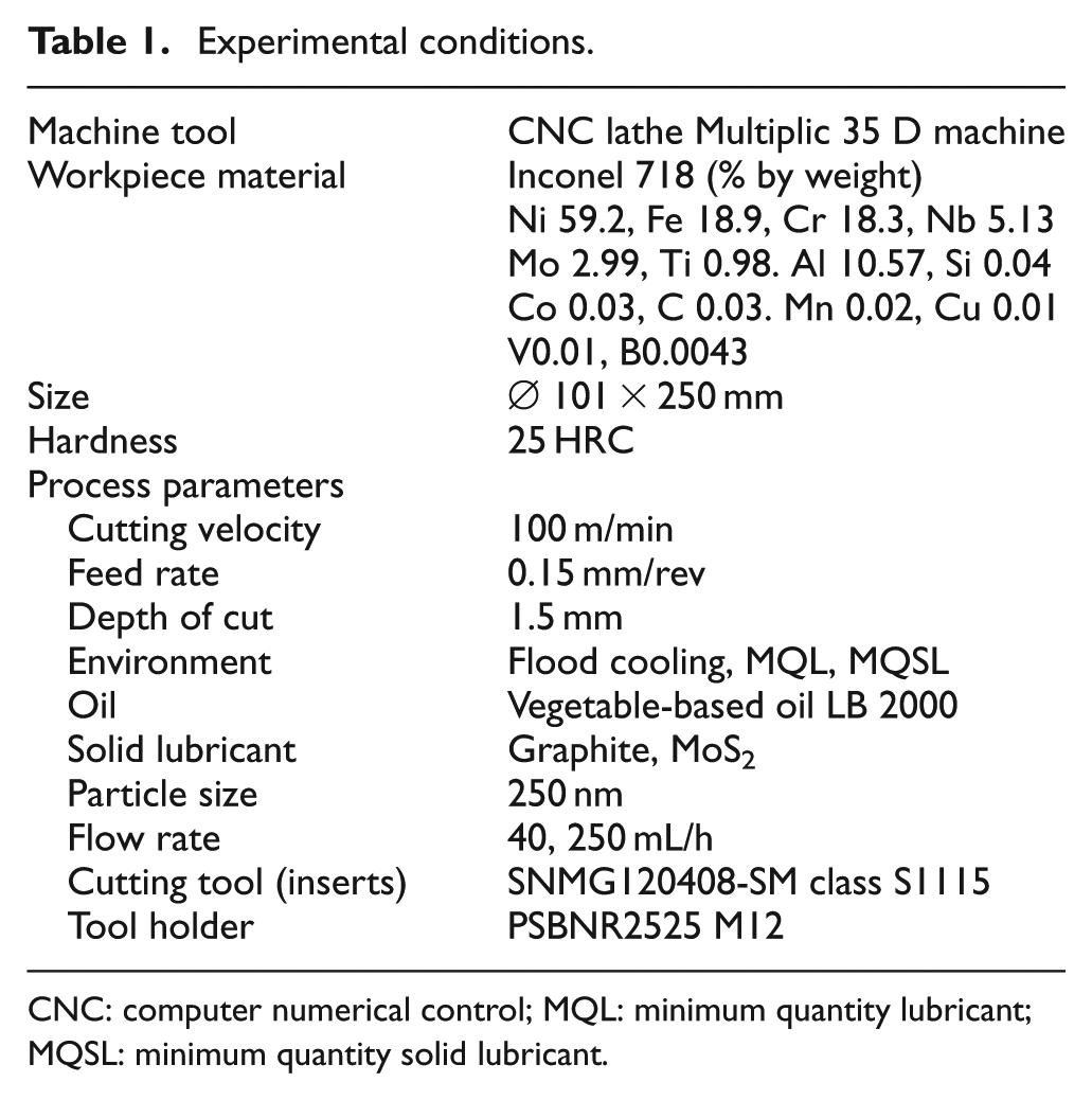
CNC: computer numerical control; MQL: minimum quantity lubricant; MQSL: minimum quantity solid lubricant.
The cutting tools used in the experimentation were cemented carbide inserts with ISO designation SNMG120408-SM class S1115. All the tools have integrated chip-breaker and are coated with TiAIN/(AlCr)2O3/TiAIN PVD coatings. The tool holder was an ISO PSBNR2525 M12 and cutting insert is mounted on it, which has side cutting edge angle of 15°, a rake angle of −6° and a relief angle of 6°.
During the experiments, the cutting speed, feed rate and depth of cut were kept constant at 100 m/min, 0.15 mm/rev and 1.5 mm, respectively. Two sets of tests were planned; the first is to investigate the behaviour of the surface roughness, micro hardness and machining force components and the second for the tool life determination. In the first set of tests, a new cutting edge was used in each condition. In the second set of tests, the same tools that are used in the first set were used to continue for the tool life tests.
Two different solid lubricants, graphite and molybdenum disulphide, were mixed with a cutting fluid and applied to the cutting region by the developed MQSL technique. The cutting fluid, vegetable-based oil LB 2000, was manufactured by ITW Chemical Products Ltd. The compressed air pressure was fixed at 0.5 MPa and the concentration of the each solid lubricant was 0% and 20%. Two flow rates of the mixture such as 40 and 250 mL/h were tested. As a base of comparison, flood cooling was also tested. In this case, vegetable-based soluble oil Vasco 1000 manufactured by Blaser Swisslube do Brasil Ltd in a concentration of 8% and flow rate of 4.5 L/min was used without mixing solid lubricant. Table 2 presents the characteristics of the solid lubricant used.
Characteristics of the solid lubricants used.
In the first set of tests, for each lubri-cooling condition, a machining pass was performed with 20 mm of feed length. During the cut, the three machining force components (cutting force, radial force and feed force) were monitored, and after the machining operation, the micro hardness and surface roughness were measured. In the second set, the experiments carried out in the first set for each condition were continued (after the tool wear was measured) until the maximum flank wear reached 0.6 mm, the same value used as end-of-tool life criteria.
The machining force components (cutting, feed and thrust forces) were measured using a piezoelectric dynamometer model 9265B and a charge amplifier model 5070A both manufactured by Kistler. The acquisition rate was 500 Hz for 5 s in each test. Three tests were performed with same machining condition and the average values of the obtained cutting forces were determined. The acquisition system was controlled by an analogue-to-digital (A/D) board model USB DAQPad-6251 and LabVIEW® 7 software both produced by National Instrument.
The surface roughness (Ra) was measured using a roughness meter model SJ-201P manufactured by Mitutoyo which has 0.01 µm of resolution and the cut-off of 0.8 mm was used, according to NBR ISO 4287:2002 21 standard. The flank wear of the tools was measured using an OLYMPUS stereomicroscopy, model SZ6145TR and Image Pro-Express software, after proper calibration. Micro hardness measurements on the samples were performed under the load of 200 g applied for 15 s using the SHIMADZU micro hardness tester. The average value of six tested samples was used to plot the micro hardness graph.
Results and discussions
Within the framework of an optimisation of the cutting process, the knowledge of the surface and subsurface characteristics is essential to understand the machinability of any material. Experiments were carried out at the selected cutting speed, feed rate and depth of cut under the following cutting conditions:
Wet machining;
MQL-assisted machining without mixing with any solid lubricant at flow rates of 40 and 250 mL/h;
MQSL-assisted machining with the following conditions:
(a) 20% concentration of graphite mixed with oil at flow rates of 40 and 250 mL/h;
(b) 20% molybdenum disulphide at 40 and 250 mL/h mixed with oil at flow rates of 40 and 250 mL/h.
All the above cutting conditions have been used to analyse the machinability characteristics of the hard-to-machine (Inconel 718) work material mainly with respect to surface finish, cutting forces, micro hardness and tool wear (flank wear and nose wear). The main cutting parameters (cutting speed, feed rate and depth of cut) were selected based on the preliminary testing conditions. The cutting conditions selected after testing preliminary to the definitive tests were as follows: cutting speed is 100 m/min, feed rate is 0.15 mm/rev and depth of cut is 1.5 mm. These parameters were chosen based on the -day industrial requirements and kept constant throughout the tests.
Surface roughness
Surface roughness (Center Line average [CLA]: Ra) is one of the most important surface roughness parameters to express the quality of a machining process and it depends on several factors and variables of the system (material property, tool geometry and cutting tool material, applied cutting fluid, cutting conditions and method of application, machine tool rigidity, among others). Under such high cutting temperature, the solid lubricant melts and smears creating a thin lubricating film on the rake face of the tool. The Ra parameter was measured in three different positions on the bar of 20 mm machined surface under different environmental cutting conditions considered in this research work. The average final results include a test and two replicas in each condition. Figure 2 shows the average results of Ra (surface roughness) obtained under different environmental cutting conditions.
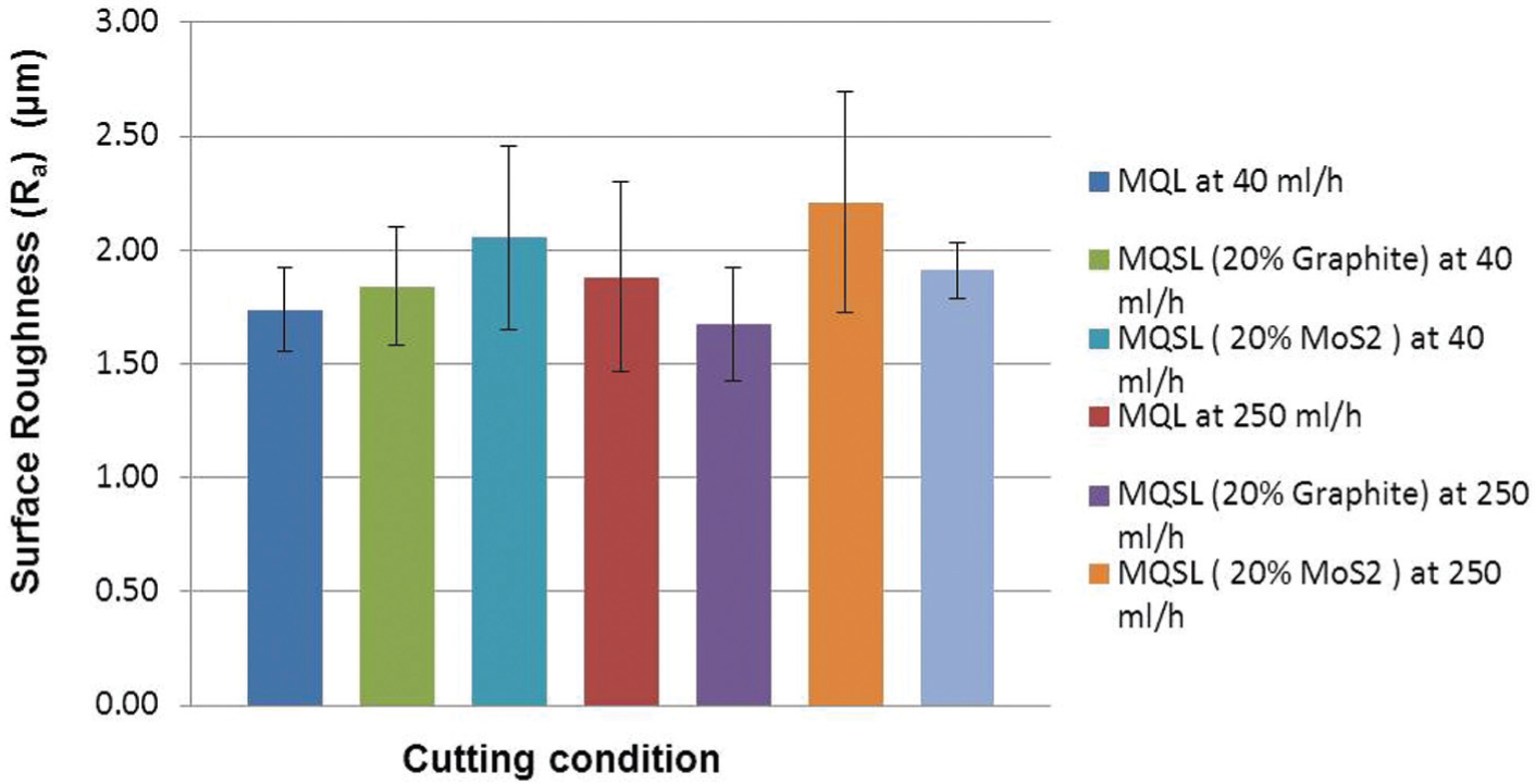
Surface roughness (Ra) at cutting speed = 100 m/min, feed = 0.15 mm/rev and depth of cut = 1.5 mm under different lubri-cooling conditions.
It has been observed from Figure 2 that the Ra was not affected significantly under the considered different environmental conditions after analysing the standard deviation bars. However, based on the average values, the flood cooling and MQL condition without solid lubricant at 40and 250 mL/h presented averages of Ra parameter (shown in Table 3) between 1.7 and 1.9 µm. The average values of Ra when using graphite were the highest among the lubri-cooling conditions tested (2.21 µm at the flow rate of 250 mL/h and 2.05 µm at the flow rate of 40 mL/h). The addition of MoS2 with MQL presented Ra average values closer to those shown by the MQL technique (machining without solid lubricant). With 40 ml/h flow rate of MoS2, Ra was 1.80 µm and with 250 ml/h flow rate of MoS2, Ra was 1.67 µm (smallest value produced). Except for the test using MoS2, the other conditions (MQSL with MoS2 and MQL) showed higher average Ra values with increase in flow rate from 40 ml/h to 250 ml/h.
Surface roughness (Ra) at different cutting conditions.
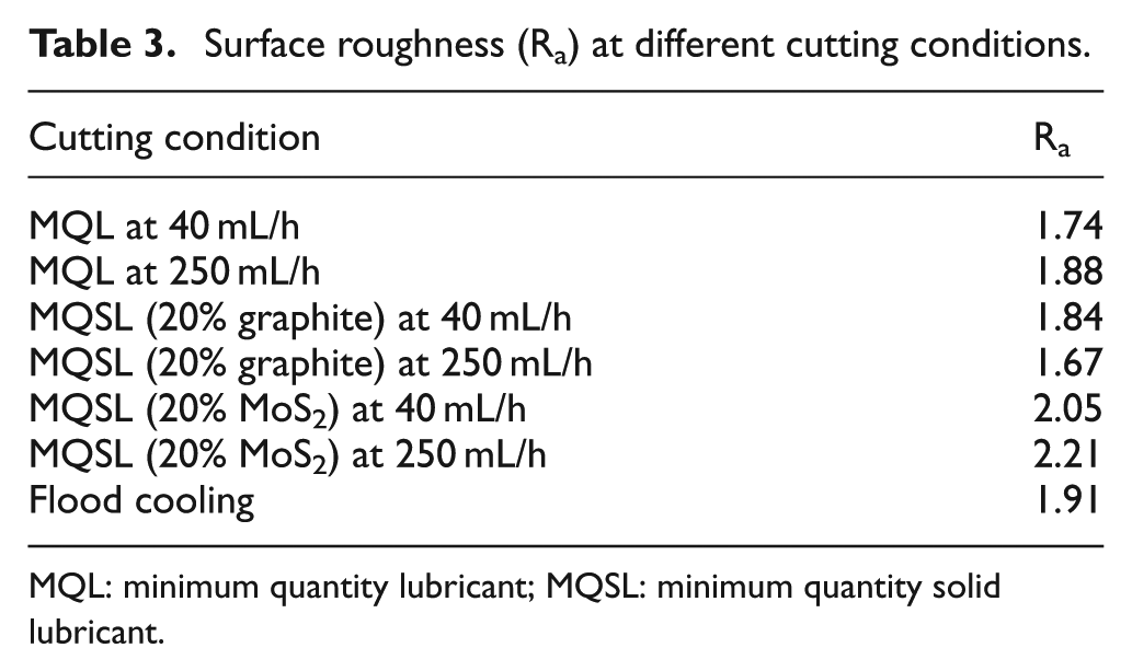
MQL: minimum quantity lubricant; MQSL: minimum quantity solid lubricant.
Yazid et al. 4 have studied the machinability of the same material investigated in this work (Inconel 718) using single-layer PVD TiAIN-coated carbide cutting tools (CNMG 120408QM 1105). The machining parameters were varied under the lubri-cooling atmosphere (dry, MQL at a constant flow rate of 50 and 100 mL/h – without any solid lubricant), and cutting speeds (90, 120, 150 m/min), feed rates (0.10, 0.15 mm/rev) and depth of cut (0.30, 0.50 mm). Research finding reveals a slight improvement in surface roughness when the cutting speed increased from 90 to 150 m/min. It has also revealed that there are no significant changes in the surface roughness when the flow rate of the MQL technique was increased from 50 to 100 mL/h, except for the cutting speed 150 m/min.
It can be concluded here that the substantial improvement in the surface quality when using MoS2 can be attributed to its good lubricating action (reducing friction) under the severe conditions encountered at the chip–tool–workpiece interfaces during machining of hard-to-machine material such as Inconel 718. Reddy and Rao 12 also observed an average of 23% reduction in the surface roughness with MoS2 solid lubricant during machining of medium carbon steel as compared to application of wet cutting and 43% of reduction when compared to dry condition.
In fact, the surface roughness is more dependent on the lubricant and cooling actions of the fluids. If lubricant action prevails at machining zone, the material will have higher shearing resistance, changing the dynamic system and affecting the surface roughness values depending on the machine tool rigidity. 22 This phenomenon ultimately leads to the formation of chip smoothly and results in good surface roughness.
Machining forces
The machining force components are good indicators of the performance of any machining process which can be attributed mainly to the formation of a thin film of lubrication and that reduces the shear strength of the material at the machining zone, so that machining becomes easier. They are dependent on several parameters such as workpiece material properties, tool geometry, tool material, cutting fluid properties, method of application and cutting conditions. 12 Figure 3 shows the behaviour of the average of the three force components during machining under several environmental cutting conditions studied. The results show that for the cutting conditions studied, the use of a solid lubricant did not cause a reduction in the machining force components. However, there was a marginal increase in the feed force when the flow rate was changed from 40 to 250 mL/h.
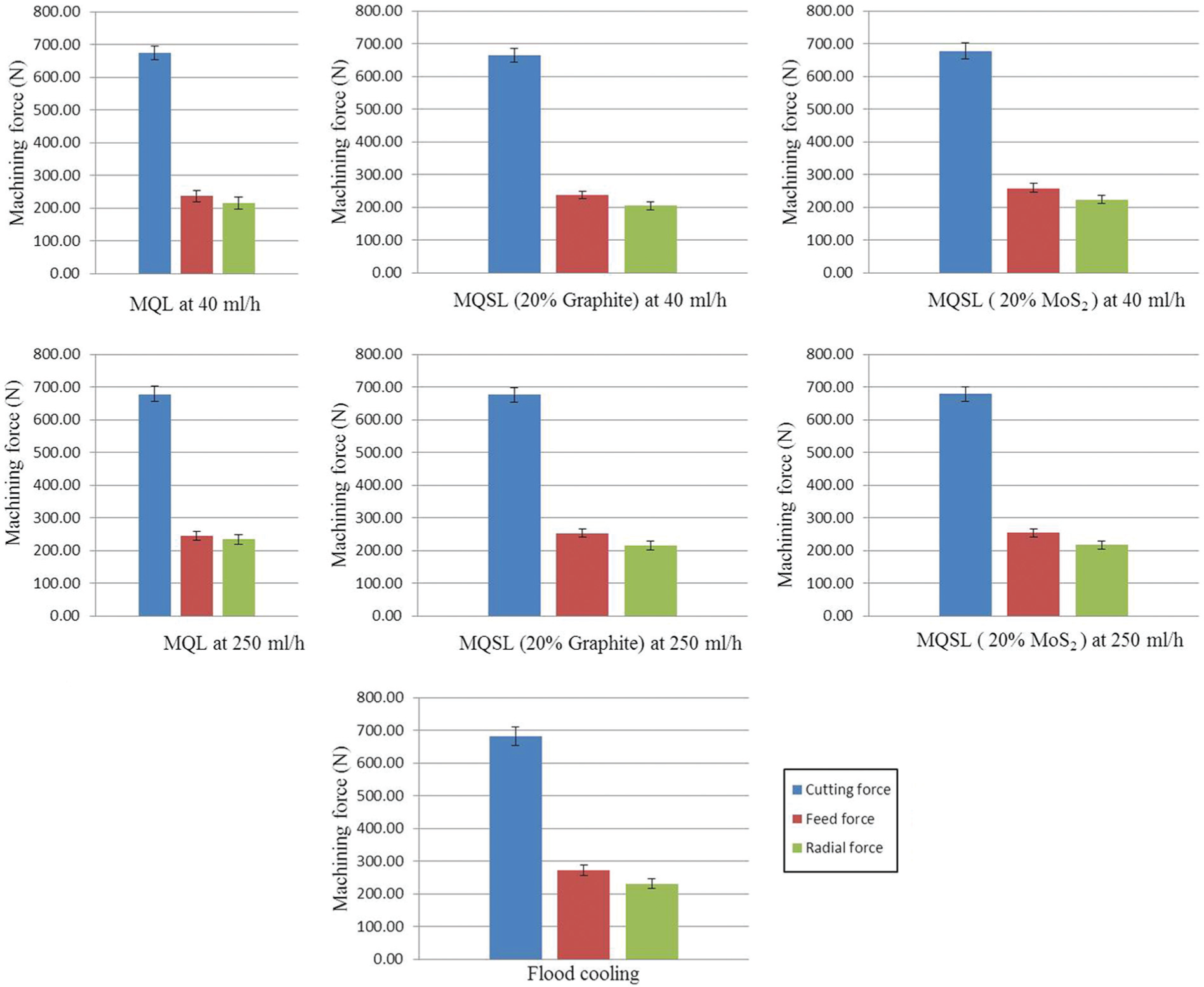
Machining force components at cutting speed = 100 m/min, feed = 0.15 mm/rev and depth of cut = 1.5 mm under different lubri-cooling conditions.
When compared to flood cooling, the oil mixed with solid lubricant presented an average reduction in the feed force of 7%, with emphasis on MoS2 at 40 mL/h that showed 12% of reduction. This is an indication that the MQSL (MoS2 at 40 mL/h) technique presented the better lubricant action, allowing the chip to slip easier on to the rake face of the tools whereas the conventional flood cooling condition may present better cooling action. This cooling action increases the shear strength of the workpiece and results in increase in the machining forces. The lubricants act predominantly and contribute to reduce the friction and the chip–tool–workpiece contact areas, allowing higher cutting speeds, better surface roughness and higher tool lives. However, their efficiency will depend on their ability to penetrate into the contact zone in a very short period of time available and to form a film with shear resistance lower than that of the workpiece material. 22
Assessment of tool life
The assessment of tool life during machining of Inconel 718 alloy has been carried out until the end of their lives stipulated by the tool life criterion (VBBmax = 0.6 mm) to allow comparisons among the several lubri-cooling conditions tested. Figure 4 presents the average values of the tool lives for each of the lubri-cooling conditions. The bar graphics of Figure 4 show that the average of the tool lives under molybdenum disulphide solid lubricant–assisted machining condition yielded satisfactory results as compared to the other MQL conditions including graphite solid lubricant–assisted machining. The average increase in tool life was around 15% for the flow rate of 40 mL/h and approximately 12% for 250 mL/h. In order to conclude the results, the significance of variance has been calculated (FCal = 3.17, FTable = 2.97). It has been concluded from the analysis of variance (ANOVA) that the significance of change in flow rate of MoS2 from 40 and 250 mL/h is appreciable.
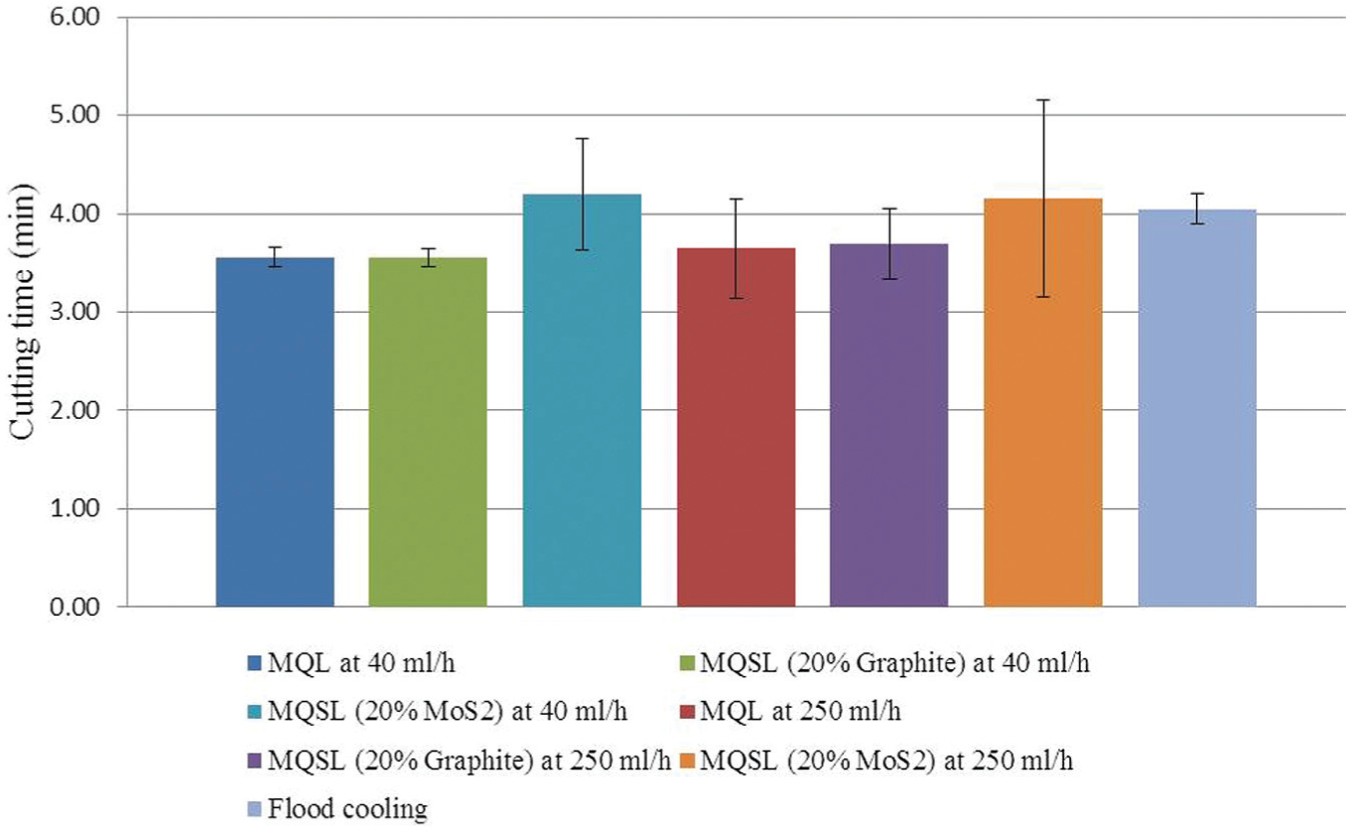
Tool lives at cutting speed = 100 m/min, feed = 0.15 mm/rev and depth of cut = 1.5 mm under different lubri-cooling conditions.
When compared to the conventional flood cooling, the MQSL of oil mixed with graphite and MoS2 gave an average increase in tool lives of only 4%. The substantial improvement can be attributed to the fact that both graphite and molybdenum disulphide are well known for their good lubricant properties due to their structure being formed by layers bonded by Van der Waals forces that are relatively easy to slip against each other. However, for the cutting conditions studied, only MoS2 showed better lubrication action giving satisfactory results; the solid lubricant melts and smears creating a thin lubricating film on the rake face of the tool. The increase in tool lives can be attributed to the formation of the effective coating film of lubricant on the tool surface that reduces friction 14 and, combined with an amount of cooling action, thereby reduces temperature and tool wear. In this case predominantly, crater and flank wear with involvement of attrition, abrasion and chemical wear mechanisms as well as chippings and spalling are dependent on both lubrication and cooling action. 17 Considering that the surface roughness and feed force were better with MQSL, MoS2-assisted machining was used; it is tendentious to say that the cooling action here (in tool life) was more important than the lubricant action. The better result with the low flow rate of 40 mL/h corroborates with these findings.
After the tool life tests, wear of the tool has been analysed using scanning electron microscope (SEM). In view of observation of great amount of adherent work materials on the tool surface, they were embedded in hydrochloric acid (HCl) for 48 h to remove them and allow clear observation of the worn areas. Figures 5–8 show details of the SEM analysis. The patterns of the worn area of the tools are similar for all environmental cutting conditions used, with the appearance of maximum flank wear and crater wear. Sometimes, this appearance is very close to the cutting edges. The position of the maximum flank wear varies from the corner radius of the tool until the end of the depth of cut. Chipping and plucking off phenomena are also observed.
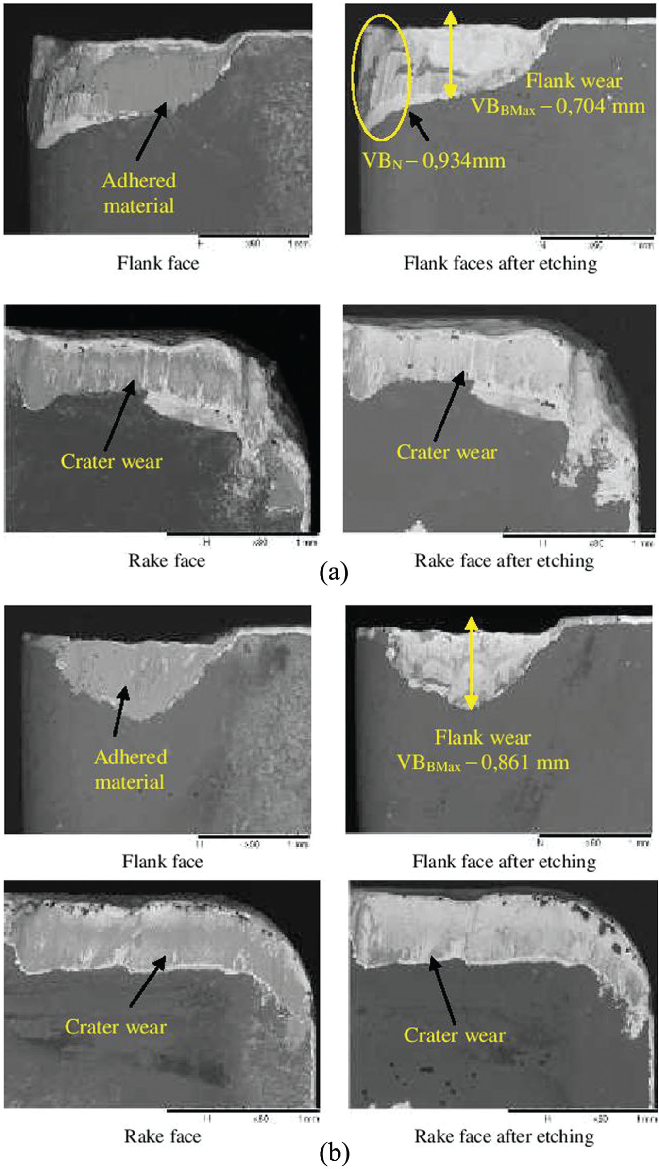
SEM overview of the worn areas of the tools after machining until the end of their lives at cutting speed = 100 m/min, feed = 0.15 mm/rev and depth of cut = 1.5 mm under (a) MQL at 40 mL/h and (b) MQL at 250 mL/h.
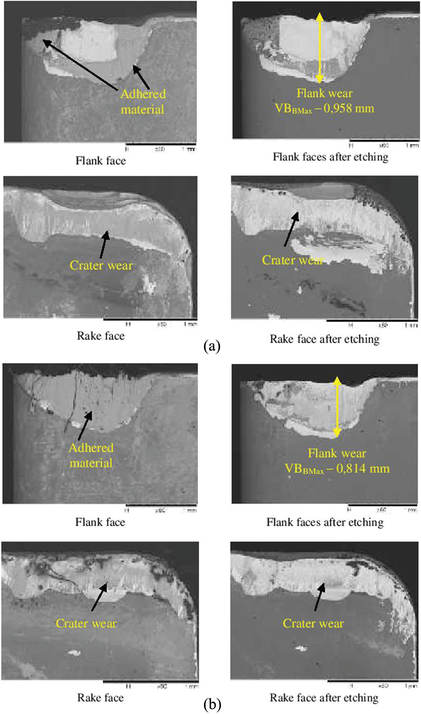
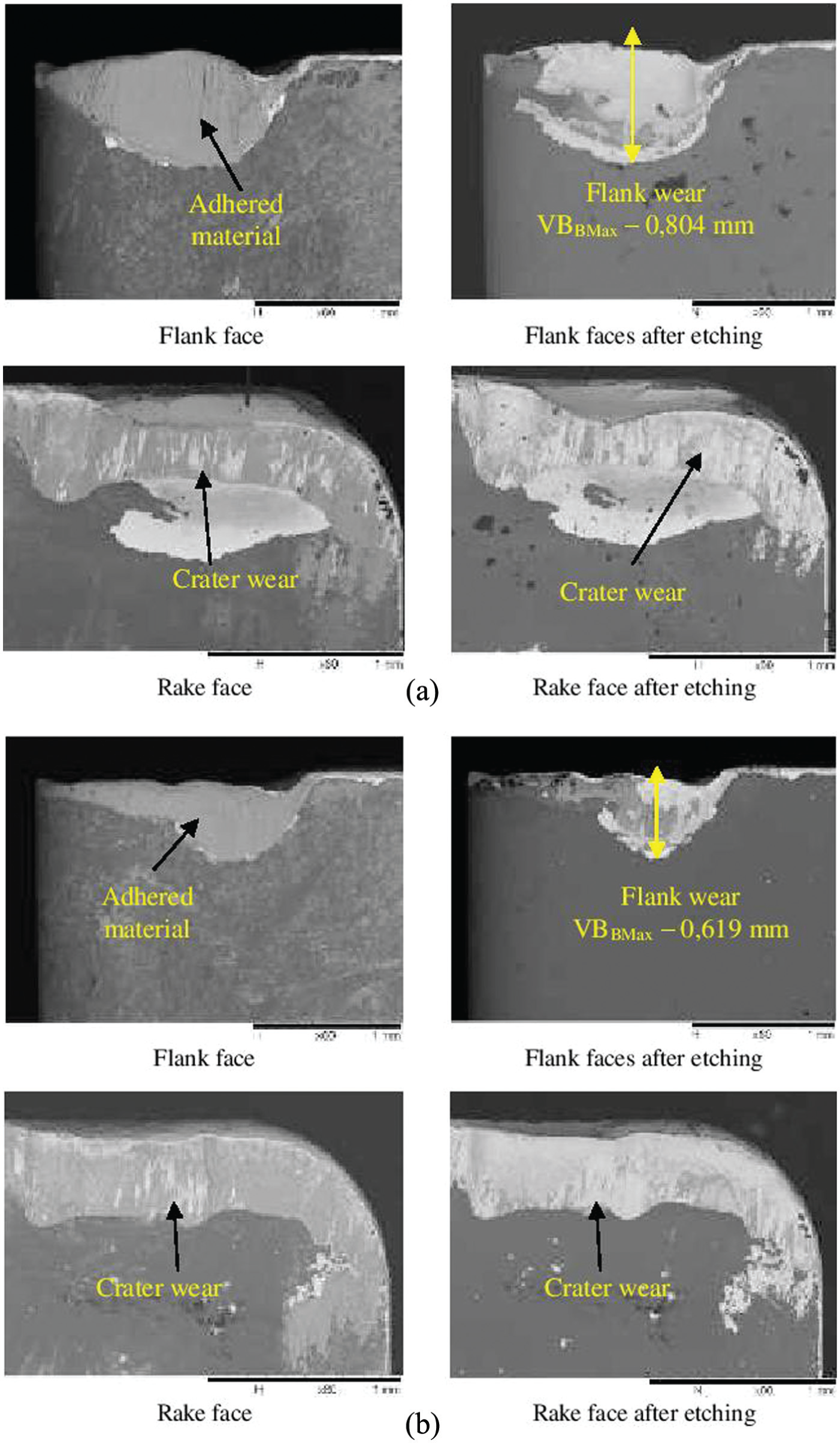
SEM overview of the worn areas of the tools after machining until the end of their lives at cutting speed = 100 m/min, feed = 0.15 mm/rev and depth of cut = 1.5 mm under (a) MQSL (20% graphite) at 40 mL/h and (b) MQSL (20% graphite) at 250 mL/h.
SEM overview of the worn areas of the tools after machining until the end of their lives at cutting speed = 100 m/min, feed = 0.15 mm/rev and depth of cut = 1.5 mm under (a) MQSL (20% MoS2) at 40 mL/h and (b) MQSL (20% MoS2) at 250 mL/h.
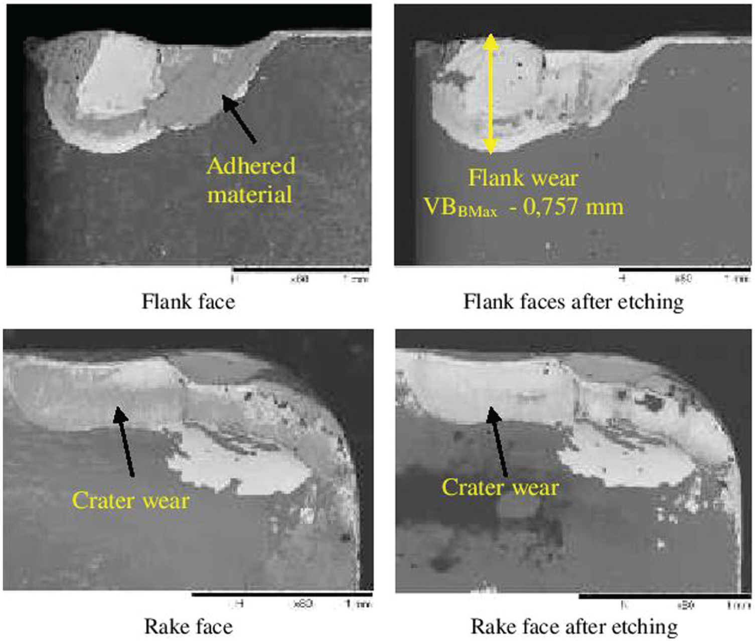
SEM overview of the worn areas of the tools after machining until the end of their lives at cutting speed = 100 m/min, feed = 0.15 mm/rev and depth of cut = 1.5 mm under flood cooling of 4.5 L/min.
Tool wear analysis
Wear of tools is inevitable due to rubbing action between work material and tool edge along the machining surfaces, which causes diffusive, abrasive and adhesive wear mechanisms. To evaluate the performance of MQSLs in machining of nickel-based superalloy, tool life tests were performed; the solid lubricant melts and smears, forming a thin layer of lubricant between the chip and the rake face of the tool. It can be seen that in general the curves of Figure 9 have the same behaviour for all cutting conditions used. However, when comparing the conditions of lubrication used, the molybdenum disulphide showed a significant improvement compared to MQSL (graphite) and MQL without addition of solid lubricant and conventional fluid application. This is probably due to greater adhesion of molybdenum disulphide near the cutting zone and thereby reducing friction in the chip–tool and work–tool interface part.
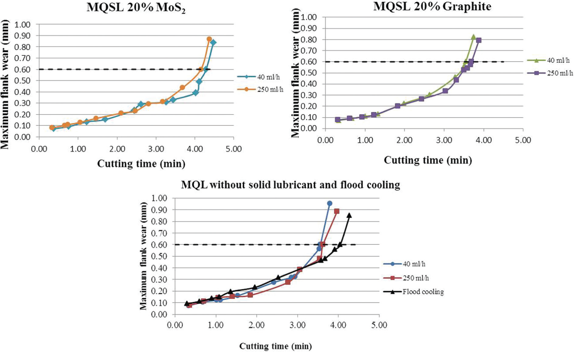
Variation in maximum flank wear with respect to cutting time at cutting speed = 100 m/min, feed = 0.15 mm/rev and depth of cut = 1.5 mm under different lubri-cooling conditions.
Furthermore, the use of MQSL:graphite in the mixture showed no significant difference when compared with the MQL with no solid lubricant. The results showed that the use of the technique MQSL is favourable when molybdenum disulphide is used in the mixture. It was also observed that low flow rate of MQSL with molybdenum disulphide showed better results.
Figures 10 and 11 show details of the worn areas of the tools used with graphite and molybdenum disulphide at the flow rate of 250 mL/h, respectively. These details can be linked to the wear mechanisms involved, as stated by Trent and Wright. 23 The smooth worn areas seen at the tool surfaces are the indication of occurrence of chemical wear at atomic levels (diffusion). In the more rough portions of the worn areas, particles of the tool were plucked off and it indicates that attrition mechanism took place. The parallel ridges observed configure the presence of abrasion wear mechanism. Chipping and spalling were also observed. Diffusion is more temperature dependent than attrition and abrasion, and therefore, cooling action is more important during machining of hard-to-machine material. Attrition and abrasion depend more on the active lubricant area. 24 The better performance of the molybdenum disulphides is a result of the combination of both actions. The presence of adhered MoS2 on the tool surface of Figure 11 is a clear indication that the lubricant action is in play.
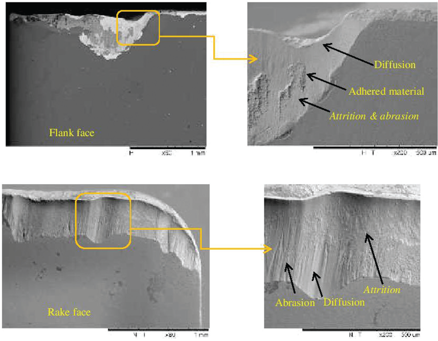
Details of the worn area of the tool used for cutting Inconel 718 applying MQSL:oil mixed with 20% of graphite at 250 mL/h.
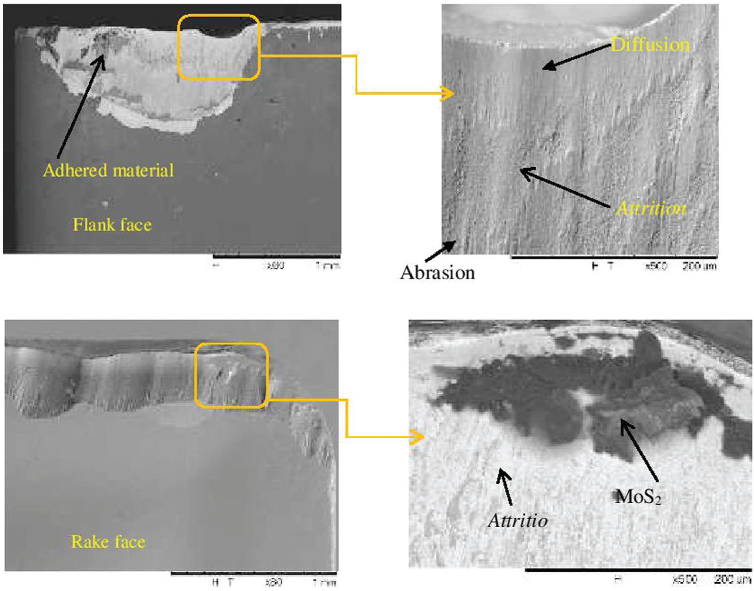
Details of the worn area of the tool used for cutting Inconel 718 applying MQSL:oil mixed with 20% of MoS2 at 250 mL/h.
Micro hardness
Micro hardness measurements were measured at various points in the cross section of the machined surfaces. Figure 12 shows the results of micro hardness for all cutting conditions studied. In general, it was observed that there was a significant decrease in hardness of the material and all surface conditions show a similar curve gradually falling down to a depth of about 120 µm below the machined surface. The present findings are in good agreement with the results of the research by Pawade et al. 25 machining the same material – Inconel 718. Application of fluid in abundance (flood cooling) showed the lowest value of surface hardness and the MQL system (without solid lubricant) results in higher hardness when compared with other environmental conditions.
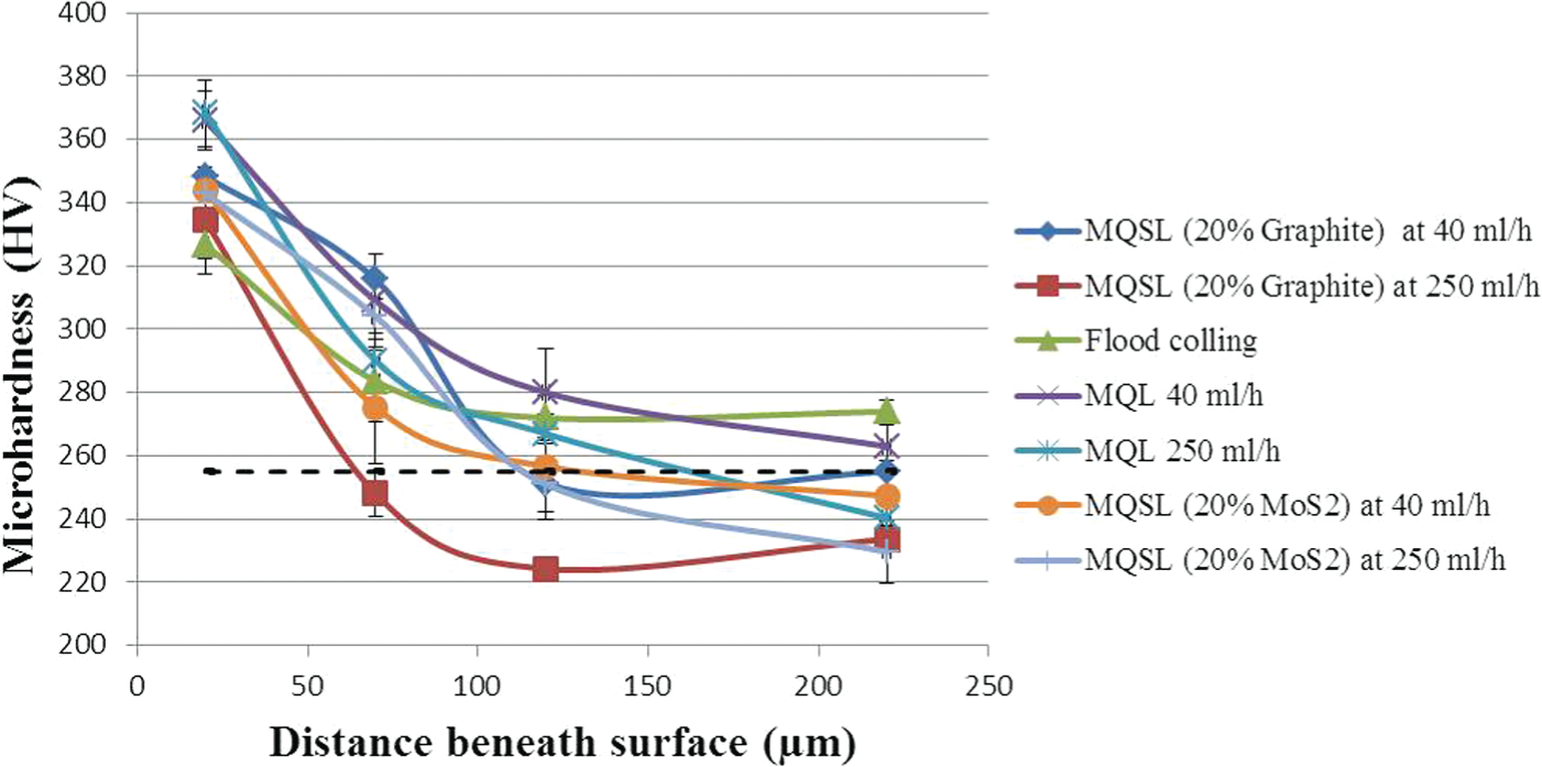
Variation in micro hardness with distance beneath the machined surface at cutting speed = 100 m/min, feed = 0.15 mm/rev and depth of cut = 1.5 mm under different lubri-cooling conditions.
There has been no variation in micro hardness of the base material between 120 and 220 µm beneath the surface. This can be due to the variations in positioning of face-centred cubic (FCC) structure of nickel in different crystalline grains of the basic material. It can also be observed that when compared with machining processes by the conventional technique with MQSL and MQL technology, the addition of a solid lubricant (graphite and molybdenum disulphide) to the cutting fluid showed a slight reduction in hardness, indicating that there was improved lubrication during the machining process facilitating shearing of the material and reducing work hardening, and these findings can be clearly seen from micro structure photographs of the Inconel 718 specimens illustrated in Figure 13 where the hardness of the material returns to their initial condition at lower depths of cut.
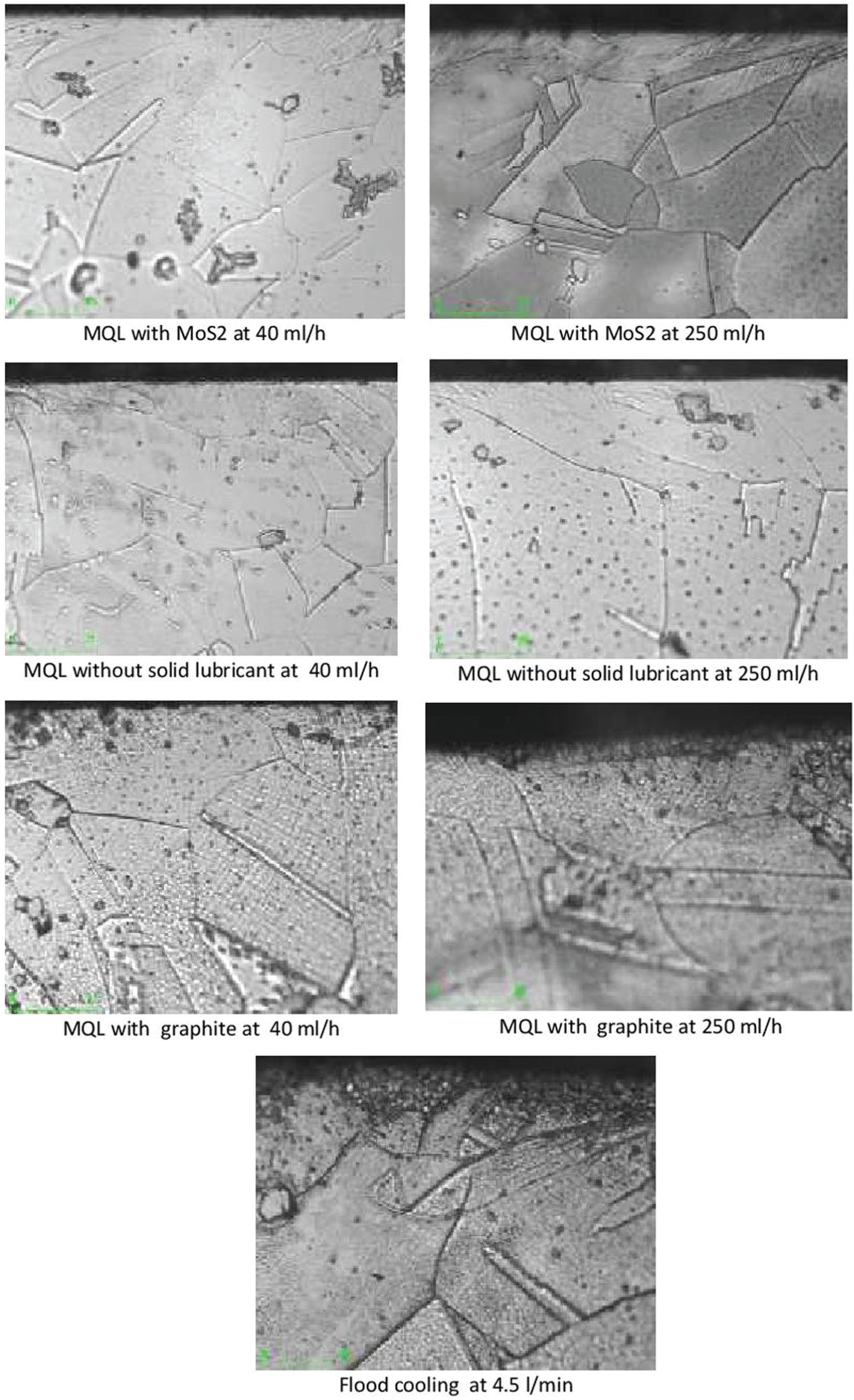
Micro structure photograph of the Inconel specimens at cutting speed = 100 m/min, feed = 0.15 mm/rev and depth of cut = 1.5 mm under different lubri-cooling conditions.
Conclusion
An attempt has been made in developing economical in-house MQSL: MQSL experimental set-up aiming to improve the machinability of hard-to-cut Inconel 718 alloy; the formation of thin film of lubrication on the rake face of the tool reduces the frictional forces between the tool and chip, which subsequently reduces the temperature developed and prevents the tool wear which further leads to substantial improvement in cutting performance. If the fluids are applied precisely to the machining zone, improved results can be expected. Within the selected machining experimental domain, the influence of MQSL in terms of machinability parameters such as cutting forces, tool wear, micro hardness, micro structure and surface roughness of machined surface has been demonstrated during machining of Inconel 718 alloy, and MQSL results were compared during machining with other conditions of MQL and flood-assisted machining. The results demonstrate that the effectiveness of the use of MQSL was found to be 13% superior in reducing friction and heat generation at work–tool interface and contribute to the decrease in the tool wear. Cutting forces and surface roughness of the machined part showed significant variation in tested cutting conditions.
The main findings of this work are as follows:
The increase in the flow rate applied by the MQSL technique did not show improvements on the surface roughness of the Inconel 718 workpiece. MQSL with mixture of MoS2 with oil showed significant improvement in surface quality in comparison with MQSL with mixture of graphite with oil, MQL and also the other conventional flood cooling applications. The decrease in surface roughness under MoS2 solid lubricant–assisted machining can be attributed to the reduction in friction due to the layered lattice structure of these lubricants and inherent lubricating properties of the solid lubricants even at extreme temperatures.
No appreciable significant differences were detected in the cutting force with both the solid lubricants in comparison with the other machining conditions. However, the feed force was marginally reduced (average of 7%) with solid lubricant–assisted machining compared to MQL and flood cooling. In addition, the MoS2 solid lubricant has performed much better than the graphite solid lubricant by an average of 12% reduction in the feed force at the flow rate of 40 mL/h. This fact can be attributed due to the presence of effective MoS2 film existing on tool face, thereby the friction at the tool–chip interface zone is reduced and thus, the cutting force is decreased.
The highest tool lives were promoted by the MQSL application (oil mixed with molybdenum disulphide) even when compared to the MQL, MQSL application (oil mixed with graphite) and conventional flood cooling. No significant differences were found in tool lives when MQSLs with 0% and 20% of graphite were tested. Application of MQSL (oil mixed with molybdenum disulphide) in the machining zone results in the reduction in flank wear; addition of MQSL within the contact interface causes low rate of friction coefficient, sliding action and low shear resistance.
The dominant wear mode mechanisms involved in all the environments (MQSL, MQL and conventional flood cooling) considered are attrition, abrasion and diffusion wear mechanisms as well as chipping and spalling took place during cutting. The pattern and mechanisms of the wear were the same in all the environments involved.
Footnotes
Declaration of conflicting interests
The author(s) declared no potential conflicts of interest with respect to the research, authorship, and/or publication of this article.
Funding
The author(s) disclosed receipt of the following financial support for the research, authorship, and/or publication of this article: The work has been carried out under the financial support of the Department of Science and Technology (DST), India, through sponsored project – SR/S3/MERC/031/2012.