
Abstract
A novel severe plastic deformation technique entitled rubber pad tube straining is proposed suitable for manufacturing of high-strength ultrafine-grained and nanostructured thin-walled cylindrical tubes. A punch with a convex portion in the middle is pressed down into a tube constrained with a hollow cylindrical rubber supported by a rigid cylinder. Tube diameter increases and decreases incrementally when the punch is pressed down, and the rubber pressure pressed back the tube diameter to its initial size. This process was performed on a commercially pure aluminum tube. Finite element results revealed that the equivalent plastic strain of about 1 could be reached at the end of the first cycle of rubber pad tube straining while having a good strain homogeneity along the thickness and length. Experimental results showed that the yield and ultimate strengths were increased to about 172 and 182 MPa from the initial values of about 80 and 128 MPa, respectively. Also, the hardness was increased to ∼55 HV from ∼44 HV.
Introduction
During last two decades, considerable efforts have been made for producing high-strength ultrafine-grained (UFG) materials using severe plastic deformation (SPD) methods. 1 Equal channel angular pressing (ECAP), 2 high-pressure torsion (HPT), 3 repetitive forging, 4 accumulative roll bonding (ARB) 5 and cyclic extrusion compression (CEC) 6 are available SPD methods for deforming bulk materials. These processes change the grain size to UFG and nanostructured range due to the application of severe plastic straining. Considering the need for high strength to weight tubes in different industries, efforts to produce UFG and nanostructured tubular using the SPD are being progressed. Tóth et al. 7 proposed high-pressure tube twisting (HPTT) as an SPD method based on HPT process. This process imposes high shear strains under high hydrostatic pressure while needs very high axial force and rotational torques. Besides, it has some other restrictions such as lower homogeneity because of large strain gradient of the tube wall. Other SPD methods of tubular components such as tubular channel angular pressing (TCAP) and parallel tubular channel angular pressing (PTCAP)8–10 also have some other limitations which make them not suitable for deforming long and thin-walled tubes. These methods used hollow cylindrical punches with the thickness identical to the tube thickness. Yielding and buckling of the hollow cylindrical punches makes the methods suitable for processing of only thick and short tubes. Mohebbi and Akbarzadeh 11 presented the accumulative spin-bonding (ASB) method that has the main problem of interlayer defects. So, there is not a suitable method for processing of thin-walled tubes. In this article, a new SPD method for producing UFG thin-walled tubes using a solid punch and a rubber pad die is presented. For the implementation of the method, commercially pure aluminum was processed. Also, experimental and numerical investigations are carried out.
Principles of rubber pad tube straining
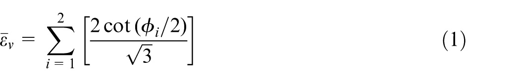
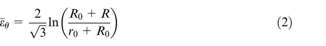
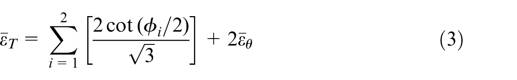
The schematic of rubber pad tube straining (RPTS) process and the die setup are shown in Figure 1. According to Figure 1, at the beginning of the process, the tube is placed inside the hollow cylindrical rubber and then the tube and rubber are placed into the gap between the die and a movable mandrel. The set is constrained using upper and lower die shoes. The mandrel is pressed down until the convex part reaches the edge of the tube as shown in Figure 1(a). The tube is locally deformed by the mandrel as shown in Figure 1(b) and the diameter of the tube increases. When the mandrel is pressed down, the deformation zone incrementally moves along the tube length. During the deformation, the rubber pressure pushed back the tube on the mandrel to keep the tube diameter constant in the regions before and after the deformation zone. Finally, the mandrel reaches the end of the tube as shown in Figure 1(c). In each cycle, the tube experiences shear deformation in two shear zones of I and II shown in Figure 1(d). The mandrel can be moved repeatedly up and down for achieving additional strains without changing the dimension. To calculate the amount of equivalent plastic strain, the procedures used in Faraji et al.
8
for TCAP process could be implemented because the deformation behavior and die geometry is almost same. During the RPTS process, shear strains
12
according to equation (1) as a result of the angled zone and also tensile and circumferential compression strains
13
according to equation (2) as a result of diameter increase are achieved. The total equivalent plastic strain could be calculated by summation of both equivalent strains as shown in equation (3). Considering two shear deformations, and existence circumferential strains besides shear ones in RPTS, the exact amount of the overall strain
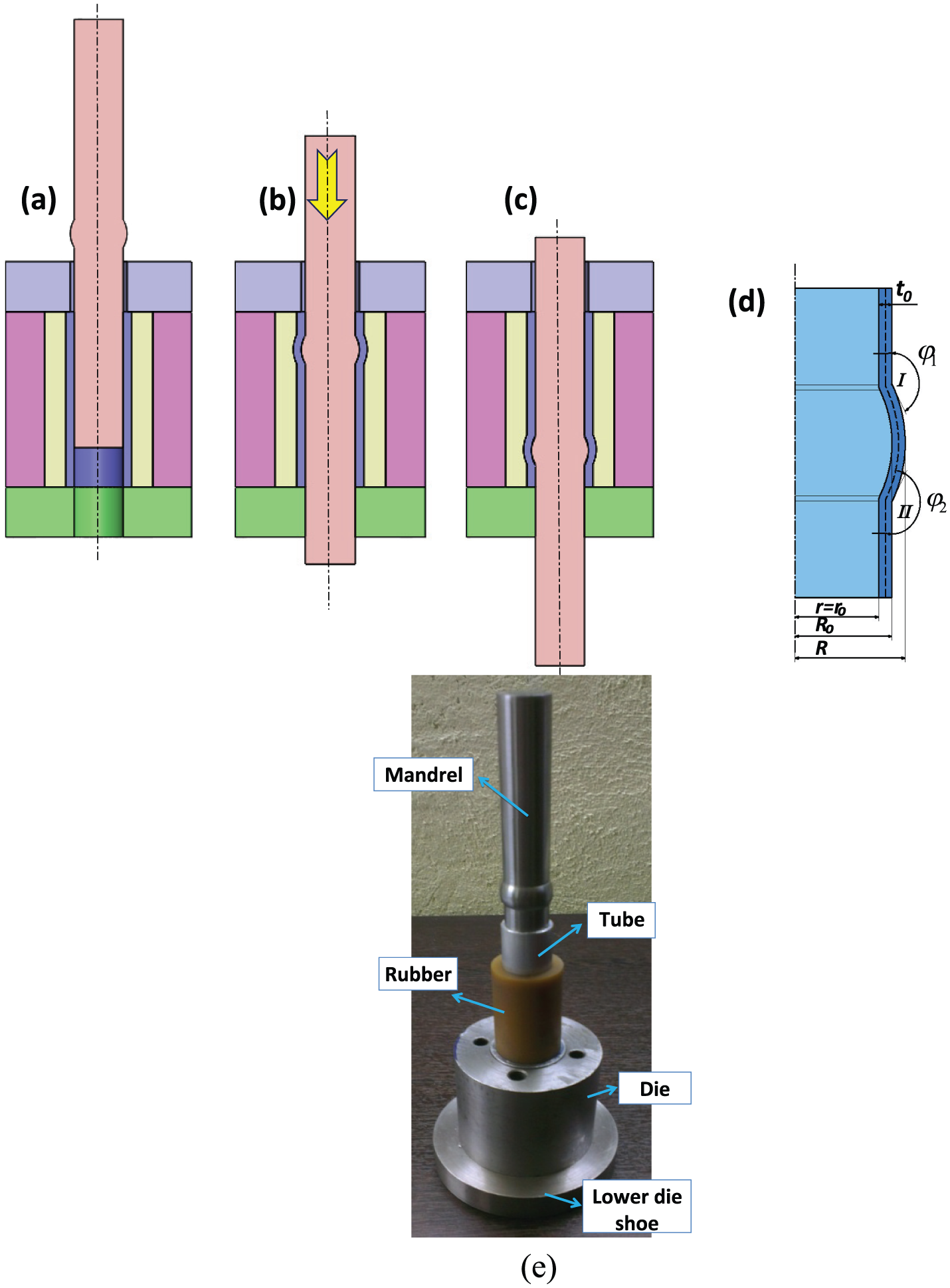
Schematic of RPTS process: (a) initial state, (b) during the process, (c) end of the process, (d) deformation region and the die parameters and (e) RPTS die setup.
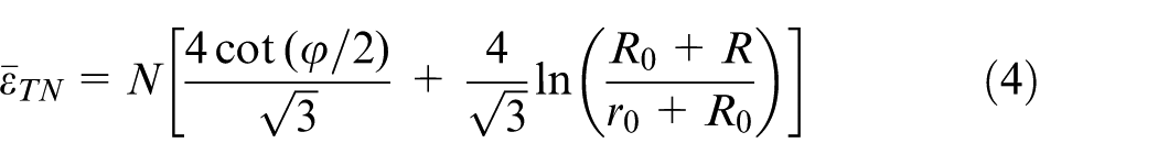
Considering the parameters shown in Figure 1(d) and Table 1, equation (1) results in
Die parameters and their values.
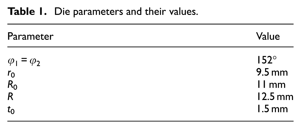
According to equation (4) and also the parameters listed in Table 1, the amount of total equivalent plastic strain of RPTS after each cycle is about 1.2.
Finite element procedures
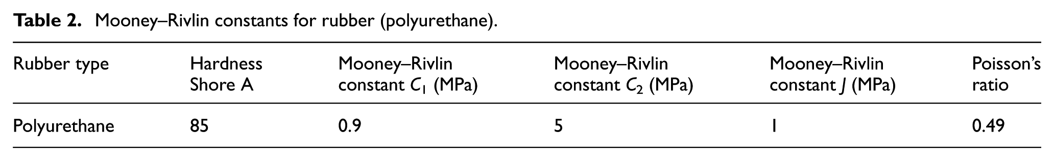
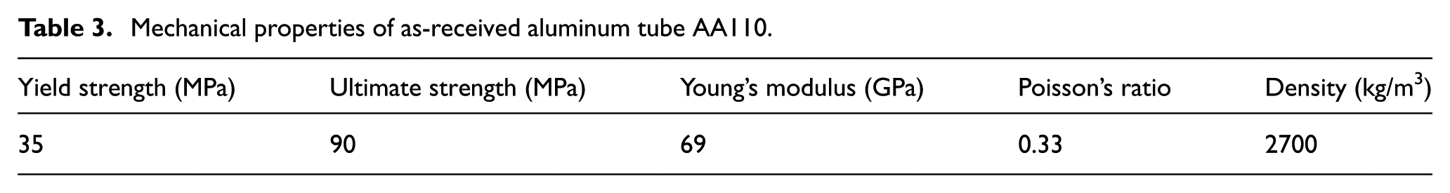
ABAQUS explicit finite element (FE) code was used to do the FE simulations. Four node plane strain elements (CAX4R) are applied for meshing the aluminum tube and rubber. Friction between the tube, rubber and mandrel is considered as 0.1. 14 The axisymmetric two-dimensional (2D) FE meshed model including the rigid mandrel, deformable tube and rubber is shown in Figure 2. Modeling of the rubber is crucial because of its deformation and the mutual influence on the deformation of the aluminum tube. Rubbers are materials with high flexibility while having small incompressibility. So, linear elastic theories could not be applied to them. For this reason, providing a comprehensive model to express its deformation behavior is difficult and requires complex multi-parameter mathematical models. In this work, polyurethane rubber with a density of 1700 kg/m3 and hardness of 85 Shore A was used. For nearly incompressible materials with a high elasticity property (Poisson’s ratio is about bigger than 0.475), such as materials similar to rubber, hybrid elements should be used. 15
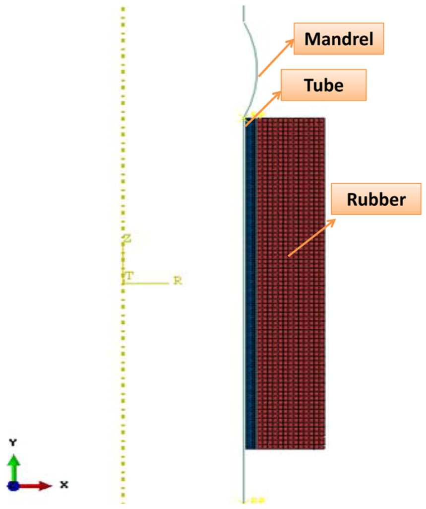
FE model including meshed parts.
Hyperelastic materials could be modeled based on the strain energy (W) which expresses the strain energy stored per unit volume. Several theorems are available in ABAQUS for modeling of such materials. Mooney–Rivlin equation was used which was previously used successfully to predict the behavior of hyperelastic materials. 16 Mooney–Rivlin equation is based on the assumption that the free energy of any homogeneous, isotropic material can be expressed by a set of infinite series of the three strain invariants. First-order expansion of Mooney–Rivlin model is shown as follows
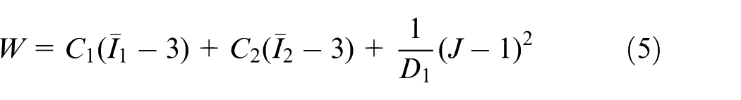
where
Mooney–Rivlin constants for rubber (polyurethane).
Mechanical properties of as-received aluminum tube AA110.
Experimental methods
The commercially pure aluminum AA1100 tube of 21 mm in outer diameter, 1.5 mm of thickness and 70 mm in length was used. Samples were annealed at 450 °C for 1 h before processing. A recrystallized microstructure of as-received material with an average grain size of about 160 µm is shown in Figure 3. A die setup shown in Figure 1(e) was manufactured. Experiments with a broad range of rubbers including silicone, soft polyurethane and polyvinyl chloride (PVC) rubbers were performed and the results are shown in Figure 4. The experiments done with the use of the hard polyurethane rubber was successful. Then, the RPTS process was applied through one pass and three passes. The experiments were performed at room temperature at a pressing speed of 10 mm/min. Tensile properties were achieved through a tensile test at a strain rate of 10−4 s−1 at room temperature. Microhardness tests were measured with a load of 100 g applied for 8 s.
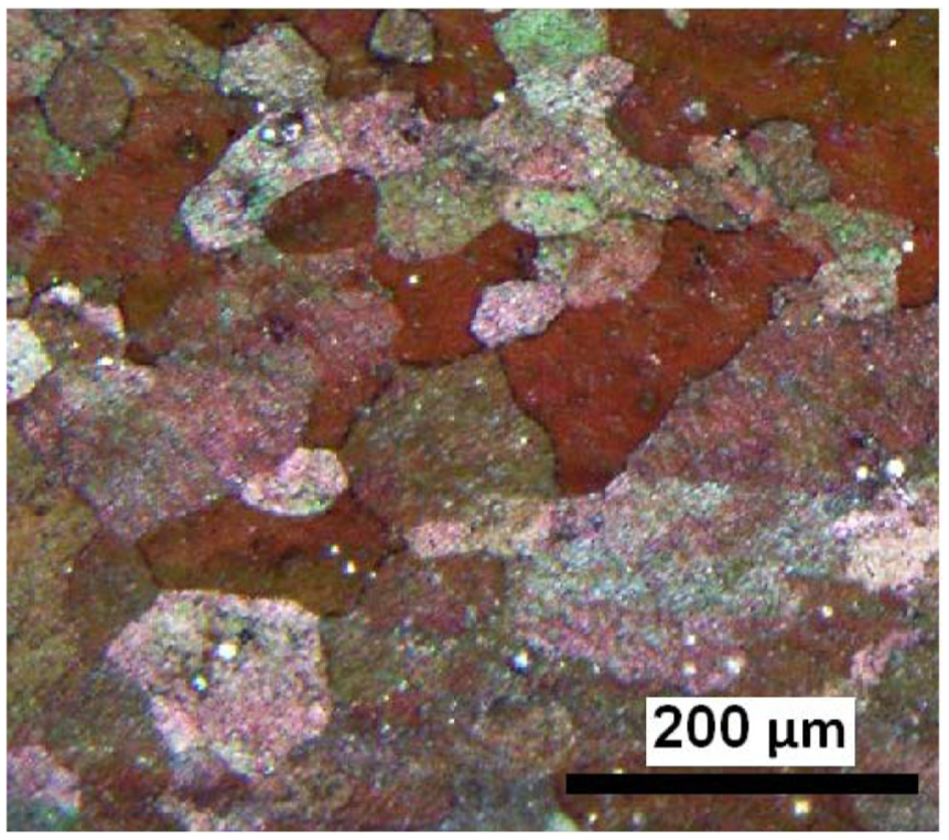
A recrystallized microstructure of the unprocessed material.
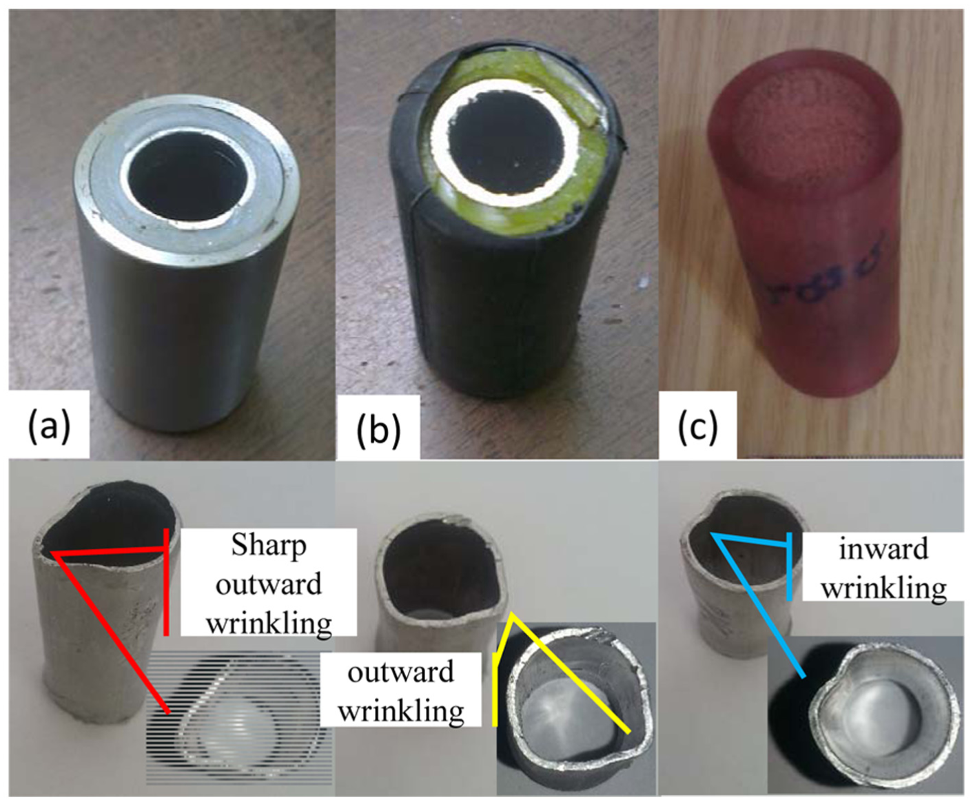
Different types of rubbers used in unsuccessful tests: (a) silicon, (b) soft polyurethane and (c) PVC.
Results and discussion
Equivalent plastic strain contours of the RPTS-processed tubes through a different number of passes are shown in Figure 5(a) and (b). As indicated, with the increasing number of passes, the amount of equivalent plastic strain is increased. Equivalent plastic strain curves along the processed tube thickness are shown in Figure 5(b). As can be seen, the strain after the first pass, which is about 1, increases to about 2.3 after third pass. It could be anticipated that the equivalent plastic strain after third pass should be about 3. The difference may be related to the deformation geometry that affects the enhanced mechanical properties of the Al tube and the constant properties of the rubber. Also, the value of strain in the inner region of the tubular workpiece was higher than that of the outer part. The strain homogeneity is decreased by an increase in the number of RPTS passes. According to equation (3), the amount of total equivalent plastic strain is 1.2 while it is about 1 from FE results. The difference between FE and analysis is because of corner gap formation in FE modeling 17 which leads to increase in the curvature angles and consequently to decrease in the strain level. The difference is increased in the processed sample in a higher number of passes compared to the one pass processed sample which is related to change in mechanical properties. Also, the curvature and corner angles may vary in a different number of passes. Also, the friction effect which was not considered in the analytical method may be one of the other sources of errors in strain estimations.
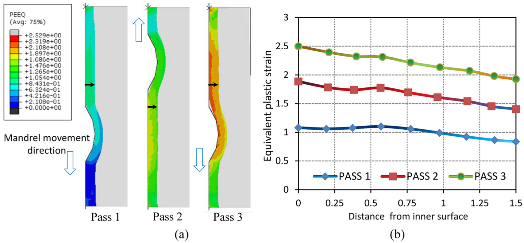
(a) Equivalent plastic strain contours of the RPTS-processed tubes during different passes and (b) strain distribution curves along the tube wall.
In addition to the RPTS simulation, TCAP process with the same die parameters was simulated, and the forces were compared. FE results showed RPTS process has less amount of force compared to TCAP process as shown in Figure 6. This is because both inner and outer surfaces of the tube are frictional contact surfaces in TCAP process while the only inner surface of the tube is frictional contact surface in RPTS process. In other words, only the inner surface has relative movement with the mandrel while the outer surface does not have a relational movement with the rubber (which plays die role).
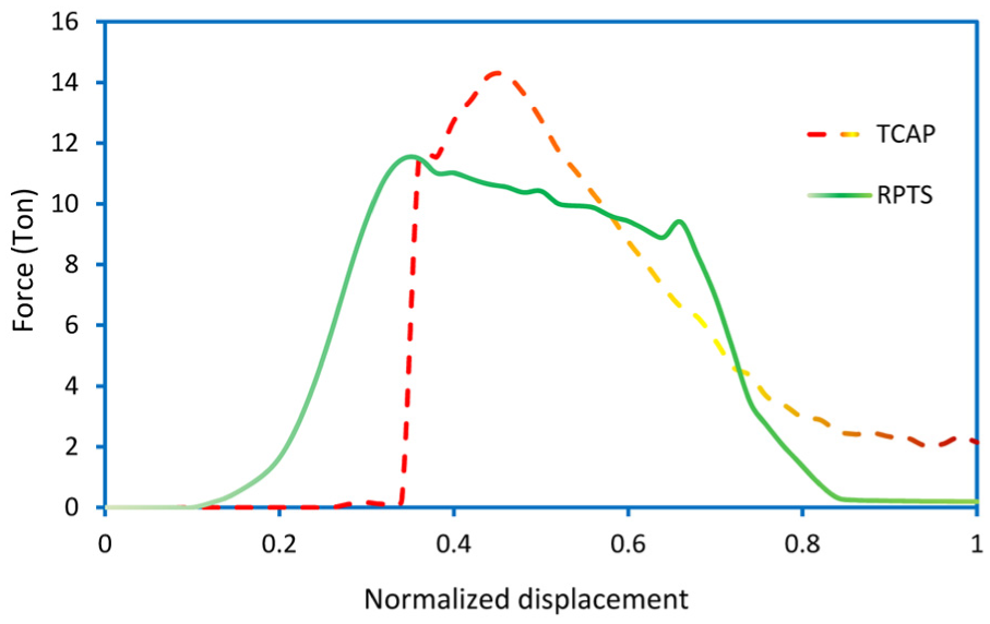
Force–normalized displacement diagram for RPTS and TCAP processes.
Besides needing higher process load, TCAP process uses hollow cylindrical punches with the thickness identical to the tube thickness while RPTS process uses solid mandrel as punch. Yielding and buckling of the hollow cylindrical punches makes the TCAP method suitable for processing of only thick and short tubes while RPTS process does not have this limitation because of the use of a solid punch. Considering the force required for RPTS and TCAP process (Figure 6) and also corresponding punch cross-sections showed that the stresses of about ∼1520 and ∼400 MPa are applied on the punches, respectively. So, processing of Al tube with dimensions used in this work by TCAP process needs a very high-strength punch (min yield strength = 1520 × 1.5 (safety factor)) material. This means that TCAP processing of the Al tube processed by RPTS (current work) is very hard or almost impossible.
Figure 7 shows unprocessed and RPTS-processed tube at the end of the first pass. One of the characteristics of the SPD processes is remaining the cross-section of the sample constant before and after the process. It was observed that the cross-section of the processed tube is almost identical to that in starting though the lower end part of the tube have a larger diameter compared to the upper region. At the end of the RPTS process, when the mandrel reaches its maximum stroke, lower die shoe (Figure 1) is unassembled from the die setup. Then, the mandrel and tube release from the rubber. So, there is no back pressure to decrease the tube diameter. This leads to the higher diameter of the tube at the bottom part in comparison with the upper regions. Thickness distribution along the peripheral and longitudinal direction of unprocessed and RPTS-processed tubes is shown in Figure 7(c) and (d). This figure shows that the thickness variation after and before the process is almost negligible. Also, a round shape of the processed tube shows that the shape remains constant after RPTS processing.
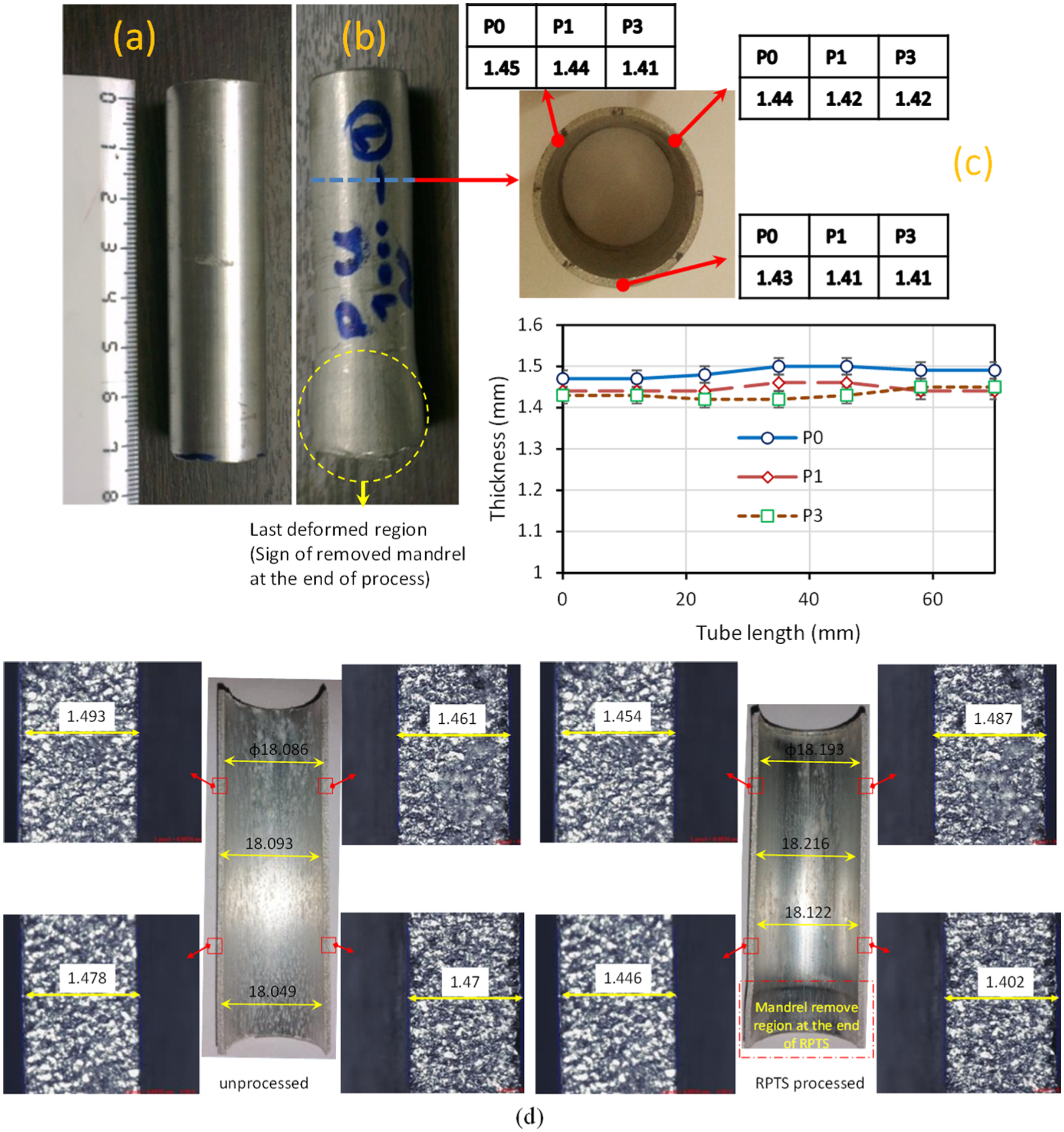
(a) Initial tube, (b) RPTS-processed workpiece at the end of the first pass, (c) thickness distribution along the peripheral and longitudinal direction of unprocessed and RPTS-processed tubes and (d) optical measurement of the diameter and thickness through longitudinal direction of unprocessed and RPTS-processed tubes.
Figure 8 shows the engineering stress–strain curves of the unprocessed and RPTS-processed tubes. Initial tube shows good ductility with relatively little strength while RPTS-processed tubes exhibit less plasticity with higher strength. Fractured tensile samples were arranged next to each other in Figure 8(b). As is seen, the extent of elongation in the unprocessed sample is much higher than the processed samples. Also, larger necking zone was seen in the as-received sample compared to the processed samples. Necking begins at the peak of the stress–strain curve where the plastic deformation is not uniform. After necking, associated with a reduction in the local cross-section with increasing of load, microvoids are formed, enlarged and then merged with each other. This phenomenon contributes to the growth of cracks in a perpendicular direction to the applied force. Before fracture of specimens, the shearing plane is formed with an angle of about 45° relative to the direction of loading. Then, the cracks grow and join causing cup and cone fracture as shown in Figure 8(b). This failure indicates a high level of energy absorption during the fracture process. According to angles and curvature, for processed samples belonging to one pass and three passes samples, has gone to brittle fracture failure mode. Figure 9 summarizes mechanical properties obtained from Figure 8. The yield strength was significantly increased from 80 to 153 MPa after the first RPTS pass. Then, it reaches 172 MPa after third RPTS cycle. In other words, the yield strength increased approximately 2.1 times. The elongation dropped from 33% to 11% after third pass. Also, the ultimate strengths were increased to about 182 MPa from the initial value of about 128 MPa. So, there is a notable increase in the yield strength and ultimate strengths and decrease in the elongation. This can be due to an increase in dislocation density and grain size reduction. 18
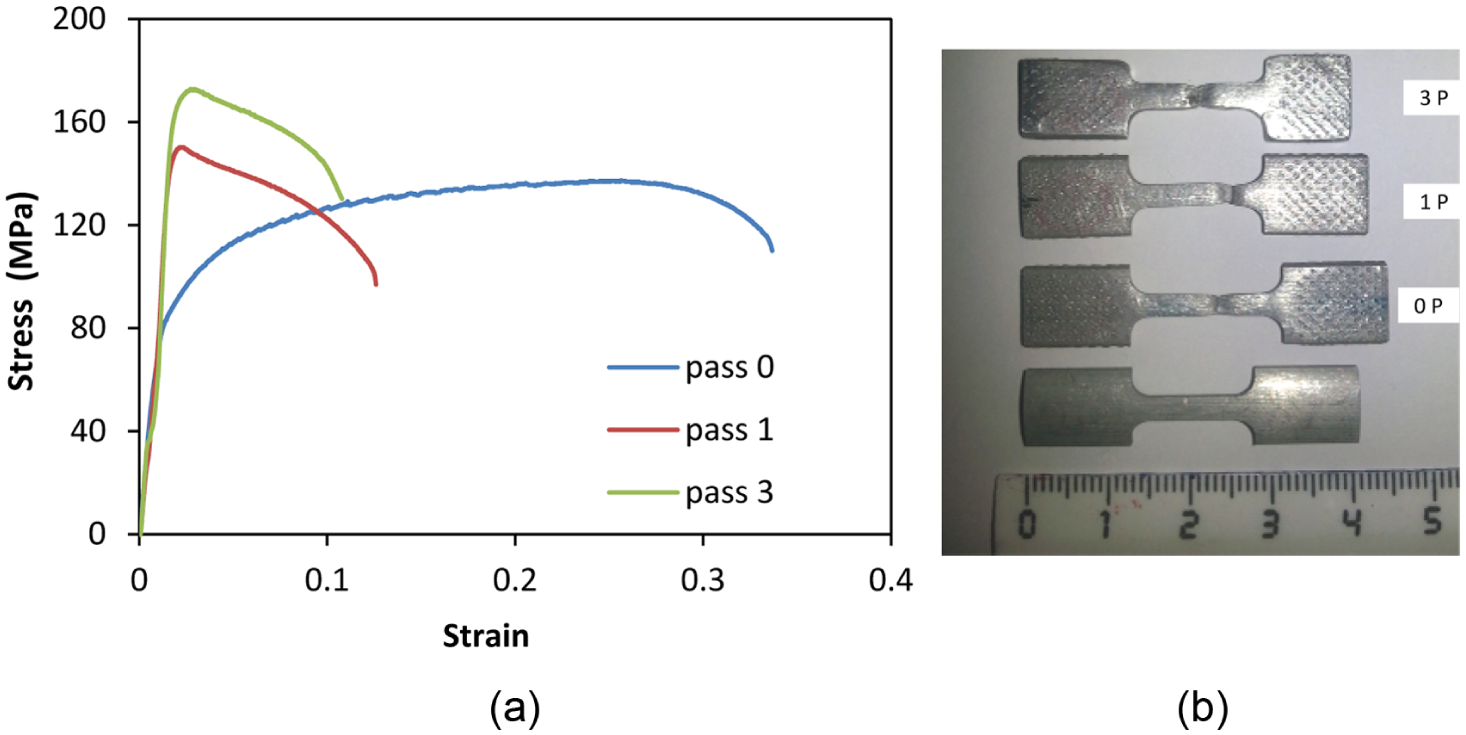
(a) Engineering stress–strain curves of as-received and RPTS-possessed aluminum tubes after different number of passes and (b) fracture tensile specimens before and after the test.
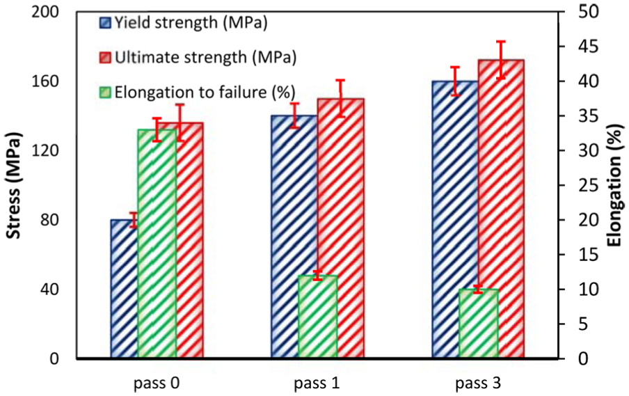
Yield strength, ultimate strength and elongation to failure of as-received and RPTS-possessed aluminum tubes after different number of passes.
Figure 10 shows the morphologies of a fractured surface with two higher magnifications. It can be found that there are distinct differences in the fracture morphologies and dimple sizes for different samples. The morphology of the as-received material is observed as depicted in Figure 10(a) showing a typical dendritic structure with relatively plenty of small and shallow dimples with the size of 3–5 µm. By increasing the numbers of RPTS cycle, the dimples become smaller and deeper, and more constituent parts of the material on the fracture surface and flatten fractured surface can be seen as shown in Figure 10(b) and (c). Formation of microvoid and coalescence includes significant localized plastic deformation that needs good lots of energy, which is the base of a material selection with good fracture toughness.
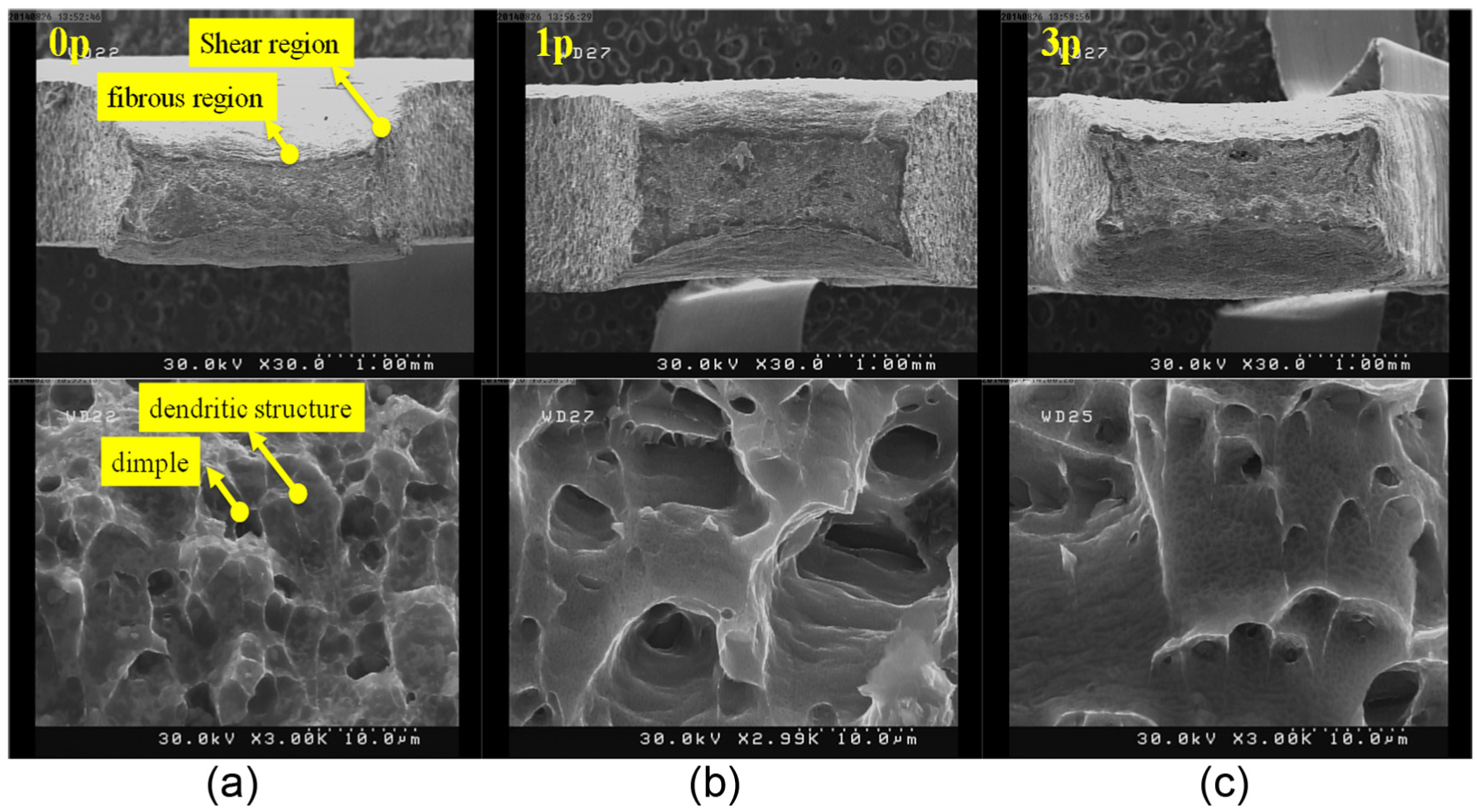
Two magnifications SEM micrograph of the cross-section of fractured (a) before RPTS, (b) one pass and (c) three-pass RPTS-processed tensile samples.
Average microhardness measured across the tube thickness is shown in Figure 11. As can be seen, the third pass processed sample shows the relatively higher hardness of about 53 HV in comparison with the base material with a hardness of about 44 HV. The RPTS process can enhance the material hardness about 21%. This is also visible in other SPD processes such as ECAP, 19 HPT 3 and accumulative back extrusion. 20 Increases in the grain boundaries, the formation of subgrains and grain refinement during the SPD processes can be the main reasons for hardness enhancement during the RPTS cycles.19,21,22
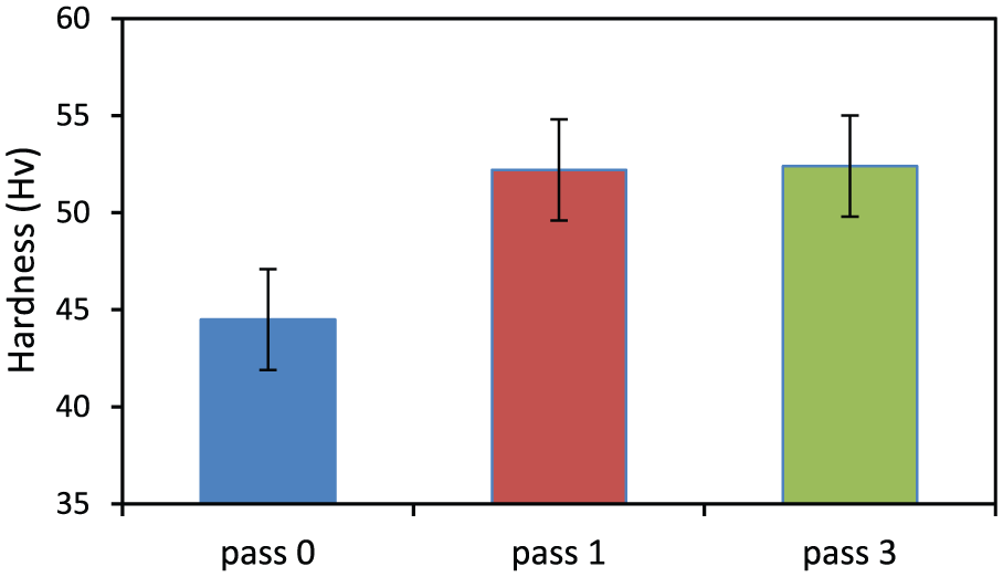
Vickers hardness of different samples.
The effects of friction coefficient between mandrel and tube on equivalent plastic strain contour are shown in Figure 12. As shown in this figure, strain contours and values for two friction coefficient of 0 and 0.05 are almost same. In the friction coefficient of 0.1, the homogeneity of plastic strain is lowered. The effect of friction coefficient on the process load is shown in Figure 13. As shown in this figure, as expected, increase in the friction coefficient leads to increase in the process load.
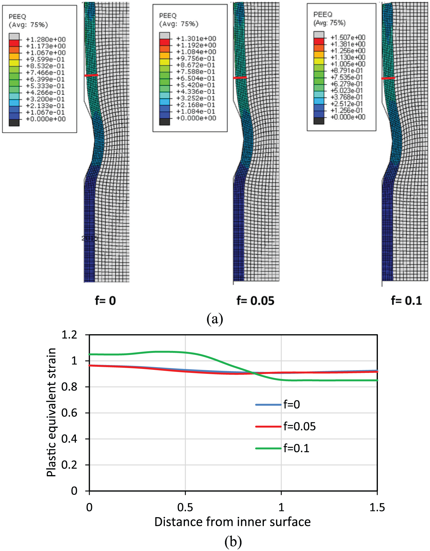
(a) Equivalent plastic strain contour and (b) its variation along the RPTS-processed tube thickness at different friction coefficients of 0, 0.05 and 0.1.
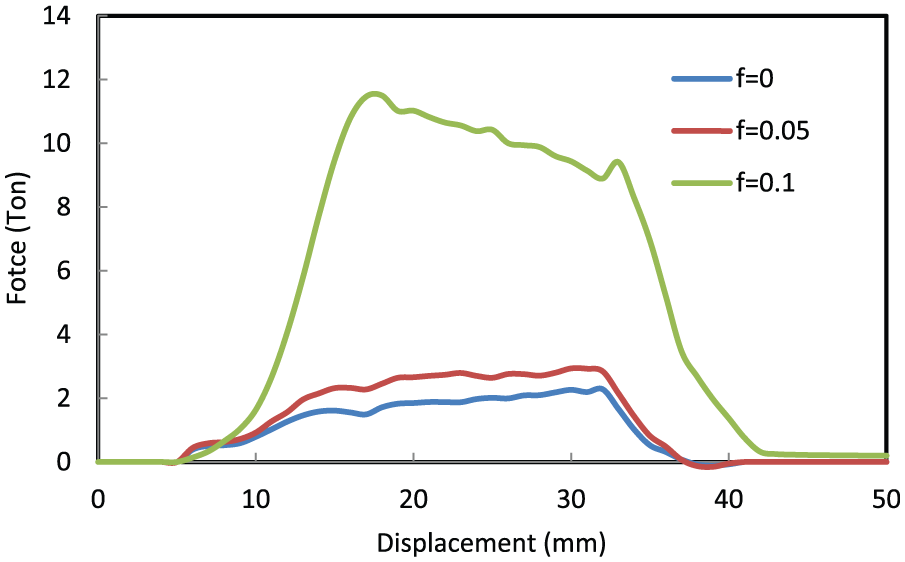
RPTS load displacement curves at different friction coefficients.
Conclusion
The new SPD method entitled RPTS is introduced for the manufacture of relatively long thin-walled UFG tubes. This process is implemented successfully on commercial pure aluminum up to three cycles. The equivalent strain of about 1 was applied through each pass of the process. The yield strength was significantly increased from 80 to 153 MPa after the first RPTS pass. Then, it reaches 172 MPa after third RPTS cycle. In other words, the yield strength increased approximately 2.1 times. The elongation dropped from 33% to 11% after third pass. So, there is a notable increase in the yield and ultimate strengths and decrease in the elongation.
Footnotes
Declaration of conflicting interests
The author(s) declared no potential conflicts of interest with respect to the research, authorship, and/or publication of this article.
Funding
The author(s) disclosed receipt of the following financial support for the research, authorship, and/or publication of this article: This work was financially supported by the Iran National Science Foundation (INSF).